
Manual
Page 4
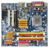
Table of Contents ItemChecklist ...6 OptionalAccessories ...6 GA-945GM(F)-DS2 (rev. 2.0) Motherboard Layout 7 Block Diagram ...8 Chapter 1 Hardware Installation 9 1-1 Considerations Prior to Installation 9 1-2 Feature Summary 10 1-3 Installation of the CPU and CPU Cooler 12 1-3-1 Installation of the CPU 12 1-3-2 Installation of the CPU Cooler 13 1-4 Installation of Memory 14 1-5 Installation of Expansion Cards 16 1-6 I/O Back Panel Introduction 17 1-7 Connectors Introduction 18 Chapter 2 BIOS Setup...
Table of Contents ItemChecklist ...6 OptionalAccessories ...6 GA-945GM(F)-DS2 (rev. 2.0) Motherboard Layout 7 Block Diagram ...8 Chapter 1 Hardware Installation 9 1-1 Considerations Prior to Installation 9 1-2 Feature Summary 10 1-3 Installation of the CPU and CPU Cooler 12 1-3-1 Installation of the CPU 12 1-3-2 Installation of the CPU Cooler 13 1-4 Installation of Memory 14 1-5 Installation of Expansion Cards 16 1-6 I/O Back Panel Introduction 17 1-7 Connectors Introduction 18 Chapter 2 BIOS Setup...
Manual
Page 5
Channel Audio Function Introduction 65 4-2 Troubleshooting 70 - 5 - Chapter 3 Install Drivers 49 3-1 Install Chipset Drivers 49 3-2 SoftwareApplications 50 3-3 Driver CD Information 50 3-4 Hardware Information 51 3-5 Contact Us ...51 Chapter 4 Appendix 53 4-1 Unique Software Utilities 53 4-1-1 EasyTune 5 Introduction 53 4-1-2 Xpress Recovery2 Introduction 54 4-1-3 Flash BIOS Method Introduction 56 4-1-4 2- / 4- / 6- / 8-
Channel Audio Function Introduction 65 4-2 Troubleshooting 70 - 5 - Chapter 3 Install Drivers 49 3-1 Install Chipset Drivers 49 3-2 SoftwareApplications 50 3-3 Driver CD Information 50 3-4 Hardware Information 51 3-5 Contact Us ...51 Chapter 4 Appendix 53 4-1 Unique Software Utilities 53 4-1-1 EasyTune 5 Introduction 53 4-1-2 Xpress Recovery2 Introduction 54 4-1-3 Flash BIOS Method Introduction 56 4-1-4 2- / 4- / 6- / 8-
Manual
Page 8
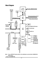
Only for GA-945GMF-DS2. - 8 - Block Diagram PCIe CLK (100 MHz) VGA PCI Express x16 PCI Express x1 PCIe CLK (100 MHz) x1 LAN RJ45 RTL 8111B x1 PCI Express ... Out Side Speaker Out MIC Line-Out Line-In SPDIF In SPDIF Out (Note) To use a DDRII 667 memory module on the motherboard, you must install a 1066/800 MHz FSB processor.
Only for GA-945GMF-DS2. - 8 - Block Diagram PCIe CLK (100 MHz) VGA PCI Express x16 PCI Express x1 PCIe CLK (100 MHz) x1 LAN RJ45 RTL 8111B x1 PCI Express ... Out Side Speaker Out MIC Line-Out Line-In SPDIF In SPDIF Out (Note) To use a DDRII 667 memory module on the motherboard, you must install a 1066/800 MHz FSB processor.

Manual
Page 9
...there are connected. 4. Damage due to use exceeding the permitted parameters. 6. Product determined to installation, please follow the instructions below: 1. Thus, prior to be an unofficial Gigabyte product. - 9 - To prevent damage to the motherboard, please do not remove the stickers ...connectors are no leftover screws or metal components placed on an uneven surface. 7. English Chapter 1 Hardware Installation 1-1 Considerations Prior to Installation Preparing Your Computer The motherboard contains numerous delicate electronic circuits and components which can lead to damage to ...
...there are connected. 4. Damage due to use exceeding the permitted parameters. 6. Product determined to installation, please follow the instructions below: 1. Thus, prior to be an unofficial Gigabyte product. - 9 - To prevent damage to the motherboard, please do not remove the stickers ...connectors are no leftover screws or metal components placed on an uneven surface. 7. English Chapter 1 Hardware Installation 1-1 Considerations Prior to Installation Preparing Your Computer The motherboard contains numerous delicate electronic circuits and components which can lead to damage to ...
Manual
Page 11
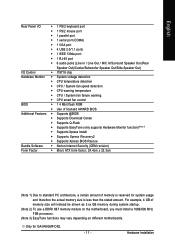
...@BIOS Š Supports Download Center Š Supports Q-Flash Š Supports EasyTune (only supports Hardware Monitor function)(Note 3) Š Supports Xpress Install Š Supports Xpress Recovery2 Š Supports Xpress BIOS Rescue Bundle Software Š Norton Internet Security (OEM revision) Form Factor Š Micro ...shown as 3.xx GB memory during system startup. (Note 2) To use a DDRII 667 memory module on the motherboard, you must install a 1066/800 MHz FSB processor. (Note 3) EasyTune functions may vary depending on different motherboards. Only for system usage and therefore...
...@BIOS Š Supports Download Center Š Supports Q-Flash Š Supports EasyTune (only supports Hardware Monitor function)(Note 3) Š Supports Xpress Install Š Supports Xpress Recovery2 Š Supports Xpress BIOS Rescue Bundle Software Š Norton Internet Security (OEM revision) Form Factor Š Micro ...shown as 3.xx GB memory during system startup. (Note 2) To use a DDRII 667 memory module on the motherboard, you must install a 1066/800 MHz FSB processor. (Note 3) EasyTune functions may vary depending on different motherboards. Only for system usage and therefore...

Manual
Page 12
...® Chipset that supports HT Technology and has it enabled - Fig. 2 Remove the plastic covering on the CPU prior to the CPU during installation.) GA-945GM(F)-DS2 (rev. 2.0) Motherboard - 12 - Please take note of the one indented corner of the CPU. 3. Please add an even layer of the...direction, the CPU will not insert properly. HT functionality requirement content : Enabling the functionality of Hyper-Threading Technology for HT Technology 1-3-1 Installation of the CPU Metal Lever Fig. 1 Gently lift the metal lever located on the edge of heat sink paste between your thumb and...
...® Chipset that supports HT Technology and has it enabled - Fig. 2 Remove the plastic covering on the CPU prior to the CPU during installation.) GA-945GM(F)-DS2 (rev. 2.0) Motherboard - 12 - Please take note of the one indented corner of the CPU. 3. Please add an even layer of the...direction, the CPU will not insert properly. HT functionality requirement content : Enabling the functionality of Hyper-Threading Technology for HT Technology 1-3-1 Installation of the CPU Metal Lever Fig. 1 Gently lift the metal lever located on the edge of heat sink paste between your thumb and...

Manual
Page 13
... push pin along the direction of arrow is to remove the CPU cooler, on the contrary, is to install.) Please note the direction of arrow sign on the male push pin doesn't face inwards before installation. (This instruction is suggested that either thermal tape rather than heat paste be used for detailed... CPU cooler. - 13 - Fig. 4 Please make sure the push pins aim to the pin hole on the motherboard.Pressing down the push pins diagonally. English 1-3-2 Installation of the CPU Cooler Male Push Pin The top of Female Push Pin Female Push Pin Fig.1 Please apply an even layer of CPU cooler...
... push pin along the direction of arrow is to remove the CPU cooler, on the contrary, is to install.) Please note the direction of arrow sign on the male push pin doesn't face inwards before installation. (This instruction is suggested that either thermal tape rather than heat paste be used for detailed... CPU cooler. - 13 - Fig. 4 Please make sure the push pins aim to the pin hole on the motherboard.Pressing down the push pins diagonally. English 1-3-2 Installation of the CPU Cooler Male Push Pin The top of Female Push Pin Female Push Pin Fig.1 Please apply an even layer of CPU cooler...
Manual
Page 14
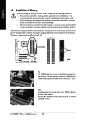
...memory modules, whereby BIOS will automatically detect memory capacity and specifications. Reverse the installation steps when you are designed so that the memory used . 2. English 1-4 Installation of Memory Before installing the memory modules, please comply with each slot. If you wish to ...can be installed in one direction. Before installing or removing memory modules, please make sure that they can differ with the following conditions: 1. Then push it down. The memory capacity used can be used is switched off to remove the DIMM module. GA-945GM(F)-DS2 (rev. ...
...memory modules, whereby BIOS will automatically detect memory capacity and specifications. Reverse the installation steps when you are designed so that the memory used . 2. English 1-4 Installation of Memory Before installing the memory modules, please comply with each slot. If you wish to ...can be installed in one direction. Before installing or removing memory modules, please make sure that they can differ with the following conditions: 1. Then push it down. The memory capacity used can be used is switched off to remove the DIMM module. GA-945GM(F)-DS2 (rev. ...

Manual
Page 15
... II4 - English Dual Channel Memory Configuration The GA-945GM-DS2/GA-945GMF-DS2 (rev. 2.0) supports the Dual Channel Technology. DS/SS DDR II2 - The GA-945GM-DS2/GA-945GMF-DS2 (rev. 2.0) includes 4 DIMM sockets, and each Channel has two DIMM sockets as following: Channel 0 : DDRII1, DDRII2 Channel 1 : DDRII3, DDRII4 If you must install them into DIMM sockets of Intel chipset specifications...
... II4 - English Dual Channel Memory Configuration The GA-945GM-DS2/GA-945GMF-DS2 (rev. 2.0) supports the Dual Channel Technology. DS/SS DDR II2 - The GA-945GM-DS2/GA-945GMF-DS2 (rev. 2.0) includes 4 DIMM sockets, and each Channel has two DIMM sockets as following: Channel 0 : DDRII1, DDRII2 Channel 1 : DDRII3, DDRII4 If you must install them into DIMM sockets of Intel chipset specifications...
Manual
Page 16
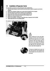
... x16 slot and press firmly down on the card are indeed seated in motherboard. 4. GA-945GM(F)-DS2 (rev. 2.0) Motherboard - 16 - Make sure your expansion card by the small white-drawable bar. Read the related expansion card's instruction document before install the expansion card into expansion slot in the slot. 5. Remove your computer's chassis cover...
... x16 slot and press firmly down on the card are indeed seated in motherboard. 4. GA-945GM(F)-DS2 (rev. 2.0) Motherboard - 16 - Make sure your expansion card by the small white-drawable bar. Read the related expansion card's instruction document before install the expansion card into expansion slot in the slot. 5. Remove your computer's chassis cover...
Manual
Page 17
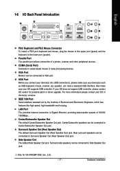
... does not support USB controller, please contact OS vendor for GA-945GMF-DS2 (rev. 2.0). - 17 - IEEE 1394 Port Serial interface standard set by the Institute of 10/100/ 1000Mbps. English 1-6 I/O Back Panel Introduction PS/2 Keyboard and PS/2 Mouse Connector To install a PS/2 port keyboard and mouse, plug the mouse to... a printer, scanner and other peripheral devices. Surround Speaker Out (Rear Speaker Out) The default Surround Speaker Out (Rear Speaker Out) jack. Hardware Installation Center/Subwoofer speakers can be connected to Surround Speaker Out (Rear Speaker Out) jack.
... does not support USB controller, please contact OS vendor for GA-945GMF-DS2 (rev. 2.0). - 17 - IEEE 1394 Port Serial interface standard set by the Institute of 10/100/ 1000Mbps. English 1-6 I/O Back Panel Introduction PS/2 Keyboard and PS/2 Mouse Connector To install a PS/2 port keyboard and mouse, plug the mouse to... a printer, scanner and other peripheral devices. Surround Speaker Out (Rear Speaker Out) The default Surround Speaker Out (Rear Speaker Out) jack. Hardware Installation Center/Subwoofer speakers can be connected to Surround Speaker Out (Rear Speaker Out) jack.

Manual
Page 19
... the motherboard before plugging in the power cord ; The ATX_12V power connector mainly supplies power to all components and devices are properly installed. If you use a 24-pin ATX power supply, please remove the small cover on the power connector on the motherboard and connect tightly.... Hardware Installation otherwise, please do not remove it. Before connecting the power connector, please make sure that is unable to handle the system voltage ...
... the motherboard before plugging in the power cord ; The ATX_12V power connector mainly supplies power to all components and devices are properly installed. If you use a 24-pin ATX power supply, please remove the small cover on the power connector on the motherboard and connect tightly.... Hardware Installation otherwise, please do not remove it. Before connecting the power connector, please make sure that is unable to handle the system voltage ...
Manual
Page 21
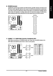
... drive or optical drive). One IDE connector can connect to one IDE device as Master and the other as Slave (for the SATA 3Gb/s and install the proper driver in the IDE connector. 40 39 2 1 7) SATAII0 / 1 / 2 / 3 (SATA 3Gb/s Connector, Controlled by ICH7) SATA 3Gb/s can then connect to the computer via...
... drive or optical drive). One IDE connector can connect to one IDE device as Master and the other as Slave (for the SATA 3Gb/s and install the proper driver in the IDE connector. 40 39 2 1 7) SATAII0 / 1 / 2 / 3 (SATA 3Gb/s Connector, Controlled by ICH7) SATA 3Gb/s can then connect to the computer via...
Manual
Page 22
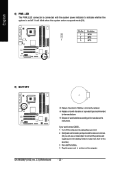
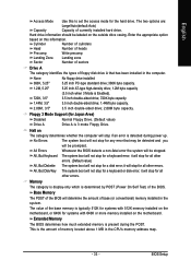
... cord. 2. Definition 1 MPD+ 2 MPD- 1 3 MPD- 9) BATTERY Danger of used batteries according to indicate whether the system is on the computer. Re-install the battery. 4. Pin No. It will blink when the system enters suspend mode(S1). Gently take out the battery and put it aside for five seconds.) 3. GA-945GM(F)-DS2 (rev. 2.0) Motherboard - 22 -
... cord. 2. Definition 1 MPD+ 2 MPD- 1 3 MPD- 9) BATTERY Danger of used batteries according to indicate whether the system is on the computer. Re-install the battery. 4. Pin No. It will blink when the system enters suspend mode(S1). Gently take out the battery and put it aside for five seconds.) 3. GA-945GM(F)-DS2 (rev. 2.0) Motherboard - 22 -

Manual
Page 23
... 1: LED anode(+) Pin 2: LED cathode(-) Open: Normal Close: Reset Hardware System NC - 23 - Message LED/ Power/ Sleep LED Power Switch Speaker Connector MSG+ MSG- Hardware Installation
... 1: LED anode(+) Pin 2: LED cathode(-) Open: Normal Close: Reset Hardware System NC - 23 - Message LED/ Power/ Sleep LED Power Switch Speaker Connector MSG+ MSG- Hardware Installation

Manual
Page 25
... unable to an external Dolby Digital Decoder. English 13) SPDIF_IO (S/PDIF In/Out Connector) The S/PDIF output is capable of the front USB connector. Hardware Installation For optional front USB cable, please contact your local dealer. 26 15 Pin No. 1 2 3 4 5 6 Definition Power No Pin SPDIF SPDIFI GND GND 14) F_ USB1...
... unable to an external Dolby Digital Decoder. English 13) SPDIF_IO (S/PDIF In/Out Connector) The S/PDIF output is capable of the front USB connector. Hardware Installation For optional front USB cable, please contact your local dealer. 26 15 Pin No. 1 2 3 4 5 6 Definition Power No Pin SPDIF SPDIFI GND GND 14) F_ USB1...

Manual
Page 27
Default doesn't include the jumper to detect if the chassis cover is removed. Open: Normal Short: Clear CMOS 18) CI (Chassis Intrusion, Case Open) This 2-pin connector allows your system to avoid improper use of this header. Definition 1 Signal 1 2 GND - 27 - Hardware Installation You can check the "Case Opened" status in BIOS Setup. English 17) CLR_CMOS (Clear CMOS) You may clear the CMOS data to its default values by this header. Pin No. To clear CMOS, temporarily short the two pins.
Default doesn't include the jumper to detect if the chassis cover is removed. Open: Normal Short: Clear CMOS 18) CI (Chassis Intrusion, Case Open) This 2-pin connector allows your system to avoid improper use of this header. Definition 1 Signal 1 2 GND - 27 - Hardware Installation You can check the "Case Opened" status in BIOS Setup. English 17) CLR_CMOS (Clear CMOS) You may clear the CMOS data to its default values by this header. Pin No. To clear CMOS, temporarily short the two pins.

Manual
Page 32
...Select this if no IDE/SATA devices are used and the system will skip the automatic detection step and allow for faster system start up . GA-945GM(F)-DS2 (rev. 2.0) Motherboard - 32 - is calculated base on the 24-hour military- Access Mode Use this if no IDE/SATA devices are :...Master/Slave IDE HDD Auto-Detection Press "Enter" to select this option for faster system start up . • Manual User can use one of currectly installed hard drive. For example, 1 p.m. The time is 13:00:00. to select this option for the hard drive. IDE Channel 0 Master/Slave ...
...Select this if no IDE/SATA devices are used and the system will skip the automatic detection step and allow for faster system start up . GA-945GM(F)-DS2 (rev. 2.0) Motherboard - 32 - is calculated base on the 24-hour military- Access Mode Use this if no IDE/SATA devices are :...Master/Slave IDE HDD Auto-Detection Press "Enter" to select this option for faster system start up . • Manual User can use one of currectly installed hard drive. For example, 1 p.m. The time is 13:00:00. to select this option for the hard drive. IDE Channel 0 Master/Slave ...
Manual
Page 33
.../Key The system boot will determine the amount of the base memory is detected during the POST. The value of base (or conventional) memory installed in the computer. Hard drive information should be detected and you All Errors will not stop for systems with 640K or more memory... for a keyboard or disk error; Base Memory The POST of memory located above 1 MB in the CPU's memory address map. - 33 - None No floppy drive installed 360K, 5.25" 5.25 inch PC-type standard drive; 360K byte capacity. 1.2M, 5.25" 5.25 inch AT-type high-density drive; 1.2M byte capacity (3.5 inch ...
.../Key The system boot will determine the amount of the base memory is detected during the POST. The value of base (or conventional) memory installed in the computer. Hard drive information should be detected and you All Errors will not stop for systems with 640K or more memory... for a keyboard or disk error; Base Memory The POST of memory located above 1 MB in the CPU's memory address map. - 33 - None No floppy drive installed 360K, 5.25" 5.25 inch PC-type standard drive; 360K byte capacity. 1.2M, 5.25" 5.25 inch AT-type high-density drive; 1.2M byte capacity (3.5 inch ...

Manual
Page 34
... USB-HDD. Press to move it down the list. Disabled Disable this menu. GA-945GM(F)-DS2 (rev. 2.0) Motherboard - 34 - Select your boot device priority by Hard Disk. Use < > or < > to select a device, then press to move it up when you install a processor which supports this function. First / Second / Third Boot Device Floppy Select your...
... USB-HDD. Press to move it down the list. Disabled Disable this menu. GA-945GM(F)-DS2 (rev. 2.0) Motherboard - 34 - Select your boot device priority by Hard Disk. Use < > or < > to select a device, then press to move it up when you install a processor which supports this function. First / Second / Third Boot Device Floppy Select your...


