Manual
Page 1
GA-945GM(F)-DS2 (rev. 2.0) Intel® CoreTM 2 Extreme dual-core / CoreTM 2 Duo Intel® Pentium® D / Pentium® 4 / Celeron® D LGA775 Processor Motherboard User's Manual Rev. 2002 12ME-945GMFDR-2002R * The WEEE marking on the product indicates this product must not be disposed of with user's other household waste and must be handed over to a designated collection point for the recycling of waste electrical and electronic equipment!! * The WEEE marking applies only in European Union's member states.
GA-945GM(F)-DS2 (rev. 2.0) Intel® CoreTM 2 Extreme dual-core / CoreTM 2 Duo Intel® Pentium® D / Pentium® 4 / Celeron® D LGA775 Processor Motherboard User's Manual Rev. 2002 12ME-945GMFDR-2002R * The WEEE marking on the product indicates this product must not be disposed of with user's other household waste and must be handed over to a designated collection point for the recycling of waste electrical and electronic equipment!! * The WEEE marking applies only in European Union's member states.

Manual
Page 2
Motherboard GA-945GM-DS2/GA-945GMF-DS2 (rev. 2.0) Nov. 10, 2006 Motherboard GA-945GM-DS2/ GA-945GMF-DS2 (rev. 2.0) Nov. 10, 2006
Motherboard GA-945GM-DS2/GA-945GMF-DS2 (rev. 2.0) Nov. 10, 2006 Motherboard GA-945GM-DS2/ GA-945GMF-DS2 (rev. 2.0) Nov. 10, 2006

Manual
Page 4
Table of Contents ItemChecklist ...6 OptionalAccessories ...6 GA-945GM(F)-DS2 (rev. 2.0) Motherboard Layout 7 Block Diagram ...8 Chapter 1 Hardware Installation 9 1-1 Considerations Prior to Installation 9 1-2 Feature Summary 10 1-3 Installation of the...1-5 Installation of Expansion Cards 16 1-6 I/O Back Panel Introduction 17 1-7 Connectors Introduction 18 Chapter 2 BIOS Setup 29 The Main Menu (For example: GA-945GMF-DS2 BIOS Ver. : F1a 30 2-1 Standard CMOS Features 32 2-2 Advanced BIOS Features 34 2-3 IntegratedPeripherals 36 2-4 Power Management Setup 40 2-5 PnP/PCI Configurations...
Table of Contents ItemChecklist ...6 OptionalAccessories ...6 GA-945GM(F)-DS2 (rev. 2.0) Motherboard Layout 7 Block Diagram ...8 Chapter 1 Hardware Installation 9 1-1 Considerations Prior to Installation 9 1-2 Feature Summary 10 1-3 Installation of the...1-5 Installation of Expansion Cards 16 1-6 I/O Back Panel Introduction 17 1-7 Connectors Introduction 18 Chapter 2 BIOS Setup 29 The Main Menu (For example: GA-945GMF-DS2 BIOS Ver. : F1a 30 2-1 Standard CMOS Features 32 2-2 Advanced BIOS Features 34 2-3 IntegratedPeripherals 36 2-4 Power Management Setup 40 2-5 PnP/PCI Configurations...

Manual
Page 7
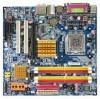
GA-945GM(F)-DS2 (rev. 2.0) Motherboard Layout KB_MS ATX_12V LGA775 CPU_FAN GA-945GM-DS2/GA-945GMF-DS2 IT8718 VGA COMA LPT USB 1394 USB LAN F_AUDIO BATTERY CLR_CMOS AUDIO SYS_FAN PCIE_16 RTL8111B PCI1 PCI2 CD_IN PCIE_1 CODEC SPDIF_IO FDD Intel® 945G DDRII1 DDRII2 BIOS TSB43AB23 Intel® ICH7 COMB F1_1394 F2_1394 DDRII3 DDRII4 SATAII0 SATAII2 IDE ATX CI F_PANEL SATAII1 SATAII3 REV: 2.0 F_USB1 F_USB2 PWR_LED Only for GA-945GMF-DS2. - 7 -
GA-945GM(F)-DS2 (rev. 2.0) Motherboard Layout KB_MS ATX_12V LGA775 CPU_FAN GA-945GM-DS2/GA-945GMF-DS2 IT8718 VGA COMA LPT USB 1394 USB LAN F_AUDIO BATTERY CLR_CMOS AUDIO SYS_FAN PCIE_16 RTL8111B PCI1 PCI2 CD_IN PCIE_1 CODEC SPDIF_IO FDD Intel® 945G DDRII1 DDRII2 BIOS TSB43AB23 Intel® ICH7 COMB F1_1394 F2_1394 DDRII3 DDRII4 SATAII0 SATAII2 IDE ATX CI F_PANEL SATAII1 SATAII3 REV: 2.0 F_USB1 F_USB2 PWR_LED Only for GA-945GMF-DS2. - 7 -

Manual
Page 10
GA-945GM(F)-DS2 (rev. 2.0) Motherboard - 10 - English 1-2 Feature Summary CPU Š LGA775 for Intel® CoreTM 2 Extreme dual-core / CoreTM 2 Duo / Pentium® D / Pentium® 4 / Celeron® D Š L2 ... 4 ports by cables Š 2 IEEE 1394a connectors for additional 2 ports by cables Š 1 COMB connector Š 1 Chassis Intrusion connector Š 1 power LED connector Only for GA-945GMF-DS2.
GA-945GM(F)-DS2 (rev. 2.0) Motherboard - 10 - English 1-2 Feature Summary CPU Š LGA775 for Intel® CoreTM 2 Extreme dual-core / CoreTM 2 Duo / Pentium® D / Pentium® 4 / Celeron® D Š L2 ... 4 ports by cables Š 2 IEEE 1394a connectors for additional 2 ports by cables Š 1 COMB connector Š 1 Chassis Intrusion connector Š 1 power LED connector Only for GA-945GMF-DS2.

Manual
Page 12
...: An Intel® Pentium 4 Processor with HT Technology - Fig. 3 Notice the small gold colored triangle located on the CPU socket to the CPU during installation.) GA-945GM(F)-DS2 (rev. 2.0) Motherboard - 12 -
...: An Intel® Pentium 4 Processor with HT Technology - Fig. 3 Notice the small gold colored triangle located on the CPU socket to the CPU during installation.) GA-945GM(F)-DS2 (rev. 2.0) Motherboard - 12 -
Manual
Page 14
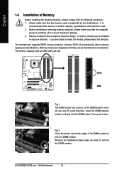
.... Please make sure that they can be used can be installed in one direction. English 1-4 Installation of the DIMM sockets to lock the DIMM module. GA-945GM(F)-DS2 (rev. 2.0) Motherboard - 14 -
.... Please make sure that they can be used can be installed in one direction. English 1-4 Installation of the DIMM sockets to lock the DIMM module. GA-945GM(F)-DS2 (rev. 2.0) Motherboard - 14 -

Manual
Page 15
... modules 4 memory modules DDR II1 DS/SS - DS/SS DS/SS DDR II3 DS/SS - English Dual Channel Memory Configuration The GA-945GM-DS2/GA-945GMF-DS2 (rev. 2.0) supports the Dual Channel Technology. The GA-945GM-DS2/GA-945GMF-DS2 (rev. 2.0) includes 4 DIMM sockets, and each Channel has two DIMM sockets as following explanations due to operate the Dual Channel Technology, please...
... modules 4 memory modules DDR II1 DS/SS - DS/SS DS/SS DDR II3 DS/SS - English Dual Channel Memory Configuration The GA-945GM-DS2/GA-945GMF-DS2 (rev. 2.0) supports the Dual Channel Technology. The GA-945GM-DS2/GA-945GMF-DS2 (rev. 2.0) includes 4 DIMM sockets, and each Channel has two DIMM sockets as following explanations due to operate the Dual Channel Technology, please...
Manual
Page 16
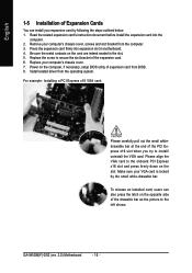
... VGA card. For example: Installing a PCI Express x16 VGA card: Please carefully pull out the small whitedrawable bar at the end of the expansion card. 6. GA-945GM(F)-DS2 (rev. 2.0) Motherboard - 16 - Remove your VGA card is locked by following the steps outlined below: 1. Power on the computer, if necessary, setup BIOS utility of expansion...
... VGA card. For example: Installing a PCI Express x16 VGA card: Please carefully pull out the small whitedrawable bar at the end of the expansion card. 6. GA-945GM(F)-DS2 (rev. 2.0) Motherboard - 16 - Remove your VGA card is locked by following the steps outlined below: 1. Power on the computer, if necessary, setup BIOS utility of expansion...
Manual
Page 17
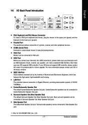
... Monitor can be connected to Center/Subwoofer Speaker Out jack. Also make sure your OS does not support USB controller, please contact OS vendor for GA-945GMF-DS2 (rev. 2.0). - 17 - Center/Subwoofer speakers can be connected to VGA port.
... Monitor can be connected to Center/Subwoofer Speaker Out jack. Also make sure your OS does not support USB controller, please contact OS vendor for GA-945GMF-DS2 (rev. 2.0). - 17 - Center/Subwoofer speakers can be connected to VGA port.

Manual
Page 18
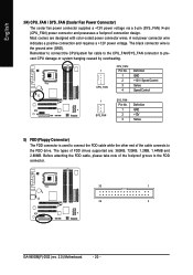
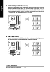
... be connected to Line Out (Front Speaker Out) jack. Only microphones still MUST be connected to the default Mic In jack ( ) . GA-945GM(F)-DS2 (rev. 2.0) Motherboard 10) F_PANEL 11) F_AUDIO 12) CD_IN 13) SPDIF_IO 14) F_USB1 / F_USB2 15) F1_1394 / F2_1394 16) COMB 17) CLR_CMOS... 12 18 13 5 16 15 14 8 10 1) ATX_12V 2) ATX (Power Connector) 3) CPU_FAN 4) SYS_FAN 5) FDD 6) IDE 7) SATAII0 / 1 / 2 / 3 8) PWR_LED 9) BATTERY Only for GA-945GMF-DS2. Please refer to MIC In jack. MIC In The default MIC In jack. In addition to the default speakers settings, the ~ audio jacks can be...
... be connected to Line Out (Front Speaker Out) jack. Only microphones still MUST be connected to the default Mic In jack ( ) . GA-945GM(F)-DS2 (rev. 2.0) Motherboard 10) F_PANEL 11) F_AUDIO 12) CD_IN 13) SPDIF_IO 14) F_USB1 / F_USB2 15) F1_1394 / F2_1394 16) COMB 17) CLR_CMOS... 12 18 13 5 16 15 14 8 10 1) ATX_12V 2) ATX (Power Connector) 3) CPU_FAN 4) SYS_FAN 5) FDD 6) IDE 7) SATAII0 / 1 / 2 / 3 8) PWR_LED 9) BATTERY Only for GA-945GMF-DS2. Please refer to MIC In jack. MIC In The default MIC In jack. In addition to the default speakers settings, the ~ audio jacks can be...
Manual
Page 20
The black connector wire is used to connect the FDD cable while the other end of the foolproof groove in the FDD connector. 33 1 34 2 GA-945GM(F)-DS2 (rev. 2.0) Motherboard - 20 - Before attaching the FDD cable, please take note of the cable connects to prevent CPU damage or system hanging caused by overheating. 1 CPU_FAN ...
The black connector wire is used to connect the FDD cable while the other end of the foolproof groove in the FDD connector. 33 1 34 2 GA-945GM(F)-DS2 (rev. 2.0) Motherboard - 20 - Before attaching the FDD cable, please take note of the cable connects to prevent CPU damage or system hanging caused by overheating. 1 CPU_FAN ...
Manual
Page 22
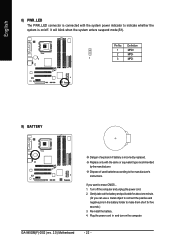
... power cord. 2. Plug the power cord in the battery holder to make them short for about one minute. (Or you want to the manufacturer's instructions. GA-945GM(F)-DS2 (rev. 2.0) Motherboard - 22 - English 8) PWR_LED The PWR_LED connector is connected with the same or equivalent type recommended by the manufacturer. It will blink when the system...
... power cord. 2. Plug the power cord in the battery holder to make them short for about one minute. (Or you want to the manufacturer's instructions. GA-945GM(F)-DS2 (rev. 2.0) Motherboard - 22 - English 8) PWR_LED The PWR_LED connector is connected with the same or equivalent type recommended by the manufacturer. It will blink when the system...
Manual
Page 24
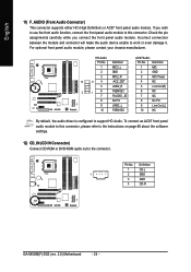
... 9 LINE2_L 9 Line Out (L) 10 FSENSE2 10 NC By default, the audio driver is configured to work or even damage it. Definition 1 CD-L 1 2 GND 3 GND 4 CD-R GA-945GM(F)-DS2 (rev. 2.0) Motherboard - 24 - To connect an AC97 front panel audio module to the connector. Incorrect connection between the module and connector will make the audio device...
... 9 LINE2_L 9 Line Out (L) 10 FSENSE2 10 NC By default, the audio driver is configured to work or even damage it. Definition 1 CD-L 1 2 GND 3 GND 4 CD-R GA-945GM(F)-DS2 (rev. 2.0) Motherboard - 24 - To connect an AC97 front panel audio module to the connector. Incorrect connection between the module and connector will make the audio device...
Manual
Page 26
GA-945GM(F)-DS2 (rev. 2.0) Motherboard - 26 - Check the pin assignments while you connect the IEEE 1394 cable, incorrect connection between the cable and connector will make the device unable ... IEEE 1394 cable, please contact your nearest dealer for optional COMB cable. 9 1 10 2 Pin No. 1 2 3 4 5 6 7 8 9 10 Definition NDCDBNSINB NSOUTB NDTRBGND NDSRBNRTSBNCTSBNRIBNo Pin Only for GA-945GMF-DS2. Be careful with the polarity of Electrical and Electronics Engineers, which has features like high speed, highbandwidth and hot plug. English 15) F1_1394 / F2_1394 (Front...
GA-945GM(F)-DS2 (rev. 2.0) Motherboard - 26 - Check the pin assignments while you connect the IEEE 1394 cable, incorrect connection between the cable and connector will make the device unable ... IEEE 1394 cable, please contact your nearest dealer for optional COMB cable. 9 1 10 2 Pin No. 1 2 3 4 5 6 7 8 9 10 Definition NDCDBNSINB NSOUTB NDTRBGND NDSRBNRTSBNCTSBNRIBNo Pin Only for GA-945GMF-DS2. Be careful with the polarity of Electrical and Electronics Engineers, which has features like high speed, highbandwidth and hot plug. English 15) F1_1394 / F2_1394 (Front...

Manual
Page 28
English GA-945GM(F)-DS2 (rev. 2.0) Motherboard - 28 -
English GA-945GM(F)-DS2 (rev. 2.0) Motherboard - 28 -

Manual
Page 30
... LS120 Hard Disk CDROM ZIP USB-FDD USB-ZIP USB-CDROM USB-HDD LAN KL:Move Enter :Accept ESC:Exit The Main Menu (For example: GA-945GMF-DS2 BIOS Ver. : F1a) Once you want, press "Ctrl+F1" to accept or enter the sub-menu. This action makes the system reset to the..., then press enter to exit this chapter are for reference only and may differ from the exact settings for onboard (or add-on the screen. GA-945GM(F)-DS2 (rev. 2.0) Motherboard - 30 - Use arrow keys to select among the items and press to access advanced options. 2.
... LS120 Hard Disk CDROM ZIP USB-FDD USB-ZIP USB-CDROM USB-HDD LAN KL:Move Enter :Accept ESC:Exit The Main Menu (For example: GA-945GMF-DS2 BIOS Ver. : F1a) Once you want, press "Ctrl+F1" to accept or enter the sub-menu. This action makes the system reset to the..., then press enter to exit this chapter are for reference only and may differ from the exact settings for onboard (or add-on the screen. GA-945GM(F)-DS2 (rev. 2.0) Motherboard - 30 - Use arrow keys to select among the items and press to access advanced options. 2.

Manual
Page 32
... IDE/SATA devices are used and the system will skip the automatic detection step and allow for faster system start up . Through Dec. time clock. GA-945GM(F)-DS2 (rev. 2.0) Motherboard - 32 - For example, 1 p.m. to Dec. 1 to 31 (or maximum allowed in . Jan. English 2-1 Standard CMOS Features Date (mm:dd:yy) Time (hh:mm:ss...
... IDE/SATA devices are used and the system will skip the automatic detection step and allow for faster system start up . Through Dec. time clock. GA-945GM(F)-DS2 (rev. 2.0) Motherboard - 32 - For example, 1 p.m. to Dec. 1 to 31 (or maximum allowed in . Jan. English 2-1 Standard CMOS Features Date (mm:dd:yy) Time (hh:mm:ss...

Manual
Page 34
... it down the list. First / Second / Third Boot Device Floppy Select your boot device priority by Floppy. ZIP Select your boot device priority by ZIP. GA-945GM(F)-DS2 (rev. 2.0) Motherboard - 34 - Use < > or < > to select a device, then press to move it up when you install a processor which supports this function. Select your boot device...
... it down the list. First / Second / Third Boot Device Floppy Select your boot device priority by Floppy. ZIP Select your boot device priority by ZIP. GA-945GM(F)-DS2 (rev. 2.0) Motherboard - 34 - Use < > or < > to select a device, then press to move it up when you install a processor which supports this function. Select your boot device...
Manual
Page 36
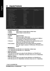
... PCI IDE Enabled Enable onboard 1st channel IDE port. (Default value) Disabled Disable onboard 1st channel IDE port. If PATA IDE were set to ". GA-945GM(F)-DS2 (rev. 2.0) Motherboard - 36 - English 2-3 Integrated Peripherals CMOS Setup Utility-Copyright (C) 1984-2006 Award Software Integrated Peripherals On-Chip Primary PCI IDE On-Chip...On-Chip SATA mode to Enhanced, the motherboard allows up to 4 HDDs on the motherboard; 2 for SATA and the other for GA-945GMF-DS2. PATA devices will auto make by the setting "On-Chip SATA Mode" and "PATA IDE Set to use up to 6 HDDs to ".
... PCI IDE Enabled Enable onboard 1st channel IDE port. (Default value) Disabled Disable onboard 1st channel IDE port. If PATA IDE were set to ". GA-945GM(F)-DS2 (rev. 2.0) Motherboard - 36 - English 2-3 Integrated Peripherals CMOS Setup Utility-Copyright (C) 1984-2006 Award Software Integrated Peripherals On-Chip Primary PCI IDE On-Chip...On-Chip SATA mode to Enhanced, the motherboard allows up to 4 HDDs on the motherboard; 2 for SATA and the other for GA-945GMF-DS2. PATA devices will auto make by the setting "On-Chip SATA Mode" and "PATA IDE Set to use up to 6 HDDs to ".


