
Manual
Page 1
GA-945G-S3 Intel® CoreTM 2 Extreme / CoreTM 2 Duo Intel® Pentium® D / Pentium® 4 LGA775 Processor Motherboard User's Manual Rev. 1001 12ME-945GS3-1001R * The WEEE marking on the product indicates this product must not be disposed of with user's other household waste and must be handed over to a designated collection point for the recycling of waste electrical and electronic equipment!! * The WEEE marking applies only in European Union's member states.
GA-945G-S3 Intel® CoreTM 2 Extreme / CoreTM 2 Duo Intel® Pentium® D / Pentium® 4 LGA775 Processor Motherboard User's Manual Rev. 1001 12ME-945GS3-1001R * The WEEE marking on the product indicates this product must not be disposed of with user's other household waste and must be handed over to a designated collection point for the recycling of waste electrical and electronic equipment!! * The WEEE marking applies only in European Union's member states.

Manual
Page 4
Table of Contents ItemChecklist ...6 OptionalAccessories ...6 GA-945G-S3 Motherboard Layout 7 Block Diagram ...8 Chapter 1 Hardware Installation 9 1-1 Considerations Prior to Installation 9 1-2 Feature Summary 10 1-3 Installation of the CPU and CPU Cooler 12 1-3-1 Installation of the CPU ...
Table of Contents ItemChecklist ...6 OptionalAccessories ...6 GA-945G-S3 Motherboard Layout 7 Block Diagram ...8 Chapter 1 Hardware Installation 9 1-1 Considerations Prior to Installation 9 1-2 Feature Summary 10 1-3 Installation of the CPU and CPU Cooler 12 1-3-1 Installation of the CPU ...

Manual
Page 7
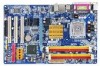
GA-945G-S3 Motherboard Layout KB_MS ATX_12V LGA775 CPU_FAN COMA LPT VGA USB USB LAN ATX GA-945G-S3 DDRII1 DDRII2 DDRII3 DDRII4 AUDIO HDA_SUR RTL8111B F_AUDIO PCIE_3 PCIE_16 Intel® 945G PCIE_1 CODEC PCIE_2 PCI1 IT8718 PCI2 PCI3 CI CD_IN SPDIF_IO SYS_FAN CLR_CMOS BATTERY Intel® ICH7 SATAII0 SATAII2 BIOS SATAII1 SATAII3 IDE1 F_PANEL FDD F_USB1 F_USB2 PWR_LED - 7 -
GA-945G-S3 Motherboard Layout KB_MS ATX_12V LGA775 CPU_FAN COMA LPT VGA USB USB LAN ATX GA-945G-S3 DDRII1 DDRII2 DDRII3 DDRII4 AUDIO HDA_SUR RTL8111B F_AUDIO PCIE_3 PCIE_16 Intel® 945G PCIE_1 CODEC PCIE_2 PCI1 IT8718 PCI2 PCI3 CI CD_IN SPDIF_IO SYS_FAN CLR_CMOS BATTERY Intel® ICH7 SATAII0 SATAII2 BIOS SATAII1 SATAII3 IDE1 F_PANEL FDD F_USB1 F_USB2 PWR_LED - 7 -
Manual
Page 8
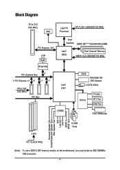
...) VGA LGA775 Processor CPU CLK+/-(266/200/133 MHz) PCI Express x16 LAN RJ45 Host Interface DDRII 667(Note)/533/400 MHz DIMM Intel® 945G Dual Channel Memory GMCH CLK (266/200/133 MHz) RTL8111B PCI Express Bus x1 3 PCI Express x1 x 1 x 1 x 1 Intel® PCIe CLK ICH7 (100 MHz) PCI... Line-Out Line-In SPDIF In SPDIF Out 3 PCI 8 USB Ports PCI CLK(33 MHz) (Note) To use a DDR II 667 memory module on the motherboard, you must install an 800/1066MHz FSB processor. - 8 -
...) VGA LGA775 Processor CPU CLK+/-(266/200/133 MHz) PCI Express x16 LAN RJ45 Host Interface DDRII 667(Note)/533/400 MHz DIMM Intel® 945G Dual Channel Memory GMCH CLK (266/200/133 MHz) RTL8111B PCI Express Bus x1 3 PCI Express x1 x 1 x 1 x 1 Intel® PCIe CLK ICH7 (100 MHz) PCI... Line-Out Line-In SPDIF In SPDIF Out 3 PCI 8 USB Ports PCI CLK(33 MHz) (Note) To use a DDR II 667 memory module on the motherboard, you must install an 800/1066MHz FSB processor. - 8 -
Manual
Page 9
...cables and power connectors are no leftover screws or metal components placed on the motherboard or within a electrostatic shielding container. 5. Please make sure there are connected. 4. Damage due to be an unofficial Gigabyte product. - 9 - Damage due to installation, please do not remove ...the stickers on the computer power during the installation process can become damaged as a result of the motherboard or any hardware, please first carefully read the ...
...cables and power connectors are no leftover screws or metal components placed on the motherboard or within a electrostatic shielding container. 5. Please make sure there are connected. 4. Damage due to be an unofficial Gigabyte product. - 9 - Damage due to installation, please do not remove ...the stickers on the computer power during the installation process can become damaged as a result of the motherboard or any hardware, please first carefully read the ...

Manual
Page 10
... 2 Duo / Pentium® D / Pentium® 4 Š L2 cache varies with CPU Front Side Bus Š Supports 1066/800/533MHz FSB Chipset Š Northbridge: Intel® 945G Express Chipset Š Southbridge: Intel® ICH7 LAN Š Onboard RTL8111B chip (10/100/1000 Mbit) Audio Š Onboard Realtek ALC883 chip Š Supports High... connector Š 1 HDA_SUR connector Š 1 CD In connector Š 2 USB 2.0/1.1 connectors for additional 4 ports by cables Š 1 SPDIF In/Out connector Š 1 power LED connector GA-945G-S3 Motherboard - 10 -
... 2 Duo / Pentium® D / Pentium® 4 Š L2 cache varies with CPU Front Side Bus Š Supports 1066/800/533MHz FSB Chipset Š Northbridge: Intel® 945G Express Chipset Š Southbridge: Intel® ICH7 LAN Š Onboard RTL8111B chip (10/100/1000 Mbit) Audio Š Onboard Realtek ALC883 chip Š Supports High... connector Š 1 HDA_SUR connector Š 1 CD In connector Š 2 USB 2.0/1.1 connectors for additional 4 ports by cables Š 1 SPDIF In/Out connector Š 1 power LED connector GA-945G-S3 Motherboard - 10 -

Manual
Page 11
... 1) To set up an 8 channel audio configuration, you must use a DDR II 667 memory module on the motherboard, you must install an 800/1066MHz FSB processor. (Note 4) EasyTune functions may vary depending on different motherboards. - 11 - English Rear Panel I/O Š 1 PS/2 keyboard port Š 1 PS/2 mouse port Š 1 serial port (COMA) Š...
... 1) To set up an 8 channel audio configuration, you must use a DDR II 667 memory module on the motherboard, you must install an 800/1066MHz FSB processor. (Note 4) EasyTune functions may vary depending on different motherboards. - 11 - English Rear Panel I/O Š 1 PS/2 keyboard port Š 1 PS/2 mouse port Š 1 serial port (COMA) Š...

Manual
Page 12
... the CPU firmly between the CPU and CPU cooler. 4. Chipset: An Intel® Chipset that might cause damage to the CPU during installation.) GA-945G-S3 Motherboard - 12 - BIOS: A BIOS that the motherboard supports the CPU. 2. Fig. 3 Notice the small gold colored triangle located on the CPU socket to your thumb and forefinger, carefully place...
... the CPU firmly between the CPU and CPU cooler. 4. Chipset: An Intel® Chipset that might cause damage to the CPU during installation.) GA-945G-S3 Motherboard - 12 - BIOS: A BIOS that the motherboard supports the CPU. 2. Fig. 3 Notice the small gold colored triangle located on the CPU socket to your thumb and forefinger, carefully place...

Manual
Page 13
Fig. 6 Finally, please attach the power connector of the CPU cooler to install.) Please note the direction of arrow sign on the motherboard.Pressing down the push pins diagonally. Hardware Installation Fig. 2 (Turning the push pin along the direction of arrow is to remove the CPU cooler, ... of the installed CPU. The CPU cooler may adhere to the CPU cooler installation section of the user manual) Fig. 5 Please check the back of motherboard after installing. Fig. 4 Please make sure the push pins aim to the pin hole on the male push pin doesn't face inwards before installation. (...
Fig. 6 Finally, please attach the power connector of the CPU cooler to install.) Please note the direction of arrow sign on the motherboard.Pressing down the push pins diagonally. Hardware Installation Fig. 2 (Turning the push pin along the direction of arrow is to remove the CPU cooler, ... of the installed CPU. The CPU cooler may adhere to the CPU cooler installation section of the user manual) Fig. 5 Please check the back of motherboard after installing. Fig. 4 Please make sure the push pins aim to the pin hole on the male push pin doesn't face inwards before installation. (...
Manual
Page 14
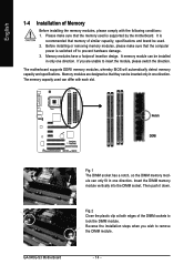
Memory modules have a foolproof insertion design. Notch DDRII GA-945G-S3 Motherboard Fig.1 The DIMM socket has a notch, so the DIMM memory module can be inserted only in only one direction. Fig.2 Close the plastic clip at .... 3. Reverse the installation steps when you are designed so that the memory used . 2. If you wish to insert the module, please switch the direction. The motherboard supports DDRII memory modules, whereby BIOS will automatically detect memory capacity and specifications. The memory capacity used can be used is switched off to lock...
Memory modules have a foolproof insertion design. Notch DDRII GA-945G-S3 Motherboard Fig.1 The DIMM socket has a notch, so the DIMM memory module can be inserted only in only one direction. Fig.2 Close the plastic clip at .... 3. Reverse the installation steps when you are designed so that the memory used . 2. If you wish to insert the module, please switch the direction. The motherboard supports DDRII memory modules, whereby BIOS will automatically detect memory capacity and specifications. The memory capacity used can be used is switched off to lock...

Manual
Page 16
...metal contacts on the slot. Power on the computer, if necessary, setup BIOS utility of the PCI Express x16 slot. Install related driver from BIOS. 8. GA-945G-S3 Motherboard - 16 - When you try uninstall the VGA card, please gently press the latch as the picture to the left shows to the onboard PCI Express... x16 slot and press firmly down on the card are indeed seated in motherboard. 4. Installing a PCI Express x16 expansion card: Please align the VGA card to release the card. Make sure your expansion card by the latch at ...
...metal contacts on the slot. Power on the computer, if necessary, setup BIOS utility of the PCI Express x16 slot. Install related driver from BIOS. 8. GA-945G-S3 Motherboard - 16 - When you try uninstall the VGA card, please gently press the latch as the picture to the left shows to the onboard PCI Express... x16 slot and press firmly down on the card are indeed seated in motherboard. 4. Installing a PCI Express x16 expansion card: Please align the VGA card to release the card. Make sure your expansion card by the latch at ...

Manual
Page 18
English 1-7 Connectors Introduction 1 3 2 12 11 17 10 7 16 6 13 14 4 5 15 9 8 1) ATX_12V 2) ATX (Power Connector) 3) CPU_FAN 4) SYS_FAN 5) FDD 6) IDE1 7) SATAII0/1/2/3 8) F_PANEL 9) PWR_LED 10) BATTERY 11) F_AUDIO 12) HDA_SUR 13) CD_IN 14) SPDIF_IO 15) F_USB1 / F_USB2 16) CI 17) CLR_CMOS GA-945G-S3 Motherboard - 18 -
English 1-7 Connectors Introduction 1 3 2 12 11 17 10 7 16 6 13 14 4 5 15 9 8 1) ATX_12V 2) ATX (Power Connector) 3) CPU_FAN 4) SYS_FAN 5) FDD 6) IDE1 7) SATAII0/1/2/3 8) F_PANEL 9) PWR_LED 10) BATTERY 11) F_AUDIO 12) HDA_SUR 13) CD_IN 14) SPDIF_IO 15) F_USB1 / F_USB2 16) CI 17) CLR_CMOS GA-945G-S3 Motherboard - 18 -

Manual
Page 19
... or a system that is unable to all components and devices are properly installed. Align the power connector with its proper location on the motherboard before plugging in the power cord ; It is not connected, the system will not start . If the ATX_12V power connector is recommended ...that a power supply that all the components on the motherboard. If a power supply is used (300W or greater). English 1/2) ATX_12V/ATX (Power Connector) With the use of the power connector, the ...
... or a system that is unable to all components and devices are properly installed. Align the power connector with its proper location on the motherboard before plugging in the power cord ; It is not connected, the system will not start . If the ATX_12V power connector is recommended ...that a power supply that all the components on the motherboard. If a power supply is used (300W or greater). English 1/2) ATX_12V/ATX (Power Connector) With the use of the power connector, the ...

Manual
Page 20
... cable to the CPU_FAN/SYS_FAN connector to connect the FDD cable while the other end of the foolproof groove in the FDD connector. 33 1 34 2 GA-945G-S3 Motherboard - 20 - The black connector wire is used to prevent CPU damage or system hanging caused by overheating. 1 CPU_FAN CPU_FAN: Pin No.
... cable to the CPU_FAN/SYS_FAN connector to connect the FDD cable while the other end of the foolproof groove in the FDD connector. 33 1 34 2 GA-945G-S3 Motherboard - 20 - The black connector wire is used to prevent CPU damage or system hanging caused by overheating. 1 CPU_FAN CPU_FAN: Pin No.

Manual
Page 22
Pin 3: NC Pin 4: Data(-) Pin 1: LED anode(+) Pin 2: LED cathode(-) Open: Normal Close: Reset Hardware System NC GA-945G-S3 Motherboard - 22 - Message LED/ Power/ Sleep LED Speaker Connector Power Switch MSG+ MSG- English 8) F_PANEL (Front Panel Jumper) Please connect the power LED, PC speaker, reset ...
Pin 3: NC Pin 4: Data(-) Pin 1: LED anode(+) Pin 2: LED cathode(-) Open: Normal Close: Reset Hardware System NC GA-945G-S3 Motherboard - 22 - Message LED/ Power/ Sleep LED Speaker Connector Power Switch MSG+ MSG- English 8) F_PANEL (Front Panel Jumper) Please connect the power LED, PC speaker, reset ...

Manual
Page 24
.... 2 14 1 13 Pin No. 1 2 3 4 5 6 7 8 9 10 11 12 13 14 Definition LEF_P SURR_RR CEN_P SURR_LL CEN_JD SURR_JD GND -SUR_DET GND No Pin GND S_SURR_JD S_SURR_LL S_SURR_RR GA-945G-S3 Motherboard - 24 - Check the pin assignments carefully while you wish to use the front audio function, connect the front panel audio module to this connector.
.... 2 14 1 13 Pin No. 1 2 3 4 5 6 7 8 9 10 11 12 13 14 Definition LEF_P SURR_RR CEN_P SURR_LL CEN_JD SURR_JD GND -SUR_DET GND No Pin GND S_SURR_JD S_SURR_LL S_SURR_RR GA-945G-S3 Motherboard - 24 - Check the pin assignments carefully while you wish to use the front audio function, connect the front panel audio module to this connector.

Manual
Page 26
... Pin NC 16) CI (Chassis Intrusion, Case Open) This 2-pin connector allows your system to work or even damage it. Pin No. Definition 1 1 Signal 2 GND GA-945G-S3 Motherboard - 26 -
... Pin NC 16) CI (Chassis Intrusion, Case Open) This 2-pin connector allows your system to work or even damage it. Pin No. Definition 1 1 Signal 2 GND GA-945G-S3 Motherboard - 26 -
Manual
Page 29
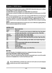
... allows the user to quickly and easily update or backup BIOS without entering the operating system. @BIOS is turned on the motherboard supplies the necessary power to a new BIOS, either GIGABYTE's Q-Flash or @BIOS utility can enter the BIOS setup screen by pressing "Ctrl + F1". English Chapter 2 BIOS Setup BIOS (Basic Input... Menu Item Help Restore the previous CMOS value from CMOS, only for the highlighted item. When the power is displayed at the bottom of the motherboard.
... allows the user to quickly and easily update or backup BIOS without entering the operating system. @BIOS is turned on the motherboard supplies the necessary power to a new BIOS, either GIGABYTE's Q-Flash or @BIOS utility can enter the BIOS setup screen by pressing "Ctrl + F1". English Chapter 2 BIOS Setup BIOS (Basic Input... Menu Item Help Restore the previous CMOS value from CMOS, only for the highlighted item. When the power is displayed at the bottom of the motherboard.

Manual
Page 30
...for reference only and may differ from the exact settings for stability. This action makes the system reset to the default for your motherboard. CMOS Setup Utility-Copyright (C) 1984-2006 Award Software ` Standard CMOS Features ` Advanced BIOS Features ` Integrated Peripherals ` Power ..."Ctrl+F1" to search the advanced option hidden. English : Boot Menu Select boot sequence for 945G-S3 E2 . . . . :BIOS Setup/Q-Flash, : Xpress Recovery2, Boot Menu 07/19/2006-I945-6A79HG06C-00 Boot Menu Use < > or < > to select a device, then press enter to accept . GA-945G-S3 Motherboard - 30 -
...for reference only and may differ from the exact settings for stability. This action makes the system reset to the default for your motherboard. CMOS Setup Utility-Copyright (C) 1984-2006 Award Software ` Standard CMOS Features ` Advanced BIOS Features ` Integrated Peripherals ` Power ..."Ctrl+F1" to search the advanced option hidden. English : Boot Menu Select boot sequence for 945G-S3 E2 . . . . :BIOS Setup/Q-Flash, : Xpress Recovery2, Boot Menu 07/19/2006-I945-6A79HG06C-00 Boot Menu Use < > or < > to select a device, then press enter to accept . GA-945G-S3 Motherboard - 30 -

Manual
Page 32
.../Auto(default:Auto) Capacity Capacity of three methods: • Auto Allows BIOS to select this if no IDE/SATA devices are : Large/Auto(default:Auto) GA-945G-S3 Motherboard - 32 - IDE Channel 2, 3 Master/Slave IDE HDD Auto-Detection Press "Enter" to automatically detect IDE devices during POST. (Default value) • None Select this option...
.../Auto(default:Auto) Capacity Capacity of three methods: • Auto Allows BIOS to select this if no IDE/SATA devices are : Large/Auto(default:Auto) GA-945G-S3 Motherboard - 32 - IDE Channel 2, 3 Master/Slave IDE HDD Auto-Detection Press "Enter" to automatically detect IDE devices during POST. (Default value) • None Select this option...


