User Manual
Page 5
Chapter 3 Drivers Installation 45 3-1 Install Chipset Drivers 45 3-2 SoftwareApplication 46 3-3 Software Information 46 3-4 Hardware Information 47 3-5 Contact Us ...47 Chapter 4 Appendix 49 4-1 Unique Software Utilities 49 4-1-1 EasyTune 5 Introduction 50 4-1-2 Xpress Recovery2 Introduction 51 4-1-3 Flash BIOS Method Introduction 53 4-1-4 Serial ATA BIOS Setting Utility Introduction 62 4-1-5 2 / 4 / 6 Channel Audio Function Introduction 69 4-2 Troubleshooting 74 - 5 -
Chapter 3 Drivers Installation 45 3-1 Install Chipset Drivers 45 3-2 SoftwareApplication 46 3-3 Software Information 46 3-4 Hardware Information 47 3-5 Contact Us ...47 Chapter 4 Appendix 49 4-1 Unique Software Utilities 49 4-1-1 EasyTune 5 Introduction 50 4-1-2 Xpress Recovery2 Introduction 51 4-1-3 Flash BIOS Method Introduction 53 4-1-4 Serial ATA BIOS Setting Utility Introduction 62 4-1-5 2 / 4 / 6 Channel Audio Function Introduction 69 4-2 Troubleshooting 74 - 5 -
User Manual
Page 10
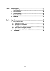
...speed detection Š System voltage detection Š CPU temperature detection GA-8VM800M Motherboard - 10 - English 1-2 Feature Summary CPU Chipset Memory Slots IDE Connections Onboard SATA FDD Connections Peripherals Onboard VGA Onboard LAN Onboard Audio I/O Control Hardware Monitor Š Socket 478 for Intel®...138; 1 VGA port, 1 COMA port, onboard COMB connection Š 8 USB 2.0/1.1 ports (rear x 4, front x 4 via cable) Š 1 front audio connector Š 1 PS/2 keyboard port Š 1 PS/2 mouse port Š Built-in VIA P4M800 Chipset Š Onboard RTL8201 chip (10/100 Mbit) ...
...speed detection Š System voltage detection Š CPU temperature detection GA-8VM800M Motherboard - 10 - English 1-2 Feature Summary CPU Chipset Memory Slots IDE Connections Onboard SATA FDD Connections Peripherals Onboard VGA Onboard LAN Onboard Audio I/O Control Hardware Monitor Š Socket 478 for Intel®...138; 1 VGA port, 1 COMA port, onboard COMB connection Š 8 USB 2.0/1.1 ports (rear x 4, front x 4 via cable) Š 1 front audio connector Š 1 PS/2 keyboard port Š 1 PS/2 mouse port Š Built-in VIA P4M800 Chipset Š Onboard RTL8201 chip (10/100 Mbit) ...
User Manual
Page 22
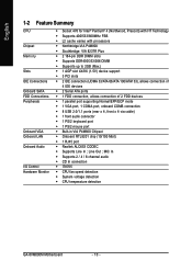
...blink when the system enters suspend mode. Definition 1 1 MPD+ 2 MPD- 3 MPD- 9) F_AUDIO (Front Audio Panel Connector) Please make sure the pin assigment on the cable is on the MB header. If you want ... with the system power indicator to use "Front Audio" connector, you are buying support front audio panel connector, please contact your dealer. Definition 1 MIC 10 9 2 GND 3 2 1 4 MIC_BIAS POWER 5 FrontAudio(R) 6 Rear Audio (R)/ Return R 7 NC 8 No Pin 9 FrontAudio (L) 10 Rear Audio (L)/ Return L GA-8VM800M Motherboard - 22 - Pin No. Pin No....
...blink when the system enters suspend mode. Definition 1 1 MPD+ 2 MPD- 3 MPD- 9) F_AUDIO (Front Audio Panel Connector) Please make sure the pin assigment on the cable is on the MB header. If you want ... with the system power indicator to use "Front Audio" connector, you are buying support front audio panel connector, please contact your dealer. Definition 1 MIC 10 9 2 GND 3 2 1 4 MIC_BIAS POWER 5 FrontAudio(R) 6 Rear Audio (R)/ Return R 7 NC 8 No Pin 9 FrontAudio (L) 10 Rear Audio (L)/ Return L GA-8VM800M Motherboard - 22 - Pin No. Pin No....

User Manual
Page 23
Hardware Installation English 10) CD_IN (CD IN Connector) Connect CD-ROM or DVD-ROM audio out to the connector. 1 Pin No. Definition 1 CD-L 2 GND 3 GND 4 CD-R 11) SUR_CEN Please contact your nearest dealer for optional SUR_CEN cable. 6 5 2 1 Pin No. 1 2 3 4 5 6 Definition SUR OUTL SUR OUTR GND No Pin CENTER_OUT BASS_OUT - 23 -
Hardware Installation English 10) CD_IN (CD IN Connector) Connect CD-ROM or DVD-ROM audio out to the connector. 1 Pin No. Definition 1 CD-L 2 GND 3 GND 4 CD-R 11) SUR_CEN Please contact your nearest dealer for optional SUR_CEN cable. 6 5 2 1 Pin No. 1 2 3 4 5 6 Definition SUR OUTL SUR OUTR GND No Pin CENTER_OUT BASS_OUT - 23 -

User Manual
Page 33
... to 3 when use older OS like NT4. to 3 Enabled Disabled Limit CPUID Maximum value to IDE. (Default value) AC97 Audio Auto Autodetect onboard AC'97 audio function. (Default value) Disabled Disable this function. - 33 - Limit CPUID Max. BIOS Setup Please note that this function.... CMOS Setup Utility-Copyright (C) 1984-2005 Award Software Integrated Peripherals OnChip IDE Channel 0 OnChip IDE Channel 1 OnChip Serial ATA SATA Mode AC97 Audio VIA Onboard LAN USB 1.1 Controller USB 2.0 Controller USB Keyboard Support USB Mouse Support On-Chip LAN Boot ROM Onboard Serial Port 1 Onboard ...
... to 3 when use older OS like NT4. to 3 Enabled Disabled Limit CPUID Maximum value to IDE. (Default value) AC97 Audio Auto Autodetect onboard AC'97 audio function. (Default value) Disabled Disable this function. - 33 - Limit CPUID Max. BIOS Setup Please note that this function.... CMOS Setup Utility-Copyright (C) 1984-2005 Award Software Integrated Peripherals OnChip IDE Channel 0 OnChip IDE Channel 1 OnChip Serial ATA SATA Mode AC97 Audio VIA Onboard LAN USB 1.1 Controller USB 2.0 Controller USB Keyboard Support USB Mouse Support On-Chip LAN Boot ROM Onboard Serial Port 1 Onboard ...
User Manual
Page 69
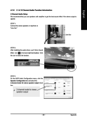
STEP 3: On the AC97 Audio Configuration menu, click the Speaker Configuration tab and select the 2-channel mode for stereo speaker output check box. - 69 - STEP 1: Connect the stereo speakers or earphone to select the function. Appendix Click the icon to "Line Out." English 4-1-5 2 / 4 / 6 Channel Audio Function Introduction 2 Channel Audio Setup We recommend that you 'll find a Sound Effect icon on the lower right hand taskbar. Line Out STEP 2: After installing the audio driver, you use speakers with amplifier to get the best sound effect if the stereo output is applied.
STEP 3: On the AC97 Audio Configuration menu, click the Speaker Configuration tab and select the 2-channel mode for stereo speaker output check box. - 69 - STEP 1: Connect the stereo speakers or earphone to select the function. Appendix Click the icon to "Line Out." English 4-1-5 2 / 4 / 6 Channel Audio Function Introduction 2 Channel Audio Setup We recommend that you 'll find a Sound Effect icon on the lower right hand taskbar. Line Out STEP 2: After installing the audio driver, you use speakers with amplifier to get the best sound effect if the stereo output is applied.
User Manual
Page 70
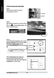
Clear the Only SURROUND-KIT check box and press OK. GA-8VM800M Motherboard - 70 - STEP 3: On the AC97 Audio Configuration menu, click the Speaker Configuration tab and select the 4-channel mode for 4-channel output. Line Out Line In English 4 Channel Analog Audio Output Mode STEP 1: Connect the front channels to "Line Out...," the rear channels to select the function. STEP 2: After installing the audio driver, you'll find a Sound Effect icon on the lower right hand taskbar. Click the icon to "Line In." Please select other ...
Clear the Only SURROUND-KIT check box and press OK. GA-8VM800M Motherboard - 70 - STEP 3: On the AC97 Audio Configuration menu, click the Speaker Configuration tab and select the 4-channel mode for 4-channel output. Line Out Line In English 4 Channel Analog Audio Output Mode STEP 1: Connect the front channels to "Line Out...," the rear channels to select the function. STEP 2: After installing the audio driver, you'll find a Sound Effect icon on the lower right hand taskbar. Click the icon to "Line In." Please select other ...
User Manual
Page 71
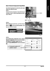
... to "MIC In". Line In STEP 3: On the AC97 Audio Configuration menu, click the Speaker Configuration tab and select the 6-channel mode for 5.1 speaker output check box. Clear the Only SURROUND-KIT check box and ... OK. - 71 - Appendix STEP 1: Connect the front channels to "Line Out",the rear channels to "Line In", and the Center/Subwoofer channels to connect the audio output without any additional module. Click the icon to select the function. MIC In Line Out STEP 2: After installing the...
... to "MIC In". Line In STEP 3: On the AC97 Audio Configuration menu, click the Speaker Configuration tab and select the 6-channel mode for 5.1 speaker output check box. Clear the Only SURROUND-KIT check box and ... OK. - 71 - Appendix STEP 1: Connect the front channels to "Line Out",the rear channels to "Line In", and the Center/Subwoofer channels to connect the audio output without any additional module. Click the icon to select the function. MIC In Line Out STEP 2: After installing the...
User Manual
Page 72
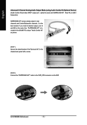
... in the GIGABYTE unique "Audio Combo Kit" as picture. "SURROUND-KIT" is the best solution if you need 6 channel output, Line In and MIC at the same time. STEP 1: Secure the metal bracket of the"Surround Kit" to the SUR_CEN connector on the M/B. GA-8VM800M Motherboard - 72... - STEP 2: Connect the "SURROUND-KIT" cable to the chassis back panel with a screw. English Advanced 6 Channel Analog Audio Output Mode (using Audio Combo Kit,Optional Device): (Audio Combo Kit provides SPDIF output port : optical &...
... in the GIGABYTE unique "Audio Combo Kit" as picture. "SURROUND-KIT" is the best solution if you need 6 channel output, Line In and MIC at the same time. STEP 1: Secure the metal bracket of the"Surround Kit" to the SUR_CEN connector on the M/B. GA-8VM800M Motherboard - 72... - STEP 2: Connect the "SURROUND-KIT" cable to the chassis back panel with a screw. English Advanced 6 Channel Analog Audio Output Mode (using Audio Combo Kit,Optional Device): (Audio Combo Kit provides SPDIF output port : optical &...
User Manual
Page 73
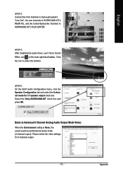
...-KIT's REAR R/L, and the Center/Subwoofer channels to select the function. STEP 4: After installing the audio driver, you'll find a Sound Effect icon on the lower right hand taskbar. Basic & Advanced 6 Channel Analog Audio Output Mode Notes: When the Environment setting is None, the sound would be performed as stereo mode... check box. Select the Only SURROUND-KIT check box and press OK. Click the icon to SURROUND-KIT's SUB CENTER. STEP 5: On the AC97 Audio Configuration menu, click the Speaker Configuration tab and select the 6-channel mode for 6 channels output. - 73 - Appendix
...-KIT's REAR R/L, and the Center/Subwoofer channels to select the function. STEP 4: After installing the audio driver, you'll find a Sound Effect icon on the lower right hand taskbar. Basic & Advanced 6 Channel Analog Audio Output Mode Notes: When the Environment setting is None, the sound would be performed as stereo mode... check box. Select the Only SURROUND-KIT check box and press OK. Click the icon to SURROUND-KIT's SUB CENTER. STEP 5: On the AC97 Audio Configuration menu, click the Speaker Configuration tab and select the 6-channel mode for 6 channels output. - 73 - Appendix


