
User Manual
Page 4
... CPU 12 1-3-2 Installation of the Heatsink 13 1-4 Installation of Memory 14 1-5 Installation of Expansion Cards 15 1-6 I/O Back Panel Introduction 16 1-7 Connectors Introduction 17 Chapter 2 BIOS Setup 27 The Main Menu (For example: BIOS Ver. : F1a 28 2-1 Standard CMOS Features 29 2-2 Advanced BIOS Features 32 2-3 IntegratedPeripherals 33 2-4 Power Management Setup 35 2-5 PnP/PCI Configurations 37 2-6 PC Health Status 38 2-7 Frequency / Voltage Control 39 2-8 Load Fail-Safe Defaults 41 2-9 Load Optimized Defaults 41 2-10 Set Supervisor/User Password 42 2-11 Save & Exit Setup...
... CPU 12 1-3-2 Installation of the Heatsink 13 1-4 Installation of Memory 14 1-5 Installation of Expansion Cards 15 1-6 I/O Back Panel Introduction 16 1-7 Connectors Introduction 17 Chapter 2 BIOS Setup 27 The Main Menu (For example: BIOS Ver. : F1a 28 2-1 Standard CMOS Features 29 2-2 Advanced BIOS Features 32 2-3 IntegratedPeripherals 33 2-4 Power Management Setup 35 2-5 PnP/PCI Configurations 37 2-6 PC Health Status 38 2-7 Frequency / Voltage Control 39 2-8 Load Fail-Safe Defaults 41 2-9 Load Optimized Defaults 41 2-10 Set Supervisor/User Password 42 2-11 Save & Exit Setup...
User Manual
Page 10
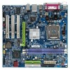
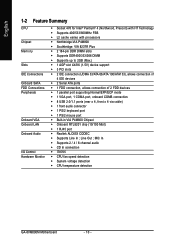
... Š CPU fan speed detection Š System voltage detection Š CPU temperature detection GA-8VM800M Motherboard - 10 - English 1-2 Feature Summary CPU Chipset Memory Slots IDE Connections Onboard SATA FDD Connections Peripherals Onboard VGA Onboard LAN Onboard Audio I/O Control Hardware Monitor Š Socket 478 for Intel® Pentium® 4 (Northwood, Prescott) with HT Technology Š Supports 400/533/800MHz FSB Š L2 cache varies with processors Š Northbridge:VIA P4M800 Š Southbridge: VIA 8237R Plus Š 2 184-pin DDR DIMM slots Š Supports DDR400...
... Š CPU fan speed detection Š System voltage detection Š CPU temperature detection GA-8VM800M Motherboard - 10 - English 1-2 Feature Summary CPU Chipset Memory Slots IDE Connections Onboard SATA FDD Connections Peripherals Onboard VGA Onboard LAN Onboard Audio I/O Control Hardware Monitor Š Socket 478 for Intel® Pentium® 4 (Northwood, Prescott) with HT Technology Š Supports 400/533/800MHz FSB Š L2 cache varies with processors Š Northbridge:VIA P4M800 Š Southbridge: VIA 8237R Plus Š 2 184-pin DDR DIMM slots Š Supports DDR400...
User Manual
Page 20
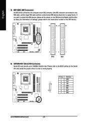
... settings, please refer to the instructions located on one IDE cable, and the single IDE cable can connect to one IDE device as Master and the other as Slave (for the Serial ATA and install the proper driver in order to 150MB/s transfer rate. Definition 1 GND 2 TXP 1 3 TXN 4 GND 5 RXN 6 RXP 7 7 GND GA-8VM800M Motherboard - 20 - Pin No. English 5) IDE1/IDE2 (IDE Connector) An IDE device connects to two IDE devices (hard drive or optical drive). One IDE connector...
... settings, please refer to the instructions located on one IDE cable, and the single IDE cable can connect to one IDE device as Master and the other as Slave (for the Serial ATA and install the proper driver in order to 150MB/s transfer rate. Definition 1 GND 2 TXP 1 3 TXN 4 GND 5 RXN 6 RXP 7 7 GND GA-8VM800M Motherboard - 20 - Pin No. English 5) IDE1/IDE2 (IDE Connector) An IDE device connects to two IDE devices (hard drive or optical drive). One IDE connector...
User Manual
Page 21
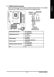
RESRES+ NC HD (IDE Hard Disk Active LED) SPEAK (Speaker Connector) RES (Reset Switch) PW (Power Switch) MSG(Message LED/Power/Sleep LED) NC Reset Switch IDE Hard Disk Active LED Pin 1: LED anode(+) Pin 2: LED cathode(-) Pin 1: Power Pin 2- of your chassis front panel to the F_PANEL connector according to the pin assignments below. Pin 3: NC Pin 4: Data(-) Open: Normal Close: Reset Hardware System Open: Normal Close: Power On/Off Pin 1: LED anode(+) Pin 2: LED cathode(-) NC - 21 - Hardware Installation Message LED/ Power/ Sleep LED Speaker Connector Power Switch MSG+ MSG- PW+ ...
RESRES+ NC HD (IDE Hard Disk Active LED) SPEAK (Speaker Connector) RES (Reset Switch) PW (Power Switch) MSG(Message LED/Power/Sleep LED) NC Reset Switch IDE Hard Disk Active LED Pin 1: LED anode(+) Pin 2: LED cathode(-) Pin 1: Power Pin 2- of your chassis front panel to the F_PANEL connector according to the pin assignments below. Pin 3: NC Pin 4: Data(-) Open: Normal Close: Reset Hardware System Open: Normal Close: Power On/Off Pin 1: LED anode(+) Pin 2: LED cathode(-) NC - 21 - Hardware Installation Message LED/ Power/ Sleep LED Speaker Connector Power Switch MSG+ MSG- PW+ ...
User Manual
Page 28
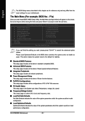
...for your motherboard. GA-8VM800M Motherboard - 28 - Use arrow keys to select among the items and press to search the advanced option hidden. CMOS Setup Utility-Copyright (C) 1984-2005 Award Software ` Standard CMOS Features ` Advanced BIOS Features ` Integrated Peripherals ` Power Management Setup ` PnP/PCI Configurations ` PC Health Status ` Frequency/Voltage Control ESC: Quit F8: Q-Flash Load Fail-Safe Defaults Load Optimized Defaults Set Supervisor Password Set User Password Save & Exit Setup Exit Without Saving KLJI: Select Item F10: Save & Exit Setup Time, Date, Hard Disk Type...
...for your motherboard. GA-8VM800M Motherboard - 28 - Use arrow keys to select among the items and press to search the advanced option hidden. CMOS Setup Utility-Copyright (C) 1984-2005 Award Software ` Standard CMOS Features ` Advanced BIOS Features ` Integrated Peripherals ` Power Management Setup ` PnP/PCI Configurations ` PC Health Status ` Frequency/Voltage Control ESC: Quit F8: Q-Flash Load Fail-Safe Defaults Load Optimized Defaults Set Supervisor Password Set User Password Save & Exit Setup Exit Without Saving KLJI: Select Item F10: Save & Exit Setup Time, Date, Hard Disk Type...

User Manual
Page 29
...: Save F6: Fail-Safe Defaults 1999 to set the access mode for faster system start up. IDE Channel 0/1 Master, Slave IDE HDD Auto-Detection Press "Enter" to select this to 2098 ESC: Exit F1: General Help F7: Optimized Defaults Date The date format is calculated base on the 24-hour military-time clock. IDE Device Setup. You can manually input the correct settings Access Mode Use this option for automatic device detection. It allows...
...: Save F6: Fail-Safe Defaults 1999 to set the access mode for faster system start up. IDE Channel 0/1 Master, Slave IDE HDD Auto-Detection Press "Enter" to select this to 2098 ESC: Exit F1: General Help F7: Optimized Defaults Date The date format is calculated base on the 24-hour military-time clock. IDE Device Setup. You can manually input the correct settings Access Mode Use this option for automatic device detection. It allows...

User Manual
Page 35
Disabled Disable this function. (Default value) 2-4 Power Management Setup CMOS Setup Utility-Copyright (C) 1984-2005 Award Software Power Management Setup ACPI Suspend Type x USB Device Wake-Up From S3 Soft-Off by PWRBTN AC BACK Function Keyboard Power On Mouse Power On PME Event Wake Up Modem Ring Resume Resume by PWRBTN Instant-Off Press power button then Power off . BIOS Setup Press power button 4 sec. USB Device Wake-Up From S3 Disabled Disable USB Device Wake-Up from S3. (Default value) Enabled Enable USB Device Wake-Up from S3. Enter suspend if button is...
Disabled Disable this function. (Default value) 2-4 Power Management Setup CMOS Setup Utility-Copyright (C) 1984-2005 Award Software Power Management Setup ACPI Suspend Type x USB Device Wake-Up From S3 Soft-Off by PWRBTN AC BACK Function Keyboard Power On Mouse Power On PME Event Wake Up Modem Ring Resume Resume by PWRBTN Instant-Off Press power button then Power off . BIOS Setup Press power button 4 sec. USB Device Wake-Up From S3 Disabled Disable USB Device Wake-Up from S3. (Default value) Enabled Enable USB Device Wake-Up from S3. Enter suspend if button is...
User Manual
Page 39
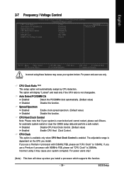
... is not changeable. English 2-7 Frequency / Voltage Control CMOS Setup Utility-Copyright (C) 1984-2005 Award Software Frequency/Voltage Control CPU Clock Ratio (Note) Auto Detect PCI/DIMM Clk Spread Spectrum CPU Host Clock Control x CPU Clock DRAM Clock DIMM OverVoltage Control [21X] [Enabled] [Enabled] [Disabled] 100MHz [By SPD] [Auto] Item Help Menu Level` KLJI: Move Enter: Select F5: Previous Values +/-/PU/PD: Value F10: Save F6: Fail-Safe Defaults ESC: Exit F1: General Help F7: Optimized Defaults Incorrect using it may cause your system...
... is not changeable. English 2-7 Frequency / Voltage Control CMOS Setup Utility-Copyright (C) 1984-2005 Award Software Frequency/Voltage Control CPU Clock Ratio (Note) Auto Detect PCI/DIMM Clk Spread Spectrum CPU Host Clock Control x CPU Clock DRAM Clock DIMM OverVoltage Control [21X] [Enabled] [Enabled] [Disabled] 100MHz [By SPD] [Auto] Item Help Menu Level` KLJI: Move Enter: Select F5: Previous Values +/-/PU/PD: Value F10: Save F6: Fail-Safe Defaults ESC: Exit F1: General Help F7: Optimized Defaults Incorrect using it may cause your system...
User Manual
Page 42
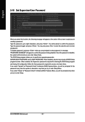
...2-10 Set Supervisor/User Password CMOS Setup Utility-Copyright (C) 1984-2005 Award Software ` Standard CMOS Features ` Advanced BIOS Features ` Integrated Peripherals ` Power Management Setup ` PnP/PCI ConfigurationEsnter Password: ` PC Health Status ` Frequency/Voltage Control Load Fail-Safe Defaults Load Optimized Defaults Set Supervisor Password Set User Password Save & Exit Setup Exit Without Saving ESC: Quit F8: Q-Flash KLJI: Select Item F10: Save & Exit Setup Change/Set/Disable Password When you select this function, the following message will appear at the center of the screen to...
...2-10 Set Supervisor/User Password CMOS Setup Utility-Copyright (C) 1984-2005 Award Software ` Standard CMOS Features ` Advanced BIOS Features ` Integrated Peripherals ` Power Management Setup ` PnP/PCI ConfigurationEsnter Password: ` PC Health Status ` Frequency/Voltage Control Load Fail-Safe Defaults Load Optimized Defaults Set Supervisor Password Set User Password Save & Exit Setup Exit Without Saving ESC: Quit F8: Q-Flash KLJI: Select Item F10: Save & Exit Setup Change/Set/Disable Password When you select this function, the following message will appear at the center of the screen to...
User Manual
Page 49
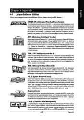
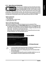
... loading. With GIGABYTE's proprietary S.O.S. Download Center Download Center allows users to quickly download and update their computer system to factory default settings. S.O.S. (System Overclock Saver) System Overclock Saver (S.O.S.) is a unique feature that allows system hardware information such as providing the most up to -date drivers and BIOS. (Do not use C.O.M. Instead, S.O.S. M.I.B.2 (Memory Intelligent Booster 2) Built on the motherboard to reset the system back to the desired level. C.I.A.2 (CPU...
... loading. With GIGABYTE's proprietary S.O.S. Download Center Download Center allows users to quickly download and update their computer system to factory default settings. S.O.S. (System Overclock Saver) System Overclock Saver (S.O.S.) is a unique feature that allows system hardware information such as providing the most up to -date drivers and BIOS. (Do not use C.O.M. Instead, S.O.S. M.I.B.2 (Memory Intelligent Booster 2) Built on the motherboard to reset the system back to the desired level. C.I.A.2 (CPU...
User Manual
Page 51
... installations of the hard disk will appear in your CD-ROM drive. System storage capacity and the reading/writing speed of OS and all required drivers as well as software. - 51 - It is executed from CD/DVD: Xpress Recovery2 1. Press any key to enter Xpress Recovery2. If you can enter Xpress Recovery2 by pressing the F9 key: Steps: After entering BIOS Setup, go to Advanced BIOS Feature and set...
... installations of the hard disk will appear in your CD-ROM drive. System storage capacity and the reading/writing speed of OS and all required drivers as well as software. - 51 - It is executed from CD/DVD: Xpress Recovery2 1. Press any key to enter Xpress Recovery2. If you can enter Xpress Recovery2 by pressing the F9 key: Steps: After entering BIOS Setup, go to Advanced BIOS Feature and set...
User Manual
Page 54
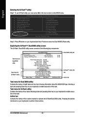
... Set User Password Save & Exit Setup Exit Without Saving F3: Change Language F10: Save & Exit Setup Time, Date, Hard Disk Type... GA-8VM800M Motherboard - 54 - English Entering the Q-FlashTM utility: Step1: To use Q-Flash utility, you must press Del in the boot screen to enable execution of the task. Task menu for Dual BIOS utility Task menu for Q-FlashTM utility Dual BIOS Utility Boot From Main Bios Main ROM Type/Size SST 49LF003A Backup ROM Type/Size SST 49LF003A 512K 512K Wide Range Protection Disable Boot From Main Bios Auto Recovery Enable Halt On Error Disable Copy Main...
... Set User Password Save & Exit Setup Exit Without Saving F3: Change Language F10: Save & Exit Setup Time, Date, Hard Disk Type... GA-8VM800M Motherboard - 54 - English Entering the Q-FlashTM utility: Step1: To use Q-Flash utility, you must press Del in the boot screen to enable execution of the task. Task menu for Dual BIOS utility Task menu for Q-FlashTM utility Dual BIOS Utility Boot From Main Bios Main ROM Type/Size SST 49LF003A Backup ROM Type/Size SST 49LF003A 512K 512K Wide Range Protection Disable Boot From Main Bios Auto Recovery Enable Halt On Error Disable Copy Main...
User Manual
Page 55
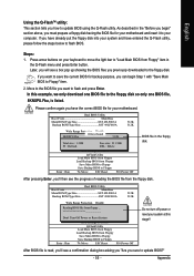
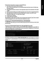
... a floppy disk having the BIOS file for your motherboard and insert it to Floppy Enter : Run :Move ESC:Reset F10:Power Off BIOS file in the Q-Flash menu and press Enter button. Press arrow buttons on your computer. After pressing Enter, you'll then see a box pop up showing the BIOS files you sure to "Load Main BIOS from Floppy Save Main BIOS to Floppy Save Backup BIOS to your keyboard to move the light bar to update BIOS?" - 55 - Dual BIOS Utility Boot From Main Bios Main ROM Type/Size...
... a floppy disk having the BIOS file for your motherboard and insert it to Floppy Enter : Run :Move ESC:Reset F10:Power Off BIOS file in the Q-Flash menu and press Enter button. Press arrow buttons on your computer. After pressing Enter, you'll then see a box pop up showing the BIOS files you sure to "Load Main BIOS from Floppy Save Main BIOS to Floppy Save Backup BIOS to your keyboard to move the light bar to update BIOS?" - 55 - Dual BIOS Utility Boot From Main Bios Main ROM Type/Size...
User Manual
Page 56
... the BIOS version on your boot screen becomes the one you flashed. Load Default Settings Save Settings to CMOS Q-Flash Utility Load Main BIOS from Floppy Load Backup BIOS from Floppy Save Main BIOS to Floppy Save Backup BIOS to Floppy Enter : Run :Move ESC:Reset F10:Power Off You can repeat Step 1 to 4 to update BIOS. Award Modular BIOS v6.00PG, An Energy Star Ally Copyright (C) 1984-2003, Award Software, Inc. The progress of updating BIOS will restart automatically after updating. Dual BIOS Utility Boot From Main Bios Main ROM Type/Size SST 49LF003A Backup ROM Type/Size...
... the BIOS version on your boot screen becomes the one you flashed. Load Default Settings Save Settings to CMOS Q-Flash Utility Load Main BIOS from Floppy Load Backup BIOS from Floppy Save Main BIOS to Floppy Save Backup BIOS to Floppy Enter : Run :Move ESC:Reset F10:Power Off You can repeat Step 1 to 4 to update BIOS. Award Modular BIOS v6.00PG, An Energy Star Ally Copyright (C) 1984-2003, Award Software, Inc. The progress of updating BIOS will restart automatically after updating. Dual BIOS Utility Boot From Main Bios Main ROM Type/Size SST 49LF003A Backup ROM Type/Size...

User Manual
Page 57
... Enter to update BIOS using the Q-FlashTM utility. English 6. CMOS Setup Utility-Copyright (C) 1984-2004 Award Software Standard CMOS Features Select Language Advanced BIOS Features Load Fail-Safe Defaults Integrated Peripherals Load Optimized Defaults Power Management Setup Load Fail-Safe Defaults (YS/eNt )S?uYpervisor Password PnP/PCI Configurations Set User Password PC Health Status Save & Exit Setup MB Intelligent Tweaker(M.I.T.) Exit Without Saving ESC: Quit F8: Dual BIOS/Q-Flash F3: Change Language F10: Save & Exit Setup Time, Date, Hard Disk Type... Appendix...
... Enter to update BIOS using the Q-FlashTM utility. English 6. CMOS Setup Utility-Copyright (C) 1984-2004 Award Software Standard CMOS Features Select Language Advanced BIOS Features Load Fail-Safe Defaults Integrated Peripherals Load Optimized Defaults Power Management Setup Load Fail-Safe Defaults (YS/eNt )S?uYpervisor Password PnP/PCI Configurations Set User Password PC Health Status Save & Exit Setup MB Intelligent Tweaker(M.I.T.) Exit Without Saving ESC: Quit F8: Dual BIOS/Q-Flash F3: Change Language F10: Save & Exit Setup Time, Date, Hard Disk Type... Appendix...
User Manual
Page 60
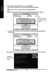
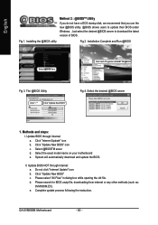
... process following the instruction. GA-8VM800M Motherboard - 60 - Installation Complete and Run @BIOS Select @BIOS item Click Sart/ Programs/ GIGABYTE/@BIOS Fig 3. Click "Update New BIOS" c. The @BIOS Utility Click " " Click "Update New BIOS" Fig 4. Click "Internet Update" icon b. System will automatically download and update the BIOS. e. Update BIOS through Internet: a. Update BIOS NOT through Internet a. Do not click "Internet Update" icon b. Select the exact model name on your motherboard e. Please search for BIOS unzip file, downloading from internet...
... process following the instruction. GA-8VM800M Motherboard - 60 - Installation Complete and Run @BIOS Select @BIOS item Click Sart/ Programs/ GIGABYTE/@BIOS Fig 3. Click "Update New BIOS" c. The @BIOS Utility Click " " Click "Update New BIOS" Fig 4. Click "Internet Update" icon b. System will automatically download and update the BIOS. e. Update BIOS through Internet: a. Update BIOS NOT through Internet a. Do not click "Internet Update" icon b. Select the exact model name on your motherboard e. Please search for BIOS unzip file, downloading from internet...
User Manual
Page 63
...). 5) Complete driver installation. 6) Complete RAID utility installation. VIA Technologies, Inc. You can press up arrow key< > or down arrow key< > to move the selection bar and select the item that the hard drives used are of similar make part of the system POST and boot process prior to loading the OS. You have a few seconds to enter RAID setup utility, the VT8237 SATA RAID BIOS utility screen will appear. VIA VT8237 Serial ATA RAID BIOS Setting Utility V2.31...
...). 5) Complete driver installation. 6) Complete RAID utility installation. VIA Technologies, Inc. You can press up arrow key< > or down arrow key< > to move the selection bar and select the item that the hard drives used are of similar make part of the system POST and boot process prior to loading the OS. You have a few seconds to enter RAID setup utility, the VT8237 SATA RAID BIOS utility screen will appear. VIA VT8237 Serial ATA RAID BIOS Setting Utility V2.31...
User Manual
Page 68
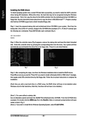
... installed under Windows once for the SATA controller from the Windows installation disk to install the RAID drivers. Boot from the menu. Your system will not have to be recognized during OS installation. From the CD-ROM drive (example: D:\) double click the MENU.exe file in your system. GA-8VM800M Motherboard - 68 - English Installing the RAID drivers To install operating system onto a serial ATA hard disk successfully, you need to install a third party SCSI or RAID driver" message, then supply serial ATA controller driver...
... installed under Windows once for the SATA controller from the Windows installation disk to install the RAID drivers. Boot from the menu. Your system will not have to be recognized during OS installation. From the CD-ROM drive (example: D:\) double click the MENU.exe file in your system. GA-8VM800M Motherboard - 68 - English Installing the RAID drivers To install operating system onto a serial ATA hard disk successfully, you need to install a third party SCSI or RAID driver" message, then supply serial ATA controller driver...
User Manual
Page 69
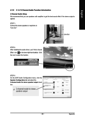
Click the icon to "Line Out." Line Out STEP 2: After installing the audio driver, you use speakers with amplifier to get the best sound effect if the stereo output is applied. STEP 1: Connect the stereo speakers or earphone to select the function. English 4-1-5 2 / 4 / 6 Channel Audio Function Introduction 2 Channel Audio Setup We recommend that you 'll find a Sound Effect icon on the lower right hand taskbar. STEP 3: On the AC97 Audio Configuration menu, click the Speaker Configuration tab and select the 2-channel mode for stereo speaker output check box. - 69 - Appendix
Click the icon to "Line Out." Line Out STEP 2: After installing the audio driver, you use speakers with amplifier to get the best sound effect if the stereo output is applied. STEP 1: Connect the stereo speakers or earphone to select the function. English 4-1-5 2 / 4 / 6 Channel Audio Function Introduction 2 Channel Audio Setup We recommend that you 'll find a Sound Effect icon on the lower right hand taskbar. STEP 3: On the AC97 Audio Configuration menu, click the Speaker Configuration tab and select the 2-channel mode for stereo speaker output check box. - 69 - Appendix
User Manual
Page 74
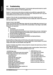
... updating BIOS. gate A20 failure 7 beeps Processor exception interrupt error 8 beeps Display memory read/write failure 9 beeps ROM checksum error 10 beeps CMOS shutdown register read/write error 11 beeps Cache memory bad AWARD BIOS Beep Codes 1 short: System boots successfully 2 short: CMOS setting error 1 long 1 short: DRAM or M/B error 1 long 2 short: Monitor or display card error 1 long 3 short: Keyboard error 1 long 9 short: BIOS ROM error Continuous long beeps: DRAM error Continuous short beeps: Power error GA-8VM800M Motherboard - 74 - Please press Ctrl and F1 keys after entering...
... updating BIOS. gate A20 failure 7 beeps Processor exception interrupt error 8 beeps Display memory read/write failure 9 beeps ROM checksum error 10 beeps CMOS shutdown register read/write error 11 beeps Cache memory bad AWARD BIOS Beep Codes 1 short: System boots successfully 2 short: CMOS setting error 1 long 1 short: DRAM or M/B error 1 long 2 short: Monitor or display card error 1 long 3 short: Keyboard error 1 long 9 short: BIOS ROM error Continuous long beeps: DRAM error Continuous short beeps: Power error GA-8VM800M Motherboard - 74 - Please press Ctrl and F1 keys after entering...


