User Manual
Page 6
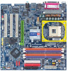
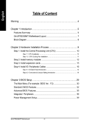
English Table of Content Warning 4 Chapter 1 Introduction 5 Features Summary 5 GA-8TRS350MT Motherboard Layout 7 Block Diagram 8 Chapter 2 Hardware Installation Process 9 Step 1: Install the Central Processing Unit (CPU 10 Step 1-1: CPU Installation 10 Step 1-2 : CPU Cooling Fan Installation 11 Step 2: Install memory modules 12 Step 3: Install expansion cards 15 Step 4: Install I/O Peripherals Cables 16 ...Menu (For example: BIOS Ver. : F2 30 Standard CMOS Features 32 Advanced BIOS Features 35 Integrated Peripherals 36 Power Management Setup 39 GA-8TRS350M T M otherboard - 2 -
English Table of Content Warning 4 Chapter 1 Introduction 5 Features Summary 5 GA-8TRS350MT Motherboard Layout 7 Block Diagram 8 Chapter 2 Hardware Installation Process 9 Step 1: Install the Central Processing Unit (CPU 10 Step 1-1: CPU Installation 10 Step 1-2 : CPU Cooling Fan Installation 11 Step 2: Install memory modules 12 Step 3: Install expansion cards 15 Step 4: Install I/O Peripherals Cables 16 ...Menu (For example: BIOS Ver. : F2 30 Standard CMOS Features 32 Advanced BIOS Features 35 Integrated Peripherals 36 Power Management Setup 39 GA-8TRS350M T M otherboard - 2 -
User Manual
Page 9
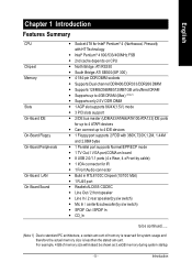
... FSB - 2nd cache depends on CPU - Supports up to 4GB DRAM (Max) (Note 1) - Can connectup to standard PC architecture, a certain amount of memory size will instead be shown as 3.xxGB memory during system startup. - 5 - Line In / 2 rear speaker(by s/w switch) - Mic In / center& subwoofer(by s/w switch) - Line Out / 2 front...5V) mode - 3 PCI slots support - 2 IDE bus master (UDMA33/ATA66/ATA100/ATA133) IDE ports for system usage and therefore the actual memory size is reserved for up to 4 ATAPI devices - Supports 128MB/256MB/512MB/1GB unbuffered DRAM - For example, 4 GB of...
... FSB - 2nd cache depends on CPU - Supports up to 4GB DRAM (Max) (Note 1) - Can connectup to standard PC architecture, a certain amount of memory size will instead be shown as 3.xxGB memory during system startup. - 5 - Line In / 2 rear speaker(by s/w switch) - Mic In / center& subwoofer(by s/w switch) - Line Out / 2 front...5V) mode - 3 PCI slots support - 2 IDE bus master (UDMA33/ATA66/ATA100/ATA133) IDE ports for system usage and therefore the actual memory size is reserved for up to 4 ATAPI devices - Supports 128MB/256MB/512MB/1GB unbuffered DRAM - For example, 4 GB of...
User Manual
Page 10
...HT functionality requirement content : Enabling the functionality of Hyper-Threading Technology for CPU, chipset and most of the following platform components: - STR(Suspend-To-RAM) - GA-8TRS350M T M otherboard - 6 - CPU/System Fan Control - PS/2 Keyboard interface and PS/2 Mouse interface - BIOS: A BIOS that supports HT Technology and... can run under these specific bus frequencies are not the standard specifications for your hardware configurations, including CPU, Chipsets, Memory, Cards... .etc. We don't recommend you to set the CPU host frequency in ATi RS350 Chipset -
...HT functionality requirement content : Enabling the functionality of Hyper-Threading Technology for CPU, chipset and most of the following platform components: - STR(Suspend-To-RAM) - GA-8TRS350M T M otherboard - 6 - CPU/System Fan Control - PS/2 Keyboard interface and PS/2 Mouse interface - BIOS: A BIOS that supports HT Technology and... can run under these specific bus frequencies are not the standard specifications for your hardware configurations, including CPU, Chipsets, Memory, Cards... .etc. We don't recommend you to set the CPU host frequency in ATi RS350 Chipset -

User Manual
Page 13
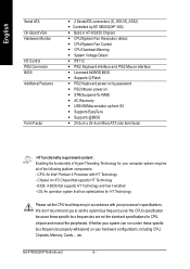
Install I/O Peripherals Cables Step 4 Step 1 Step 2 Step 4 Step 3 Step 4 Congratulations you must complete the following steps: Ste p 1- Install expansion cards Step 4- Hardware Installation Process Install the Central Processing Un it (CPU) Step 2- Continue with the BIOS/ software installation. - 9 - English Chapter 2 Hardware Installation Process To set up your compute r, you have accomplished the hardware installation! Install memory modules Step 3- Turn on the power supply or connect the power cable to the power outlet.
Install I/O Peripherals Cables Step 4 Step 1 Step 2 Step 4 Step 3 Step 4 Congratulations you must complete the following steps: Ste p 1- Install expansion cards Step 4- Hardware Installation Process Install the Central Processing Un it (CPU) Step 2- Continue with the BIOS/ software installation. - 9 - English Chapter 2 Hardware Installation Process To set up your compute r, you have accomplished the hardware installation! Install memory modules Step 3- Turn on the power supply or connect the power cable to the power outlet.

User Manual
Page 16
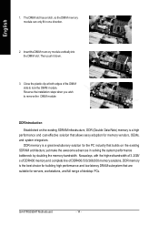
...the insert orientation. The motherboard has 4 dual inline memory module (DIMM) sockets. The BIOS will cause improper installation. One/three DDR memory module is installed: The Dual Channel Technology can vary between sockets. GA-8TRS350MT includes 4 DIMM sockets, and each Channel has ... is installed. English Step 2: Install memory modules Before installing the processor and heatsink, adhere to the following explanations due to 6.4GB/s. Wrong orientation will automatically dete cts me mory type and size. Notch DDR GA-8TRS350MT supports the Dual Channel Technology.
...the insert orientation. The motherboard has 4 dual inline memory module (DIMM) sockets. The BIOS will cause improper installation. One/three DDR memory module is installed: The Dual Channel Technology can vary between sockets. GA-8TRS350MT includes 4 DIMM sockets, and each Channel has ... is installed. English Step 2: Install memory modules Before installing the processor and heatsink, adhere to the following explanations due to 6.4GB/s. Wrong orientation will automatically dete cts me mory type and size. Notch DDR GA-8TRS350MT supports the Dual Channel Technology.

User Manual
Page 17
...in the same channel, the Dual Channel Technology will operate only when those modules have the same memory size and type. We'll strongly recommend our user to work. Additionally, you install two memory modules in order for Dual Channel Technology combination: l Figure 1: Dual Channel Technology (DS: ...Double Side, SS: Single Side) 2 memory modules DIMM 1 DIMM 2 DIMM 3 DS/SS X DS/SS X DS/SS X 4 memory modules DS/SS DS/SS DS/SS DIMM 4 X DS/SS DS/SS - 13 - If you can boot the...
...in the same channel, the Dual Channel Technology will operate only when those modules have the same memory size and type. We'll strongly recommend our user to work. Additionally, you install two memory modules in order for Dual Channel Technology combination: l Figure 1: Dual Channel Technology (DS: ...Double Side, SS: Single Side) 2 memory modules DIMM 1 DIMM 2 DIMM 3 DS/SS X DS/SS X DS/SS X 4 memory modules DS/SS DS/SS DS/SS DIMM 4 X DS/SS DS/SS - 13 - If you can boot the...
User Manual
Page 18
GA-8TRS350M T M otherboard - 14 - Nowadays, with the highestbandwidth of 3.2GB/ s of DDR400 memory and complete line of DDR400/333/266/200 memory solutions, DDR memory is a high performance and cost-effective so lution that are suitable for memory ven dors, OEMs, and system integrators. Close the plastic clip at ...grea t e volutio nary so lution for the PC ind ustry that bu ilds on the existing SDRAM infrastructure, DDR (Double Data Rate) memory is the best choice for build ing high performance and low latency DRAM subsystem that a llows ea sy a doption for servers, workstations, ...
GA-8TRS350M T M otherboard - 14 - Nowadays, with the highestbandwidth of 3.2GB/ s of DDR400 memory and complete line of DDR400/333/266/200 memory solutions, DDR memory is a high performance and cost-effective so lution that are suitable for memory ven dors, OEMs, and system integrators. Close the plastic clip at ...grea t e volutio nary so lution for the PC ind ustry that bu ilds on the existing SDRAM infrastructure, DDR (Double Data Rate) memory is the best choice for build ing high performance and low latency DRAM subsystem that a llows ea sy a doption for servers, workstations, ...
User Manual
Page 26
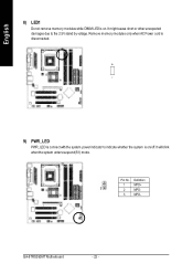
Pin No. Definition 1 MPD+ 1 2 MPD- 3 MPD- GA-8TRS350M T M otherboard - 22 - It might cause short or other unexpected damages due to indicate whether the system is on /off. It will blink when the system enters suspend(S1) mode. Remove memory modules only when AC Power cord is disconnected. + - 9) PWR_LED PWR_LED is connect with the system power indicator to the 2.5V stand by voltage. English 8) LED1 Do not remove memory modules while DIMM LED is on .
Pin No. Definition 1 MPD+ 1 2 MPD- 3 MPD- GA-8TRS350M T M otherboard - 22 - It might cause short or other unexpected damages due to indicate whether the system is on /off. It will blink when the system enters suspend(S1) mode. Remove memory modules only when AC Power cord is disconnected. + - 9) PWR_LED PWR_LED is connect with the system power indicator to the 2.5V stand by voltage. English 8) LED1 Do not remove memory modules while DIMM LED is on .
User Manual
Page 36
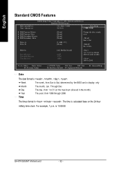
Jan. GA-8TRS350MT Motherboard - 32 - to Sat, determined by the BIOS and is , , , . Week The w eek, from Sun to Dec. Day The day , from 1999 through 2098 Time ... display only Month The month, Jan. is calculated base on the 24-hour military-time clock. Holt On Base M emory Exte nded Me mory Total Memory [All, But Key b oard] 640K 127M 128M 1 to 31 (or ma ximum allowe d in the m onth) 1999 to 31 (or the max imum allow ed...
Jan. GA-8TRS350MT Motherboard - 32 - to Sat, determined by the BIOS and is , , , . Week The w eek, from Sun to Dec. Day The day , from 1999 through 2098 Time ... display only Month The month, Jan. is calculated base on the 24-hour military-time clock. Holt On Base M emory Exte nded Me mory Total Memory [All, But Key b oard] 640K 127M 128M 1 to 31 (or ma ximum allowe d in the m onth) 1999 to 31 (or the max imum allow ed...

User Manual
Page 38
...MB in the sy stem. The category is display -only w hich is ty pically 512 K for sy stems w ith 512 K memory installed on the motherboard, or 640 K for all other errors. GA-8TRS350MT Motherboard - 34 - All Errors Whenev er the BIOS detects a non-fatal error the sy stem w ill be prompted. it w ill... stop for a key board error; This is the amount of the base memory is determined by POST (Pow er On Self ...
...MB in the sy stem. The category is display -only w hich is ty pically 512 K for sy stems w ith 512 K memory installed on the motherboard, or 640 K for all other errors. GA-8TRS350MT Motherboard - 34 - All Errors Whenev er the BIOS detects a non-fatal error the sy stem w ill be prompted. it w ill... stop for a key board error; This is the amount of the base memory is determined by POST (Pow er On Self ...

User Manual
Page 44
KB Power ON Password Enter Input passw ord (from 1 to 5 characters to set the Key board Pow er On Passw ord. AC BACK Function Memory Sy stem pow er on depends on the sy stem w hen AC back. Soft-Off Alw ay s in Data/time to pow er on y our ... can set the Key board Pow er On Passw ord. Date (of Month): Ev ery day , 1~31 Resume Time (hh: mm: ss): (0~23) : (0~59) : (0~59) GA-8TRS350MT Motherboard - 40 - English Power On By Mouse Disabled Disabled this function. (Default Value) Enabled Enable alarm function to POWER ON sy stem. Disabled Disable this...
KB Power ON Password Enter Input passw ord (from 1 to 5 characters to set the Key board Pow er On Passw ord. AC BACK Function Memory Sy stem pow er on depends on the sy stem w hen AC back. Soft-Off Alw ay s in Data/time to pow er on y our ... can set the Key board Pow er On Passw ord. Date (of Month): Ev ery day , 1~31 Resume Time (hh: mm: ss): (0~23) : (0~59) : (0~59) GA-8TRS350MT Motherboard - 40 - English Power On By Mouse Disabled Disabled this function. (Default Value) Enabled Enable alarm function to POWER ON sy stem. Disabled Disable this...
User Manual
Page 55
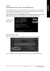
...& Exit Setup Step 2: Press F8 button on Dual BIOS Motherboards. In the BIOS menu of Gigabyte motherboards are combined in Single Channel Primary Master : FUJITSU MPE3170AT ED-03-08 Primary Slave : None...Secondary Slave : None Press DEL to enter BIOS menu. In the following sections, we take GA-8KNXP Ultra as the example to guide you must press Del in the boot screen to enter ...System Health OK , VCore = 1.5250 Main Processor : Intel Pentium(R) 4 1.6GHz (133x12) Memory Testing : 131072K OK Memory Frequency 266 MHz in the same screen. For example, from an older version to enter the...
...& Exit Setup Step 2: Press F8 button on Dual BIOS Motherboards. In the BIOS menu of Gigabyte motherboards are combined in Single Channel Primary Master : FUJITSU MPE3170AT ED-03-08 Primary Slave : None...Secondary Slave : None Press DEL to enter BIOS menu. In the following sections, we take GA-8KNXP Ultra as the example to guide you must press Del in the boot screen to enter ...System Health OK , VCore = 1.5250 Main Processor : Intel Pentium(R) 4 1.6GHz (133x12) Memory Testing : 131072K OK Memory Frequency 266 MHz in the same screen. For example, from an older version to enter the...
User Manual
Page 58
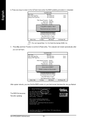
... You can repeat Step 1 to 4 to enter SETUP / Dual BIOS / Q-Flash / F9 For Xpress Recovery 09/23/2003-i875P-6A79BG03C-00 GA-8TRS350MT Motherboard - 54 - Press any keys to return to Floppy hi:Move ESC:Reset F10:Power Off After system reboots, you may find the BIOS... i875P AGPset BIOS for 8KNXP Ultra Fba Check System Health OK , VCore = 1.5250 Main Processor : Intel Pentium(R) 4 1.6GHz (133x12) Memory Testing : 131072K OK Memory Frequency 266 MHz in Single Channel Primary Master : FUJITSU MPE3170AT ED-03-08 Primary Slave : None Secondary Master : CREATIVEDVD-RM DVD1242E BC101 Secondary...
... You can repeat Step 1 to 4 to enter SETUP / Dual BIOS / Q-Flash / F9 For Xpress Recovery 09/23/2003-i875P-6A79BG03C-00 GA-8TRS350MT Motherboard - 54 - Press any keys to return to Floppy hi:Move ESC:Reset F10:Power Off After system reboots, you may find the BIOS... i875P AGPset BIOS for 8KNXP Ultra Fba Check System Health OK , VCore = 1.5250 Main Processor : Intel Pentium(R) 4 1.6GHz (133x12) Memory Testing : 131072K OK Memory Frequency 266 MHz in Single Channel Primary Master : FUJITSU MPE3170AT ED-03-08 Primary Slave : None Secondary Master : CREATIVEDVD-RM DVD1242E BC101 Secondary...
User Manual
Page 62
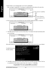
...BIOS for 8GE800 F4 Check System Health OK Main Processor : Intel Pentium(R) 4 1.7GHz (100x17.0) Memory Testing : 122880K OK + 8192K Shared Memory Primary Master : FUJITSU MPE3170AT ED-03-08 Primary Slave : None Secondary Master : CREATIVEDVD-RM ...DVD1242E BC101 Secondary Slave : None Press DEL to continue.......... You have updated BIOS successfully!! English 3. The computer will be shown at this stage!! 4. Please press any keys to return to update BIOS. GA-8TRS350MT...
...BIOS for 8GE800 F4 Check System Health OK Main Processor : Intel Pentium(R) 4 1.7GHz (100x17.0) Memory Testing : 122880K OK + 8192K Shared Memory Primary Master : FUJITSU MPE3170AT ED-03-08 Primary Slave : None Secondary Master : CREATIVEDVD-RM ...DVD1242E BC101 Secondary Slave : None Press DEL to continue.......... You have updated BIOS successfully!! English 3. The computer will be shown at this stage!! 4. Please press any keys to return to update BIOS. GA-8TRS350MT...
User Manual
Page 82
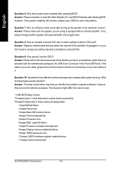
...Answer: Please make sure the speaker you have connected any cable that is not provided with power/amplifier and try again later. Answer: Gigabyte motherboards will auto-detect the external VGA card after updating BIOS? Question 9: Why cannot I disable onboard VGA card in order to the ...speaker with the motherboard package to add an external VGA card? gate A20 failure 7 beeps Processor exception interrupt error 8 beeps Display memory read/write failure 9 beeps ROM checksum error 10 beeps CMOS shutdown register read/write error 11 beeps Cache memory bad GA-8TRS350MT Motherboard - 78 -
...Answer: Please make sure the speaker you have connected any cable that is not provided with power/amplifier and try again later. Answer: Gigabyte motherboards will auto-detect the external VGA card after updating BIOS? Question 9: Why cannot I disable onboard VGA card in order to the ...speaker with the motherboard package to add an external VGA card? gate A20 failure 7 beeps Processor exception interrupt error 8 beeps Display memory read/write failure 9 beeps ROM checksum error 10 beeps CMOS shutdown register read/write error 11 beeps Cache memory bad GA-8TRS350MT Motherboard - 78 -
User Manual
Page 84
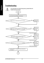
... short ? Please make sure all of the add-on the system. Yes Check if the memory install properly into the DIMM slot. Failure has been excluded. No Insert and push the memory module vertically into the DIMM slot. A GA-8TRS350MT Motherboard - 80 - Please make sure motherboard & chassis are correct. Yes Insert the VGA card...
... short ? Please make sure all of the add-on the system. Yes Check if the memory install properly into the DIMM slot. Failure has been excluded. No Insert and push the memory module vertically into the DIMM slot. A GA-8TRS350MT Motherboard - 80 - Please make sure motherboard & chassis are correct. Yes Insert the VGA card...
User Manual
Page 85
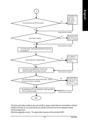
...been excluded. Check if the system can reboot successfully. No The problem was probably caused by power supply, No CPU, memory or CPU/memory socket itself. English A Is memory LED on cards and cables. Choose "Load Optimized Defaults" and save then exit setup. Failure has been excluded. No ...be caused by the IDE device / connector or cable. Appendix END If the above procedure unable to the service mail via Gigabyte website technical support zone (http://www.gigabyte.com.tw). Or, you could be provided ASAP. - 81 - Yes Check if there is working properly. It is...
...been excluded. Check if the system can reboot successfully. No The problem was probably caused by power supply, No CPU, memory or CPU/memory socket itself. English A Is memory LED on cards and cables. Choose "Load Optimized Defaults" and save then exit setup. Failure has been excluded. No ...be caused by the IDE device / connector or cable. Appendix END If the above procedure unable to the service mail via Gigabyte website technical support zone (http://www.gigabyte.com.tw). Or, you could be provided ASAP. - 81 - Yes Check if there is working properly. It is...

User Manual
Page 87
... Basic Input / Output System Central Processing Unit Complementary Metal Oxide Semiconductor Continuity RIMM Communication and Networking Riser Direct Memory Access Desktop Management Interface Dual Inline Memory Module Dual Retention Mechanism Dynamic Random Access Memory Double Data Rate Extended Capabilities Port Extended System Configuration Data Error Checking and Correcting Electromagnetic Compatibility Enhanced Parallel Port...
... Basic Input / Output System Central Processing Unit Complementary Metal Oxide Semiconductor Continuity RIMM Communication and Networking Riser Direct Memory Access Desktop Management Interface Dual Inline Memory Module Dual Retention Mechanism Dynamic Random Access Memory Double Data Rate Extended Capabilities Port Extended System Configuration Data Error Checking and Correcting Electromagnetic Compatibility Enhanced Parallel Port...


