User Manual
Page 6
English Table of Content Warning 4 Chapter 1 Introduction 5 Features Summary 5 GA-8TRS350MT Motherboard Layout 7 Block Diagram 8 Chapter 2 Hardware Installation Process 9 Step 1: Install the Central Processing Unit (CPU 10 Step 1-1: CPU Installation 10 Step... cards 15 Step 4: Install I/O Peripherals Cables 16 Step 4-1: I/O Back Panel Introduction 16 Step 4-2: Connectors & Jumper Setting Introduction 18 Chapter 3 BIOS Setup 29 The Main Menu (For example: BIOS Ver. : F2 30 Standard CMOS Features 32 Advanced BIOS Features 35 Integrated Peripherals 36 Power Management Setup 39...
English Table of Content Warning 4 Chapter 1 Introduction 5 Features Summary 5 GA-8TRS350MT Motherboard Layout 7 Block Diagram 8 Chapter 2 Hardware Installation Process 9 Step 1: Install the Central Processing Unit (CPU 10 Step 1-1: CPU Installation 10 Step... cards 15 Step 4: Install I/O Peripherals Cables 16 Step 4-1: I/O Back Panel Introduction 16 Step 4-2: Connectors & Jumper Setting Introduction 18 Chapter 3 BIOS Setup 29 The Main Menu (For example: BIOS Ver. : F2 30 Standard CMOS Features 32 Advanced BIOS Features 35 Integrated Peripherals 36 Power Management Setup 39...

User Manual
Page 7
Table of Content English PnP/PCI Configurations 41 PC Health Status 42 Frequency/Voltage Control 43 Top Performance 44 Load Fail-Safe Defaults 45 Load Optimized Defaults 45 Set Supervisor/User Password 46 Save & Exit Setup 47 Exit Without Saving 47 Chapter 4 Technical Reference 49 @ BIOSTM Introduction 49 Flash BIOS Method Introduction 50 2- / 4- / 6-Channel Audio Function Introduction 61 Jack-Sensing Introduction 67 Xpress Recovery Introduction 69 Chapter 5 Appendix 73 - 3 -
Table of Content English PnP/PCI Configurations 41 PC Health Status 42 Frequency/Voltage Control 43 Top Performance 44 Load Fail-Safe Defaults 45 Load Optimized Defaults 45 Set Supervisor/User Password 46 Save & Exit Setup 47 Exit Without Saving 47 Chapter 4 Technical Reference 49 @ BIOSTM Introduction 49 Flash BIOS Method Introduction 50 2- / 4- / 6-Channel Audio Function Introduction 61 Jack-Sensing Introduction 67 Xpress Recovery Introduction 69 Chapter 5 Appendix 73 - 3 -
User Manual
Page 10
...'t recommend you to set the CPU host frequency in ATi RS350 Chipset - Supports Q-Flash - PS/2 Keyboard power on - Supports @BIOS - 24.5cm x 24.4cm Micro ATX size form factor HT functionality requirement content : Enabling the functionality of Hyper-Threading Technology for ... system can run under these specific bus frequencies are not the standard specifications for CPU, chipset and most of the following platform components: - GA-8TRS350M T M otherboard - 6 - Build in accordance with HT Technology - OS: An operation system that has optimizations for your hardware configurations...
...'t recommend you to set the CPU host frequency in ATi RS350 Chipset - Supports Q-Flash - PS/2 Keyboard power on - Supports @BIOS - 24.5cm x 24.4cm Micro ATX size form factor HT functionality requirement content : Enabling the functionality of Hyper-Threading Technology for ... system can run under these specific bus frequencies are not the standard specifications for CPU, chipset and most of the following platform components: - GA-8TRS350M T M otherboard - 6 - Build in accordance with HT Technology - OS: An operation system that has optimizations for your hardware configurations...
User Manual
Page 11
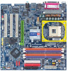
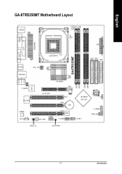
Introduction English GA-8TRS350MT Motherboard Layout KB_MS C PU_FAN LED1 ATX TV Out MOSHSINK VGA LPT GA-8TRS350MT DDR1 DDR2 DDR3 DDR4 SOC KET478 IDE2 IDE1 FDD R_U SB ATX_12V U SB_LAN MIC_IN LINE_OUT LINE_IN IT8712 F_AU DIO R TL 8 1 00 C C ODEC C D_IN ATi RS350 AGP 2X_DE T SYS _FAN C OM A PCI1 PCI2 BAT PCI3 BIOS F_U SB2 ATi SB300 (IXP 300) S_ATA1 S_ATA2 IR F_U SB1 F_PAN EL PWR_LED SPDIF_IO C LR_C M OS - 7 -
Introduction English GA-8TRS350MT Motherboard Layout KB_MS C PU_FAN LED1 ATX TV Out MOSHSINK VGA LPT GA-8TRS350MT DDR1 DDR2 DDR3 DDR4 SOC KET478 IDE2 IDE1 FDD R_U SB ATX_12V U SB_LAN MIC_IN LINE_OUT LINE_IN IT8712 F_AU DIO R TL 8 1 00 C C ODEC C D_IN ATi RS350 AGP 2X_DE T SYS _FAN C OM A PCI1 PCI2 BAT PCI3 BIOS F_U SB2 ATi SB300 (IXP 300) S_ATA1 S_ATA2 IR F_U SB1 F_PAN EL PWR_LED SPDIF_IO C LR_C M OS - 7 -

User Manual
Page 13
Hardware Installation Process Install the Central Processing Un it (CPU) Step 2- Install memory modules Step 3- Continue with the BIOS/ software installation. - 9 - Install I/O Peripherals Cables Step 4 Step 1 Step 2 Step 4 Step 3 Step 4 Congratulations you must complete the following steps: Ste p 1- Install expansion cards Step 4- English Chapter 2 Hardware Installation Process To set up your compute r, you have accomplished the hardware installation! Turn on the power supply or connect the power cable to the power outlet.
Hardware Installation Process Install the Central Processing Un it (CPU) Step 2- Install memory modules Step 3- Continue with the BIOS/ software installation. - 9 - Install I/O Peripherals Cables Step 4 Step 1 Step 2 Step 4 Step 3 Step 4 Congratulations you must complete the following steps: Ste p 1- Install expansion cards Step 4- English Chapter 2 Hardware Installation Process To set up your compute r, you have accomplished the hardware installation! Turn on the power supply or connect the power cable to the power outlet.

User Manual
Page 16
... DIMM socket. Notch DDR GA-8TRS350MT supports the Dual Channel Technology. After operating the Dual Channel Technology, the bandwidth of ATi chipset specifications. 1. One/three DDR memory module is ON, do not install/remove DIMM from socket. The BIOS will cause improper installation.... The motherboard has 4 dual inline memory module (DIMM) sockets. English Step 2: Install memory modules Before installing the processor and heatsink, adhere to the no tch. GA-8TRS350MT includes 4 DIMM sockets, and each...
... DIMM socket. Notch DDR GA-8TRS350MT supports the Dual Channel Technology. After operating the Dual Channel Technology, the bandwidth of ATi chipset specifications. 1. One/three DDR memory module is ON, do not install/remove DIMM from socket. The BIOS will cause improper installation.... The motherboard has 4 dual inline memory module (DIMM) sockets. English Step 2: Install memory modules Before installing the processor and heatsink, adhere to the no tch. GA-8TRS350MT includes 4 DIMM sockets, and each...
User Manual
Page 19
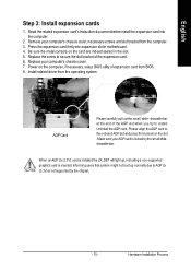
...the AGP card to AGP 2x (3.3V) is not supported by the small whitedrawable bar. Be sure the metalcontacts on the computer, if necessary, setup BIOS utility of the expansion card. 6. Install related driver from the computer. 3. Informing users that system might not boot up , indicating a non-supported...pull outthe small white- drawable bar at the end of the AGP slot when you try to secure the slot bracket of expansion card from BIOS. 8. Replace the screw to install/ Uninstall the AGP card. Replace your computer's chassis cover, necessary screws and slot bracket from the operating ...
...the AGP card to AGP 2x (3.3V) is not supported by the small whitedrawable bar. Be sure the metalcontacts on the computer, if necessary, setup BIOS utility of the expansion card. 6. Install related driver from the computer. 3. Informing users that system might not boot up , indicating a non-supported...pull outthe small white- drawable bar at the end of the AGP slot when you try to secure the slot bracket of expansion card from BIOS. 8. Replace the screw to install/ Uninstall the AGP card. Replace your computer's chassis cover, necessary screws and slot bracket from the operating ...
User Manual
Page 25
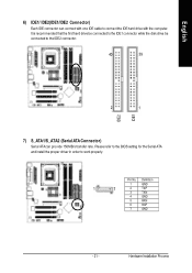
Please refer to the BIOS setting for the Serial ATA and install the proper driver in order to connect the IDE hard drive with one IDE cable to work properly. ...
Please refer to the BIOS setting for the Serial ATA and install the proper driver in order to connect the IDE hard drive with one IDE cable to work properly. ...
User Manual
Page 33
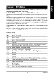
...You can be reset to a new BIOS, either Gigabyte's Q-Flash or @BIOS utility can enter the BIOS setup screen by pressing "Ctrl + F1". BIOS Setup Q-Flash allows the user to quickly and easily update or backup BIOS without entering the operating sy stem. @BIOS is recommended that you wish to upgrade ...in the left hand Move to activate certain system features. Exit current page and return to DOS before upgrading BIOS but directly download and update BIOS from BIOS default table Load the Optimized Defaults Q-Flash function System Information Save all the CMOS changes, only for Option ...
...You can be reset to a new BIOS, either Gigabyte's Q-Flash or @BIOS utility can enter the BIOS setup screen by pressing "Ctrl + F1". BIOS Setup Q-Flash allows the user to quickly and easily update or backup BIOS without entering the operating sy stem. @BIOS is recommended that you wish to upgrade ...in the left hand Move to activate certain system features. Exit current page and return to DOS before upgrading BIOS but directly download and update BIOS from BIOS default table Load the Optimized Defaults Q-Flash function System Information Save all the CMOS changes, only for Option ...
User Manual
Page 34
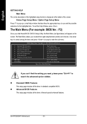
...Features This setup page includes all the items of the screen. l Advanced BI OS Features This setup page includes all the items in standard compatible BIOS. GA-8TRS350MT Motherboard - 30 - Status Page Setup Menu / Option Page Setup Menu Press F1 to pop up a small help window that describes the appropriate...select among the items and press to use and the possible selections for the highlighted item. The Main Menu (For example: BIOS Ver. : F2) Once you enterAward BIOS CMOS Setup Utility, the Main Menu (as figure below) will appear on -line description of the highlighted setup function is ...
...Features This setup page includes all the items of the screen. l Advanced BI OS Features This setup page includes all the items in standard compatible BIOS. GA-8TRS350MT Motherboard - 30 - Status Page Setup Menu / Option Page Setup Menu Press F1 to pop up a small help window that describes the appropriate...select among the items and press to use and the possible selections for the highlighted item. The Main Menu (For example: BIOS Ver. : F2) Once you enterAward BIOS CMOS Setup Utility, the Main Menu (as figure below) will appear on -line description of the highlighted setup function is ...

User Manual
Page 35
... limit access to the system and Setup, or just to CMOS and exit setup. l Power Manag ement Setup This setup page includes all onboard peripherals. BIOS Setup English l Integrated Peripherals This setup page includes all the items of Green function features. l Set Supervisor password Change, set , or disable password. l Set User...
... limit access to the system and Setup, or just to CMOS and exit setup. l Power Manag ement Setup This setup page includes all onboard peripherals. BIOS Setup English l Integrated Peripherals This setup page includes all the items of Green function features. l Set Supervisor password Change, set , or disable password. l Set User...
User Manual
Page 36
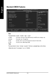
... month, Jan. to Dec. Day The day , from 1 to 31 (or the max imum allow ed in the m onth) 1999 to Sat, determined by the BIOS and is , , , . For example, 1 p.m. Through Dec. English Standard CMOS Features Date (mm:dd :y y ) Time (hh:mm :ss) CMOS Setup Utility -Co py right (C) 1984 -2004... M aster } IDE Secondary Slave Driv e A Driv e B [No ne] [No ne] [No ne] [No ne] [1.44M, 3.5"] [No ne] Change the day , mon th, year Sun. Jan. GA-8TRS350MT Motherboard - 32 -
... month, Jan. to Dec. Day The day , from 1 to 31 (or the max imum allow ed in the m onth) 1999 to Sat, determined by the BIOS and is , , , . For example, 1 p.m. Through Dec. English Standard CMOS Features Date (mm:dd :y y ) Time (hh:mm :ss) CMOS Setup Utility -Co py right (C) 1984 -2004... M aster } IDE Secondary Slave Driv e A Driv e B [No ne] [No ne] [No ne] [No ne] [1.44M, 3.5"] [No ne] Change the day , mon th, year Sun. Jan. GA-8TRS350MT Motherboard - 32 -
User Manual
Page 37
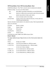
BIOS Setup The four options are used and the sy stem w il skip the automatic detection step and allow for faster sy stem start up. No ...-sided driv e; 1.44M by te capacity . 3.5 inch double-sided driv e; 2.88M by te capacity . - 33 - Manual User can use one of three methods: Auto Allow s BIOS to automatically detect IDE dev ices during POST(default) None Select this if no IDE dev ices are : CHS/LBA/Large/Auto(default:Auto) Hard...
BIOS Setup The four options are used and the sy stem w il skip the automatic detection step and allow for faster sy stem start up. No ...-sided driv e; 1.44M by te capacity . 3.5 inch double-sided driv e; 2.88M by te capacity . - 33 - Manual User can use one of three methods: Auto Allow s BIOS to automatically detect IDE dev ices during POST(default) None Select this if no IDE dev ices are : CHS/LBA/Large/Auto(default:Auto) Hard...

User Manual
Page 38
... Disk/Key Memory The sy stem boot w ill not stop if an error is present during pow er up. Base Memory The POST of the BIOS w ill determine the amount of memory located abov e 1 MB in the sy stem. it w ill stop for a key board error; The category is display -only... (Pow er On Self Test) of the base memory is the amount of base (or conv entional) memory installed in the CPU's memory address map. GA-8TRS350MT Motherboard - 34 - The sy stem boot w ill not stop for a disk error; NO Errors The system boot will not stop for any error that may...
... Disk/Key Memory The sy stem boot w ill not stop if an error is present during pow er up. Base Memory The POST of the BIOS w ill determine the amount of memory located abov e 1 MB in the sy stem. it w ill stop for a key board error; The category is display -only... (Pow er On Self Test) of the base memory is the amount of base (or conv entional) memory installed in the CPU's memory address map. GA-8TRS350MT Motherboard - 34 - The sy stem boot w ill not stop for a disk error; NO Errors The system boot will not stop for any error that may...

User Manual
Page 39
.... Select y our boot dev ice priority by USB-CDROM. Select y our boot dev ice priority by LS120. Select y our boot dev ice priority by Floppy . BIOS Setup Floppy LS120 Hard Disk CDROM ZIP USB-FDD USB-ZIP USB-CDROM USB-HDD LAN Disabled Select y our boot dev ice priority by Disabled... boot dev ice priority by Hard Disk. Select y our boot dev ice priority by LAN. Press to select the boot dev ice priority . English Advanced BIOS Features CMOS Setup Utility -Co py right (C) 1984 -2004 Aw ard Software Advanced BI OS Features } Hard Disk Bo ot Prio rity First Boot De...
.... Select y our boot dev ice priority by USB-CDROM. Select y our boot dev ice priority by LS120. Select y our boot dev ice priority by Floppy . BIOS Setup Floppy LS120 Hard Disk CDROM ZIP USB-FDD USB-ZIP USB-CDROM USB-HDD LAN Disabled Select y our boot dev ice priority by Disabled... boot dev ice priority by Hard Disk. Select y our boot dev ice priority by LAN. Press to select the boot dev ice priority . English Advanced BIOS Features CMOS Setup Utility -Co py right (C) 1984 -2004 Aw ard Software Advanced BI OS Features } Hard Disk Bo ot Prio rity First Boot De...
User Manual
Page 41
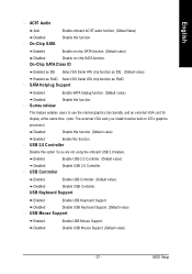
... time. (note: The ex ternal VGA card y ou install must be built on -chip SATA function. USB Keyboard Support Enabled Enable USB Key board Support. BIOS Setup USB Con troller Enabled Enable USB Controller. (Default v alue) Disabled Disable USB Controller. English AC97 Audio Auto Disabled On-Chip SATA Enable onboard AC...
... time. (note: The ex ternal VGA card y ou install must be built on -chip SATA function. USB Keyboard Support Enabled Enable USB Key board Support. BIOS Setup USB Con troller Enabled Enable USB Controller. (Default v alue) Disabled Disable USB Controller. English AC97 Audio Auto Disabled On-Chip SATA Enable onboard AC...
User Manual
Page 42
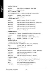
... Mode. ASKIR Set onboard I /O chip UART to ASKIR Mode. Half IR Function Duplex Half. (Default v alue) Full IR Function Duplex Full. Onboard Serial Port 1 Auto BIOS w ill automatically setup the port 1 address. 3F8/IRQ4 Enable onboard Serial port 1 and address is 3F8. (Default v alue) 2F8/IRQ3 Enable onboard Serial port 1 and... to inv oke the boot ROM of Onboard I/O chip. Disabled Disable onboard LPT port. 3BC/IRQ7 Enable onboard LPT port and address is 3BC/IRQ7. GA-8TRS350MT Motherboard - 38 -
... Mode. ASKIR Set onboard I /O chip UART to ASKIR Mode. Half IR Function Duplex Half. (Default v alue) Full IR Function Duplex Full. Onboard Serial Port 1 Auto BIOS w ill automatically setup the port 1 address. 3F8/IRQ4 Enable onboard Serial port 1 and address is 3F8. (Default v alue) 2F8/IRQ3 Enable onboard Serial port 1 and... to inv oke the boot ROM of Onboard I/O chip. Disabled Disable onboard LPT port. 3BC/IRQ7 Enable onboard LPT port and address is 3BC/IRQ7. GA-8TRS350MT Motherboard - 38 -

User Manual
Page 43
to S3. BIOS Setup Enter suspend if button is pressed less than 4 sec. USB Device Wake-up function. (Default Value) Disabled Disable this function. If use single color ...
to S3. BIOS Setup Enter suspend if button is pressed less than 4 sec. USB Device Wake-up function. (Default Value) Disabled Disable this function. If use single color ...

User Manual
Page 45
... PCI 2. Auto assign IRQ to PCI 2. (Default v alue) Set IRQ 3,4,5,7,9,10,11,12,14,15 to PCI 3. - 41 - Bus 0 Dev20 Func 2 Disp lay Cn trlr - BIOS Setup English PnP/PCI Configurations CMOS Setup Utility -Co py right (C) 1984 -2004 Aw ard Software PnP/PCI Con figurations PCI 1 IRQ Assig nment PCI...
... PCI 2. Auto assign IRQ to PCI 2. (Default v alue) Set IRQ 3,4,5,7,9,10,11,12,14,15 to PCI 3. - 41 - Bus 0 Dev20 Func 2 Disp lay Cn trlr - BIOS Setup English PnP/PCI Configurations CMOS Setup Utility -Co py right (C) 1984 -2004 Aw ard Software PnP/PCI Con figurations PCI 1 IRQ Assig nment PCI...
User Manual
Page 47
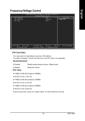
... y our sy stem broken. For pow er End-User use only ! - 43 - for FSB(Front Side Bus) frequency =400MHz, Set CPU Clock to 100~132. BIOS Setup English Frequency/Voltage Control CPU Clock Ratio Spre ad Spec trum CPU Clock CMOS Setup Utility -Co py right (C) 1984 -2004 Aw ard Software...
... y our sy stem broken. For pow er End-User use only ! - 43 - for FSB(Front Side Bus) frequency =400MHz, Set CPU Clock to 100~132. BIOS Setup English Frequency/Voltage Control CPU Clock Ratio Spre ad Spec trum CPU Clock CMOS Setup Utility -Co py right (C) 1984 -2004 Aw ard Software...


