Manual
Page 1
Table of Contents Configuring SATA Hard Drive(s) (Controller SiS 964 2 (1) Installing SATA hard drive(s) in your computer 2 (2) Configuring SATA controller mode and boot sequence in BIOS Setup 3 (3) Configuring RAID set in RAID BIOS 5 (4) Making a SATA controller driver disk 10 (5) Installing SATA controller driver during OS installation 12
Table of Contents Configuring SATA Hard Drive(s) (Controller SiS 964 2 (1) Installing SATA hard drive(s) in your computer 2 (2) Configuring SATA controller mode and boot sequence in BIOS Setup 3 (3) Configuring RAID set in RAID BIOS 5 (4) Making a SATA controller driver disk 10 (5) Installing SATA controller driver during OS installation 12
Manual
Page 2
... follow the steps below: ¤å (1) Install SATA hard drive(s) in your system. (2) Configure SATA controller mode and boot sequence in BIOS Setup. (3)* Configure RAID set in your computer Attach one end of the SATA signal cable to the rear of the SATA connector to identify ...the SATA controller for your motherboard. (1) Installing SATA hard drive(s) in RAID BIOS. (4) Make a floppy disk containing the SATA controller driver. (5) Install the SATA controller driver during OS installation. "*" Skip this step if you...
... follow the steps below: ¤å (1) Install SATA hard drive(s) in your system. (2) Configure SATA controller mode and boot sequence in BIOS Setup. (3)* Configure RAID set in your computer Attach one end of the SATA signal cable to the rear of the SATA connector to identify ...the SATA controller for your motherboard. (1) Installing SATA hard drive(s) in RAID BIOS. (4) Make a floppy disk containing the SATA controller driver. (5) Install the SATA controller driver during OS installation. "*" Skip this step if you...
Manual
Page 3
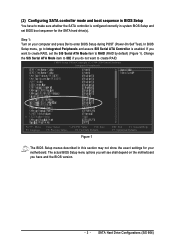
...Value F10: Save F5: Previous Values F6: Fail-Safe Defaults Figure 1 ESC: Exit F1: General Help F7: Optimized Defaults The BIOS Setup menus described in system BIOS Setup and set the SiS Serial ATA Mode item to create RAID. SATA Hard Drive Configurations (SiS 964) Change the SiS Serial ...have to make sure whether the SATA controller is enabled. (2) Configuring SATA controller mode and boot sequence in BIOS Setup You have and the BIOS version. - 3 - In BIOS Setup menu, go to enter BIOS Setup during POST (Power-On Self Test). Step 1: Turn on the motherboard you do not want to...
...Value F10: Save F5: Previous Values F6: Fail-Safe Defaults Figure 1 ESC: Exit F1: General Help F7: Optimized Defaults The BIOS Setup menus described in system BIOS Setup and set the SiS Serial ATA Mode item to create RAID. SATA Hard Drive Configurations (SiS 964) Change the SiS Serial ...have to make sure whether the SATA controller is enabled. (2) Configuring SATA controller mode and boot sequence in BIOS Setup You have and the BIOS version. - 3 - In BIOS Setup menu, go to enter BIOS Setup during POST (Power-On Self Test). Step 1: Turn on the motherboard you do not want to...
Manual
Page 4
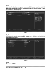
...drive onto which you intent to boot from CD-ROM after system restarts (Figure 3). CMOS Setup Utility-Copyright (C) 1984-2004 Award Software Advanced BIOS Features ` Hard Disk Boot Priority [Press Enter] First Boot Device [CDROM] ` Second Boot Device [Hard Disk] Third Boot Device [CDROM... Move F3: Language Enter: Select +/-/PU/PD: Value F10: Save F5: Previous Values F6: Fail-Safe Defaults Figure 3 Step 4: Save and exit BIOS Setup. CMOS Setup Utility-Copyright (C) 1984-2004 Award Software ¤å Hard Disk Boot Priority `` K L KL Figure 2 Step 3: Set First ...
...drive onto which you intent to boot from CD-ROM after system restarts (Figure 3). CMOS Setup Utility-Copyright (C) 1984-2004 Award Software Advanced BIOS Features ` Hard Disk Boot Priority [Press Enter] First Boot Device [CDROM] ` Second Boot Device [Hard Disk] Third Boot Device [CDROM... Move F3: Language Enter: Select +/-/PU/PD: Value F10: Save F5: Previous Values F6: Fail-Safe Defaults Figure 3 Step 4: Save and exit BIOS Setup. CMOS Setup Utility-Copyright (C) 1984-2004 Award Software ¤å Hard Disk Boot Priority `` K L KL Figure 2 Step 3: Set First ...

Manual
Page 5
... - 5 - Skip this step and proceed to Section 4 if you cannot enter the RAID BIOS correctly, assure that your SATA drives are properly installed. If you do not want to enter the RAID BIOS setup utility. Hit CTRL+S to create RAID. Disk Status window appears (refer to configure a RAID... array. (3) Configuring RAID set in RAID BIOS Enter the RAID BIOS setup utility to Figure 5). The SiS RAID BIOS Setting Utility - Step 1: After the POST memory test begins and before the operating system boot begins, look for ...
... - 5 - Skip this step and proceed to Section 4 if you cannot enter the RAID BIOS correctly, assure that your SATA drives are properly installed. If you do not want to enter the RAID BIOS setup utility. Hit CTRL+S to create RAID. Disk Status window appears (refer to configure a RAID... array. (3) Configuring RAID set in RAID BIOS Enter the RAID BIOS setup utility to Figure 5). The SiS RAID BIOS Setting Utility - Step 1: After the POST memory test begins and before the operating system boot begins, look for ...
Manual
Page 12
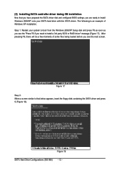
... your SATA hard drive with the SATA driver. Figure 17 Step 2: When a screen similar to that you have prepared the SATA driver disk and configured BIOS settings, you are ready to install Windows 2000/XP onto your system to install a 3rd party SCSI or RAID driver" message (Figure 17). The following...
... your SATA hard drive with the SATA driver. Figure 17 Step 2: When a screen similar to that you have prepared the SATA driver disk and configured BIOS settings, you are ready to install Windows 2000/XP onto your system to install a 3rd party SCSI or RAID driver" message (Figure 17). The following...
Manual
Page 4
...GA-8S661GXM-775 Motherboard Layout 6 Block Diagram ...7 Chapter 1 Hardware Installation 9 1-1 Considerations Prior to Installation 9 1-2 Feature Summary 10 1-3 Installation of the CPU and Heatsink 12 1-3-1 Installation of the CPU 12 1-3-2 Installation of the Heatsink 13 1-4 Installation of Memory 14 1-5 Installation of Expansion Cards 15 1-6 I/O Back Panel Introduction 16 1-7 Connectors Introduction 17 Chapter 2 BIOS... Setup 29 The Main Menu (For example: BIOS Ver. : F1 30 2-1 Standard CMOS Features 32 2-2 Advanced BIOS Features 34 2-3 ...
...GA-8S661GXM-775 Motherboard Layout 6 Block Diagram ...7 Chapter 1 Hardware Installation 9 1-1 Considerations Prior to Installation 9 1-2 Feature Summary 10 1-3 Installation of the CPU and Heatsink 12 1-3-1 Installation of the CPU 12 1-3-2 Installation of the Heatsink 13 1-4 Installation of Memory 14 1-5 Installation of Expansion Cards 15 1-6 I/O Back Panel Introduction 16 1-7 Connectors Introduction 17 Chapter 2 BIOS... Setup 29 The Main Menu (For example: BIOS Ver. : F1 30 2-1 Standard CMOS Features 32 2-2 Advanced BIOS Features 34 2-3 ...
Manual
Page 5
Chapter 3 Drivers Installation 49 3-1 Install Chipset Drivers 49 3-2 SoftwareApplications 50 3-3 Driver CD Information 50 3-4 Hardware Information 51 3-5 Contact Us ...51 Chapter 4 Appendix ...53 4-1 Unique Software Utilities 53 4-1-1 EasyTune 5 Introduction 53 4-1-2 Xpress Recovery2 Introduction 54 4-1-3 BIOS Flash Method Introduction 56 4-1-4 Serial ATA BIOS Setting Utility Introduction 65 4-1-5 2 / 4 / 6 Channel Audio Function Introduction 72 4-2 Troubleshooting 80 - 5 -
Chapter 3 Drivers Installation 49 3-1 Install Chipset Drivers 49 3-2 SoftwareApplications 50 3-3 Driver CD Information 50 3-4 Hardware Information 51 3-5 Contact Us ...51 Chapter 4 Appendix ...53 4-1 Unique Software Utilities 53 4-1-1 EasyTune 5 Introduction 53 4-1-2 Xpress Recovery2 Introduction 54 4-1-3 BIOS Flash Method Introduction 56 4-1-4 Serial ATA BIOS Setting Utility Introduction 65 4-1-5 2 / 4 / 6 Channel Audio Function Introduction 72 4-2 Troubleshooting 80 - 5 -

Manual
Page 6
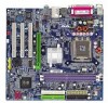
GA-8S661GXM-775 Motherboard Layout COMA LPT KB_MS ATX_12V COMB LGA775 CPU_FAN FDD ATX VGA GA-8S661GXM-775 DDR1 DDR2 USB LAN USB AUDIO F_AUDIO SiS 661GX AGP ICS1883 IT8705AF BIOS CODEC CD_IN SUR_CEN SPDIF_IO IDE2 IDE1 PCI1 CLR_CMOS PCI2 SiS 964 SYS _FAN SATA1 PCI3 BAT F_USB1 F_USB2 CI PWR_LED SATA0 F_PANEL - 6 -
GA-8S661GXM-775 Motherboard Layout COMA LPT KB_MS ATX_12V COMB LGA775 CPU_FAN FDD ATX VGA GA-8S661GXM-775 DDR1 DDR2 USB LAN USB AUDIO F_AUDIO SiS 661GX AGP ICS1883 IT8705AF BIOS CODEC CD_IN SUR_CEN SPDIF_IO IDE2 IDE1 PCI1 CLR_CMOS PCI2 SiS 964 SYS _FAN SATA1 PCI3 BAT F_USB1 F_USB2 CI PWR_LED SATA0 F_PANEL - 6 -
Manual
Page 7
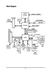
Block Diagram LGA775 Processor CPUCLK+/- (133MHz) AGP 4X/8X AGPCLK (66MHz) VGA Port Host Interface 266/333/400MHz DDR RAM SiS 661GX HCLK+/- (133MHz) 3 PCI ICS1883 SiS 964 133MHz 33 MHz 14.318 MHz 48 MHz 2 Serial ATA BIOS LPC BUS IT8705AF Floppy LPT Port AC97 Link PCICLK (33MHz) MIC LINE-IN LINE-OUT RJ45 AC97 CODEC 8 USB ATA33/66/100/ Ports 133 IDE Channels 24 MHz 33 MHz PS/2 KB/Mouse COM Ports - 7 -
Block Diagram LGA775 Processor CPUCLK+/- (133MHz) AGP 4X/8X AGPCLK (66MHz) VGA Port Host Interface 266/333/400MHz DDR RAM SiS 661GX HCLK+/- (133MHz) 3 PCI ICS1883 SiS 964 133MHz 33 MHz 14.318 MHz 48 MHz 2 Serial ATA BIOS LPC BUS IT8705AF Floppy LPT Port AC97 Link PCICLK (33MHz) MIC LINE-IN LINE-OUT RJ45 AC97 CODEC 8 USB ATA33/66/100/ Ports 133 IDE Channels 24 MHz 33 MHz PS/2 KB/Mouse COM Ports - 7 -

Manual
Page 11
... Š Onboard SiS964 chipset - supports data striping (RAID 0) or mirroring (RAID 1) function - supports data transfer rate of licensed AWARD BIOS Supports Q-Flash Supports @BIOS Supports EasyTune (only supports Hardware Monitor function) Over Clock via BIOS (CPU/DDR/AGP) Micro-ATX form factor; 24.4cm x 23.0cm - 11 - supports a maximum of 2 SATA connections Use...
... Š Onboard SiS964 chipset - supports data striping (RAID 0) or mirroring (RAID 1) function - supports data transfer rate of licensed AWARD BIOS Supports Q-Flash Supports @BIOS Supports EasyTune (only supports Hardware Monitor function) Over Clock via BIOS (CPU/DDR/AGP) Micro-ATX form factor; 24.4cm x 23.0cm - 11 - supports a maximum of 2 SATA connections Use...

Manual
Page 12
... - CPU: An Intel® Pentium 4 Processor with HT Technology - BIOS: A BIOS that might cause damage to your computer system requires all of the following conditions: 1. If you wish to set beyond the proper specifications, please do so according to the CPU during installation.) GA-8S661GXM-775 Motherboard - 12 - Please take note of the one indented...
... - CPU: An Intel® Pentium 4 Processor with HT Technology - BIOS: A BIOS that might cause damage to your computer system requires all of the following conditions: 1. If you wish to set beyond the proper specifications, please do so according to the CPU during installation.) GA-8S661GXM-775 Motherboard - 12 - Please take note of the one indented...
Manual
Page 14
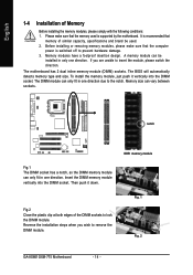
... when you are unable to insert the module, please switch the direction. Fig. 1 Fig. 2 GA-8S661GXM-775 Motherboard - 14 - Before installing or removing memory modules, please make sure that the memory used . 2. Memory modules have a foolproof insertion design. The BIOS will automatically detects memory type and size. notch Fig.1 The DIMM socket has a notch...
... when you are unable to insert the module, please switch the direction. Fig. 1 Fig. 2 GA-8S661GXM-775 Motherboard - 14 - Before installing or removing memory modules, please make sure that the memory used . 2. Memory modules have a foolproof insertion design. The BIOS will automatically detects memory type and size. notch Fig.1 The DIMM socket has a notch...
Manual
Page 15
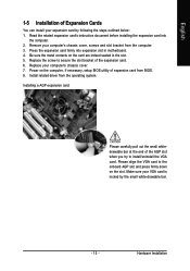
... your computer's chassis cover. 7. Power on the computer, if necessary, setup BIOS utility of Expansion Cards You can install your VGA card is locked by following the steps outlined below: 1. Replace your computer's chassis cover, screws and ...
... your computer's chassis cover. 7. Power on the computer, if necessary, setup BIOS utility of Expansion Cards You can install your VGA card is locked by following the steps outlined below: 1. Replace your computer's chassis cover, screws and ...
Manual
Page 20
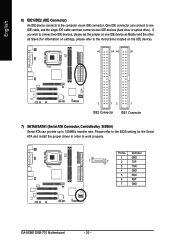
Please refer to the BIOS setting for information on settings, please refer to the instructions located on one IDE cable, and the single IDE cable can then connect to work ... via an IDE connector. English 6) IDE1/IDE2 (IDE Connector) An IDE device connects to 150MB/s transfer rate. Definition 1 GND 1 7 2 TXP 3 TXN 4 GND 5 RXN 6 RXP 7 GND GA-8S661GXM-775 Motherboard - 20 -
Please refer to the BIOS setting for information on settings, please refer to the instructions located on one IDE cable, and the single IDE cable can then connect to work ... via an IDE connector. English 6) IDE1/IDE2 (IDE Connector) An IDE device connects to 150MB/s transfer rate. Definition 1 GND 1 7 2 TXP 3 TXN 4 GND 5 RXN 6 RXP 7 GND GA-8S661GXM-775 Motherboard - 20 -
Manual
Page 25
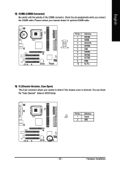
You can check the "Case Opened" status in BIOS Setup. Definition 1 1 Signal 2 GND - 25 - English 15) COMB (COMB Connector) Be careful with the polarity of the COMB connector. Please contact your nearest dealer for optional COMB cable. 1 2 9 10 Pin No. 1 2 3 4 5 6 7 8 9 10 Definition NDCDBNSINB NSOUTB NDTRBGND NDSRBNRTSBNCTSBNRIBNo Pin 16) CI (Chassis Intrusion, Case Open) This 2-pin connector allows your system to detect if the chassis cover is removed. Pin No. Hardware Installation Check the pin assignments while you connect the COMB cable.
You can check the "Case Opened" status in BIOS Setup. Definition 1 1 Signal 2 GND - 25 - English 15) COMB (COMB Connector) Be careful with the polarity of the COMB connector. Please contact your nearest dealer for optional COMB cable. 1 2 9 10 Pin No. 1 2 3 4 5 6 7 8 9 10 Definition NDCDBNSINB NSOUTB NDTRBGND NDSRBNRTSBNCTSBNRIBNo Pin 16) CI (Chassis Intrusion, Case Open) This 2-pin connector allows your system to detect if the chassis cover is removed. Pin No. Hardware Installation Check the pin assignments while you connect the COMB cable.

Manual
Page 29
... Input and Output System) includes a CMOS SETUP utility which allows user to configure required settings or to a new BIOS, either Gigabyte's Q-Flash or @BIOS utility can enter the BIOS setup screen by pressing "Ctrl + F1". If you to its original settings. Exit current page and return to select item ...The CMOS SETUP saves the configuration in the event that does not require users to boot to DOS before upgrading BIOS but directly download and update BIOS from BIOS default table Load the Optimized Defaults Q-Flash utility System Information Save all the CMOS changes, only for Main Menu ...
... Input and Output System) includes a CMOS SETUP utility which allows user to configure required settings or to a new BIOS, either Gigabyte's Q-Flash or @BIOS utility can enter the BIOS setup screen by pressing "Ctrl + F1". If you to its original settings. Exit current page and return to select item ...The CMOS SETUP saves the configuration in the event that does not require users to boot to DOS before upgrading BIOS but directly download and update BIOS from BIOS default table Load the Optimized Defaults Q-Flash utility System Information Save all the CMOS changes, only for Main Menu ...

Manual
Page 30
GA-8S661GXM-775 Motherboard - 30 - English The Main Menu (For example: BIOS Ver. : F1) Once you want, please press "Ctrl+F1" to access hidden advanced options. „ Standard CMOS Features This setup page includes all the items in standard compatible BIOS. „ Advanced BIOS... and fan, speed. „ MB Intelligent Tweaker (M.I .T). CMOS Setup Utility-Copyright (C) 1984-2005 Award Software ` Standard CMOS Features ` Advanced BIOS Features ` Integrated Peripherals ` Power Management Setup ` PnP/PCI Configurations ` PC Health Status ` MB Intelligent Tweaker (M.I .T.) This setup page is...
GA-8S661GXM-775 Motherboard - 30 - English The Main Menu (For example: BIOS Ver. : F1) Once you want, please press "Ctrl+F1" to access hidden advanced options. „ Standard CMOS Features This setup page includes all the items in standard compatible BIOS. „ Advanced BIOS... and fan, speed. „ MB Intelligent Tweaker (M.I .T). CMOS Setup Utility-Copyright (C) 1984-2005 Award Software ` Standard CMOS Features ` Advanced BIOS Features ` Integrated Peripherals ` Power Management Setup ` PnP/PCI Configurations ` PC Health Status ` MB Intelligent Tweaker (M.I .T.) This setup page is...
Manual
Page 31
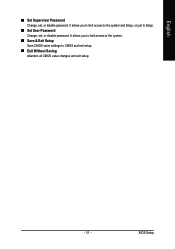
English „ Set Supervisor Password Change, set , or disable password. It allows you to limit access to the system. „ Save & Exit Setup Save CMOS value settings to Setup. „ Set User Password Change, set , or disable password. BIOS Setup It allows you to limit access to the system and Setup, or just to CMOS and exit setup. „ Exit Without Saving Abandon all CMOS value changes and exit setup. - 31 -
English „ Set Supervisor Password Change, set , or disable password. It allows you to limit access to the system. „ Save & Exit Setup Save CMOS value settings to Setup. „ Set User Password Change, set , or disable password. BIOS Setup It allows you to limit access to the system and Setup, or just to CMOS and exit setup. „ Exit Without Saving Abandon all CMOS value changes and exit setup. - 31 -
Manual
Page 32
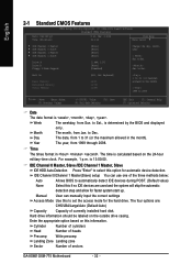
...) < Year> 1999 to 31 (or the maximum allowed in the month). is determined by the BIOS and displayed only. Day The date, from Jan. to Dec. Manual User can use one of sectors GA-8S661GXM-775 Motherboard - 32 - to select this information. Month The month, from 1 to 2098 KLJI: Move...Number of cylinders Head Precomp Number of heads Write precomp Landing Zone Landing zone Sector Number of the three methods below: Auto None Allows BIOS to automatically detect IDE devices during POST. (Default value) Select this to Sat., is 13:00:00. to set the access mode ...
...) < Year> 1999 to 31 (or the maximum allowed in the month). is determined by the BIOS and displayed only. Day The date, from Jan. to Dec. Manual User can use one of sectors GA-8S661GXM-775 Motherboard - 32 - to select this information. Month The month, from 1 to 2098 KLJI: Move...Number of cylinders Head Precomp Number of heads Write precomp Landing Zone Landing zone Sector Number of the three methods below: Auto None Allows BIOS to automatically detect IDE devices during POST. (Default value) Select this to Sat., is 13:00:00. to set the access mode ...


