Manual
Page 9
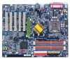
...; 4 Socket 775 CPU y Supports 533/800MHz FSB y L2 cache varies with CPU y GA-8IPE775 Series Motherboard: GA-8IPE775 Pro/GA-8IPE775-G/GA-8IPE775 y North Bridge: Intel® 865PE y South Bridge: Intel® ICH5 y 4 184-pin DDR DIMM sockets y Supports Dual channel DDR400/DDR333/DDR266 DIMM y Supports 128MB/256MB/512MB/1GB unbuffered DRAM y Supports up to 4GB DRAM (Max) (Note 1) y 1 AGP slot supports 8X/4X(1.5V) mode y 5 PCI slots y 2 IDE bus master (UDMA33/ATA66/ATA100) IDE ports for up to 4 ATAPI devices y Can connect up to 4 IDE devices y 1 Floppy port supports 2 FDD...
...; 4 Socket 775 CPU y Supports 533/800MHz FSB y L2 cache varies with CPU y GA-8IPE775 Series Motherboard: GA-8IPE775 Pro/GA-8IPE775-G/GA-8IPE775 y North Bridge: Intel® 865PE y South Bridge: Intel® ICH5 y 4 184-pin DDR DIMM sockets y Supports Dual channel DDR400/DDR333/DDR266 DIMM y Supports 128MB/256MB/512MB/1GB unbuffered DRAM y Supports up to 4GB DRAM (Max) (Note 1) y 1 AGP slot supports 8X/4X(1.5V) mode y 5 PCI slots y 2 IDE bus master (UDMA33/ATA66/ATA100) IDE ports for up to 4 ATAPI devices y Can connect up to 4 IDE devices y 1 Floppy port supports 2 FDD...
Manual
Page 10
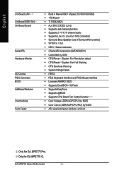
...-Board LAN On-Board IEEE1394 On-Board Sound Serial ATA Hardware Monitor I/O Control PS/2 Connector BIOS Additional Features Overclocking Form Factor y Build in Marvell 8001 Chipset (10/100/1000 Mbit) y 1 RJ45 port y Ti TSB43AB23 y ALC850 CODEC (UAJ) y Supports Jack Sensing function y Supports 2 / 4 / 6 / 8 channel audio y Supports Line In / Line Out / MIC connection y Surround Back Speaker (use of Surround-Kit to select) y SPDIF In / Out y CD In / Game connector y 2 Serial ATA connectors (SATA0/SATA1) y Controlled by ICH5 y CPU/Power /System Fan...
...-Board LAN On-Board IEEE1394 On-Board Sound Serial ATA Hardware Monitor I/O Control PS/2 Connector BIOS Additional Features Overclocking Form Factor y Build in Marvell 8001 Chipset (10/100/1000 Mbit) y 1 RJ45 port y Ti TSB43AB23 y ALC850 CODEC (UAJ) y Supports Jack Sensing function y Supports 2 / 4 / 6 / 8 channel audio y Supports Line In / Line Out / MIC connection y Surround Back Speaker (use of Surround-Kit to select) y SPDIF In / Out y CD In / Game connector y 2 Serial ATA connectors (SATA0/SATA1) y Controlled by ICH5 y CPU/Power /System Fan...
Manual
Page 15
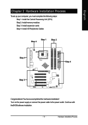
Hardware Installation Process Turn on the power supply or connect the power cable to the power outlet. Install the Central Processing Unit (CPU) Step 2- Continue with the BIOS/software installation. - 11 - You have accomplished the hardware installation! Install expansion cards Step 4- Install I/O Peripherals Cables Step 4 Step 1 Step 2 Step 4 Step 4 Step 3 Congratulations! Install memory modules Step 3- English Chapter 2 Hardware Installation Process To set up your computer, you must complete the following steps: Step 1-
Hardware Installation Process Turn on the power supply or connect the power cable to the power outlet. Install the Central Processing Unit (CPU) Step 2- Continue with the BIOS/software installation. - 11 - You have accomplished the hardware installation! Install expansion cards Step 4- Install I/O Peripherals Cables Step 4 Step 1 Step 2 Step 4 Step 4 Step 3 Congratulations! Install memory modules Step 3- English Chapter 2 Hardware Installation Process To set up your computer, you must complete the following steps: Step 1-
Manual
Page 17
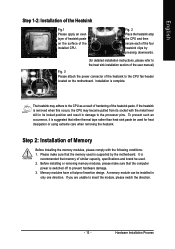
... sure that memory of similar capacity, specifications and brand be used for detailed installation instructions, please refer to the heat sink installation section of the user manual) Fig. 3 Please attach the power connector of the heatsink to insert the module, please switch the direction. - 13 - A memory module can be used . 2. English Step 1-2: Installation of the Heatsink Fig.1 Please apply an even layer of heatsink paste on the motherboard.
... sure that memory of similar capacity, specifications and brand be used for detailed installation instructions, please refer to the heat sink installation section of the user manual) Fig. 3 Please attach the power connector of the heatsink to insert the module, please switch the direction. - 13 - A memory module can be used . 2. English Step 1-2: Installation of the Heatsink Fig.1 Please apply an even layer of heatsink paste on the motherboard.
Manual
Page 22
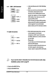
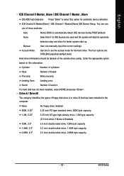
... not support USB controller, please contact OS vendor for GA-8IPE775 Pro. If you may connect speaker to Line Out jack, microphone to page 67. After install onboard audio driver, you want to page 24, and contact your device(s) such as USB keyboard,mouse, scanner, zip, speaker..etc. Only for optional SUR_CEN cable. Also make sure your nearest dealer for GA-8IPE775-G. can refer to enable 8-channel function you connect your device(s) into USB connector(s), please...
... not support USB controller, please contact OS vendor for GA-8IPE775 Pro. If you may connect speaker to Line Out jack, microphone to page 67. After install onboard audio driver, you want to page 24, and contact your device(s) such as USB keyboard,mouse, scanner, zip, speaker..etc. Only for optional SUR_CEN cable. Also make sure your nearest dealer for GA-8IPE775-G. can refer to enable 8-channel function you connect your device(s) into USB connector(s), please...
Manual
Page 25
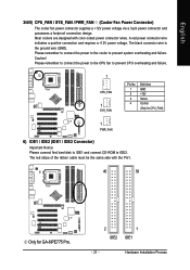
... cable must be the same side with color-coded power connector wires. Please remember to connect the power to the CPU fan to prevent CPU overheating and failure. 1 CPU_FAN 1 SYS_FAN Pin No. 1 2 3 4 Definition GND +12V Sense Control (Only for GA-8IPE775 Pro. 2 IDE2 1 IDE1 - 21 - Most coolers are designed with the Pin1. 40 39 Only for CPU_FAN) 1 PWR_FAN 6) IDE1 / IDE2 (IDE1 / IDE2 Connector) Important Notice: Please connect first hard disk...
... cable must be the same side with color-coded power connector wires. Please remember to connect the power to the CPU fan to prevent CPU overheating and failure. 1 CPU_FAN 1 SYS_FAN Pin No. 1 2 3 4 Definition GND +12V Sense Control (Only for GA-8IPE775 Pro. 2 IDE2 1 IDE1 - 21 - Most coolers are designed with the Pin1. 40 39 Only for CPU_FAN) 1 PWR_FAN 6) IDE1 / IDE2 (IDE1 / IDE2 Connector) Important Notice: Please connect first hard disk...
Manual
Page 35
... power is turned off, the battery on , pushing the button during the BIOS POST (Power-On Self Test) will take you to DOS before upgrading BIOS but directly download and update BIOS from BIOS default table Load the Optimized Defaults Dual BIOS /Q-Flash function System Information Save all the CMOS changes, only for Main Menu Only for GA-8IPE775 Pro. - 31 - Q-Flash allows the user to quickly and easily update or backup BIOS without entering the operating system. @BIOS is recommended that BIOS...
... power is turned off, the battery on , pushing the button during the BIOS POST (Power-On Self Test) will take you to DOS before upgrading BIOS but directly download and update BIOS from BIOS default table Load the Optimized Defaults Dual BIOS /Q-Flash function System Information Save all the CMOS changes, only for Main Menu Only for GA-8IPE775 Pro. - 31 - Q-Flash allows the user to quickly and easily update or backup BIOS without entering the operating system. @BIOS is recommended that BIOS...
Manual
Page 39
... options are used and the system will skip the automatic Manual detection step and allow for faster system start up. Drive A / Drive B The category identifies the types of floppy disk drive A or drive B that has been installed in the computer. IDE Channel 0 Master(Slave) / IDE Channel 1 Master(Slave) IDE Device Setup. BIOS Setup Enter the appropriate option based on the outside drive casing. English IDE Channel 0 Master, Slave / IDE Channel 1 Master, Slave IDE HDD Auto-Detection Press "Enter" to select this option for the hard drive...
... options are used and the system will skip the automatic Manual detection step and allow for faster system start up. Drive A / Drive B The category identifies the types of floppy disk drive A or drive B that has been installed in the computer. IDE Channel 0 Master(Slave) / IDE Channel 1 Master(Slave) IDE Device Setup. BIOS Setup Enter the appropriate option based on the outside drive casing. English IDE Channel 0 Master, Slave / IDE Channel 1 Master, Slave IDE HDD Auto-Detection Press "Enter" to select this option for the hard drive...
Manual
Page 45
... Enable onboard Serial port 1 and address is 3F8. (Default value) Enable onboard Serial port 1 and address is 2F8. 3E8/IRQ4 2E8/IRQ3 Enable onboard Serial port 1 and address is 2E8. BIOS Setup Only for GA-8IPE775-G. - 41 - Onboard H/W 1394 Enabled Enable onboard IEEE 1394 function.(Default value) Disabled Disable this function. Onboard H/W LAN Enabled Enable Onboard H/W LAN function. (Default value) Disabled Disable this function. Onboard LAN Boot ROM This function decide whether to invoke the boot ROM of the onboard LAN chip. Only for GA-8IPE775 Pro. Enable onboard...
... Enable onboard Serial port 1 and address is 3F8. (Default value) Enable onboard Serial port 1 and address is 2F8. 3E8/IRQ4 2E8/IRQ3 Enable onboard Serial port 1 and address is 2E8. BIOS Setup Only for GA-8IPE775-G. - 41 - Onboard H/W 1394 Enabled Enable onboard IEEE 1394 function.(Default value) Disabled Disable this function. Onboard H/W LAN Enabled Enable Onboard H/W LAN function. (Default value) Disabled Disable this function. Onboard LAN Boot ROM This function decide whether to invoke the boot ROM of the onboard LAN chip. Only for GA-8IPE775 Pro. Enable onboard...
Manual
Page 50
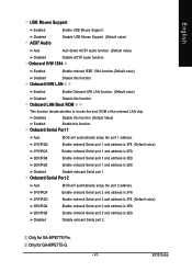
.... GA-8IPE775 Series Motherboard - 46 - English PC Health Status CMOS Setup Utility-Copyright (C) 1984-2004 Award Software PC Health Status Reset Case Open Status Case Opened Vcore DDR25V +3.3V +12V Current CPU Temperature Current CPU FAN Speed Current POWER FAN Speed 1 Current SYSTEM FAN Speed CPU Warning Temperature CPU FAN Fail Warning POWER FAN Fail Warning 1 SYSTEM FAN Fail Warning CPU Smart FAN Control 12 [Disabled] Yes OK OK OK OK 50oC 4687 RPM 0 RPM 0 RPM [Disabled] [Disabled] [Disabled] [Disabled] [Enabled] Item Help Menu Level` [Disabled] Don't monitor current fan speed [Enabled...
.... GA-8IPE775 Series Motherboard - 46 - English PC Health Status CMOS Setup Utility-Copyright (C) 1984-2004 Award Software PC Health Status Reset Case Open Status Case Opened Vcore DDR25V +3.3V +12V Current CPU Temperature Current CPU FAN Speed Current POWER FAN Speed 1 Current SYSTEM FAN Speed CPU Warning Temperature CPU FAN Fail Warning POWER FAN Fail Warning 1 SYSTEM FAN Fail Warning CPU Smart FAN Control 12 [Disabled] Yes OK OK OK OK 50oC 4687 RPM 0 RPM 0 RPM [Disabled] [Disabled] [Disabled] [Disabled] [Enabled] Item Help Menu Level` [Disabled] Don't monitor current fan speed [Enabled...
Manual
Page 54
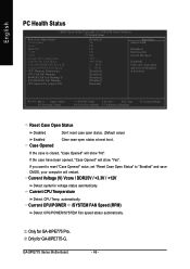
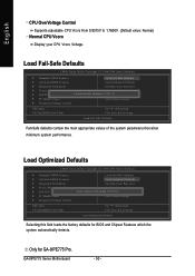
... your CPU Vcore Voltage. GA-8IPE775 Series Motherboard - 50 - Load Fail-Safe Defaults CMOS Setup Utility-Copyright (C) 1984-2004 Award Software ` Standard CMOS Features Load Fail-Safe Defaults ` Advanced BIOS Features Load Optimized Defaults ` Integrated Peripherals Set Supervisor Password ` Power Management Setup Set User Password ` PnP/PCI Configurations Load Fail-Safe Defaults (YS/aNv)e?&N Exit Setup ` PC Health Status Exit Without Saving ` Frequency/Voltage Control ESC: Quit F8: Dual BIOS 1/Q-Flash KLJI: Select Item F10: Save & Exit Setup Load Fail-Safe Defaults Fail-Safe...
... your CPU Vcore Voltage. GA-8IPE775 Series Motherboard - 50 - Load Fail-Safe Defaults CMOS Setup Utility-Copyright (C) 1984-2004 Award Software ` Standard CMOS Features Load Fail-Safe Defaults ` Advanced BIOS Features Load Optimized Defaults ` Integrated Peripherals Set Supervisor Password ` Power Management Setup Set User Password ` PnP/PCI Configurations Load Fail-Safe Defaults (YS/aNv)e?&N Exit Setup ` PC Health Status Exit Without Saving ` Frequency/Voltage Control ESC: Quit F8: Dual BIOS 1/Q-Flash KLJI: Select Item F10: Save & Exit Setup Load Fail-Safe Defaults Fail-Safe...
Manual
Page 55
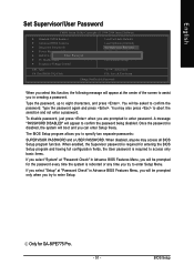
...Advance BIOS Features Menu, you will be asked to confirm the password being disabled. When disabled, anyone may also press to eight characters, and press . English Set Supervisor/User Password CMOS Setup Utility-Copyright (C) 1984-2004 Award Software ` Standard CMOS Features ` Advanced BIOS Features ` Integrated Peripherals ` Power Management Setup ` PnP/PCI ConfiguratioEnsnter Password: ` PC Health Status ` Frequency/Voltage Control Load Fail-Safe Defaults Load Optimized Defaults Set Supervisor Password Set User Password Save & Exit Setup Exit Without Saving ESC: Quit F8: Dual BIOS...
...Advance BIOS Features Menu, you will be asked to confirm the password being disabled. When disabled, anyone may also press to eight characters, and press . English Set Supervisor/User Password CMOS Setup Utility-Copyright (C) 1984-2004 Award Software ` Standard CMOS Features ` Advanced BIOS Features ` Integrated Peripherals ` Power Management Setup ` PnP/PCI ConfiguratioEnsnter Password: ` PC Health Status ` Frequency/Voltage Control Load Fail-Safe Defaults Load Optimized Defaults Set Supervisor Password Set User Password Save & Exit Setup Exit Without Saving ESC: Quit F8: Dual BIOS...
Manual
Page 56
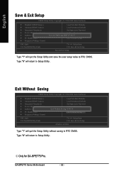
... will return to Setup Utility. Only for GA-8IPE775 Pro. GA-8IPE775 Series Motherboard - 52 - Type "N" will return to Setup Utility. English Save & Exit Setup CMOS Setup Utility-Copyright (C) 1984-2004 Award Software ` Standard CMOS Features ` Advanced BIOS Features ` Integrated Peripherals ` Power Management Setup ` PnP/PCI Configurations ` PC Health Status ` Frequency/Voltage Control ESC: Quit F8: Dual BIOS 1/Q-Flash Load Fail-Safe Defaults Load Optimized Defaults Set Supervisor Password Set User Password Save to CMOS and EXITSa(Yve/N&)?EYxit Setup Exit Without Saving KLJI: Select...
... will return to Setup Utility. Only for GA-8IPE775 Pro. GA-8IPE775 Series Motherboard - 52 - Type "N" will return to Setup Utility. English Save & Exit Setup CMOS Setup Utility-Copyright (C) 1984-2004 Award Software ` Standard CMOS Features ` Advanced BIOS Features ` Integrated Peripherals ` Power Management Setup ` PnP/PCI Configurations ` PC Health Status ` Frequency/Voltage Control ESC: Quit F8: Dual BIOS 1/Q-Flash Load Fail-Safe Defaults Load Optimized Defaults Set Supervisor Password Set User Password Save to CMOS and EXITSa(Yve/N&)?EYxit Setup Exit Without Saving KLJI: Select...
Manual
Page 62
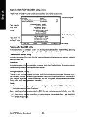
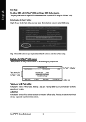
... tasks. Dual BIOS Utility Boot From Main Bios Main ROM Type/Size SST 49LF003A Backup ROM Type/Size SST 49LF003A Dual BIOS utility bar 512K 512K Task menu for Dual BIOS utility Task menu for Q-FlashTM utility Enter : Run Wide Range Protection Disable Boot From Main Bios Auto Recovery Enable Halt On Error Disable Copy Main ROM Data to Backup Load Default Settings Save Settings to Floppy KL:Move ESC:Reset F10:Power Off Q-FlashTM utility title bar Action bar Task menu for Q-Flash utility: Contains the names of the following key components. Press arrow buttons on...
... tasks. Dual BIOS Utility Boot From Main Bios Main ROM Type/Size SST 49LF003A Backup ROM Type/Size SST 49LF003A Dual BIOS utility bar 512K 512K Task menu for Dual BIOS utility Task menu for Q-FlashTM utility Enter : Run Wide Range Protection Disable Boot From Main Bios Auto Recovery Enable Halt On Error Disable Copy Main ROM Data to Backup Load Default Settings Save Settings to Floppy KL:Move ESC:Reset F10:Power Off Q-FlashTM utility title bar Action bar Task menu for Q-Flash utility: Contains the names of the following key components. Press arrow buttons on...
Manual
Page 63
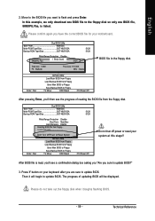
...update BIOS. After BIOS file is listed. Please do not take out the floppy disk when it will be displayed. Then it begins flashing BIOS. - 59 - Dual BIOS Utility Boot From Main Bios Main ROM Type/Size SST 49LF003A Backup ROM Type/Size SST 49LF003A 512K 512K Wide Range Protection Disable 8KNXPU.Fba Bo1ot fFilreo(ms) foMunadin Bios Auto Recovery Enable 512K Halt On Error Disable Total size: 1.39MCopy Main ROM Data tForeBeacskizuep: 911.50K F5 : Refresh Load Default Settings DEL : Delete Save Settings to CMOS Enter : Run Q-Flash Utility Load Main BIOS from Floppy Load...
...update BIOS. After BIOS file is listed. Please do not take out the floppy disk when it will be displayed. Then it begins flashing BIOS. - 59 - Dual BIOS Utility Boot From Main Bios Main ROM Type/Size SST 49LF003A Backup ROM Type/Size SST 49LF003A 512K 512K Wide Range Protection Disable 8KNXPU.Fba Bo1ot fFilreo(ms) foMunadin Bios Auto Recovery Enable 512K Halt On Error Disable Total size: 1.39MCopy Main ROM Data tForeBeacskizuep: 911.50K F5 : Refresh Load Default Settings DEL : Delete Save Settings to CMOS Enter : Run Q-Flash Utility Load Main BIOS from Floppy Load...
Manual
Page 66
... Load Fail-Safe Defaults ` Integrated Peripherals Load Optimized Defaults ` Power Management Setup Set Supervisor Password ` PnP/PCI ConfiguratEionntesr Q-Flash Utility S(Yet/NU)s?eYr Password ` PC Health Status Save & Exit Setup ` Frequency/Voltage Control Exit Without Saving ESC: Quit F8: Q-Flash KLJI: Select Item F10: Save & Exit Setup Step 2: Press F8 button on your keyboard to Floppy Enter : Run KL:Move ESC:Reset 256K F10:Power Off Q-FlashTM utility bar Action bar Task menu for Q-FlashTM utility Q-Flash Utility V1.30 Flash Type/Size...
... Load Fail-Safe Defaults ` Integrated Peripherals Load Optimized Defaults ` Power Management Setup Set Supervisor Password ` PnP/PCI ConfiguratEionntesr Q-Flash Utility S(Yet/NU)s?eYr Password ` PC Health Status Save & Exit Setup ` Frequency/Voltage Control Exit Without Saving ESC: Quit F8: Q-Flash KLJI: Select Item F10: Save & Exit Setup Step 2: Press F8 button on your keyboard to Floppy Enter : Run KL:Move ESC:Reset 256K F10:Power Off Q-FlashTM utility bar Action bar Task menu for Q-FlashTM utility Q-Flash Utility V1.30 Flash Type/Size...
Manual
Page 79
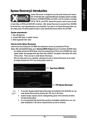
... hard disks on . . . Award Modular BIOS v6.00PG, An Energy Star Ally Copyright (C) 1984-2004, Award Software, Inc. VESA-supported VGA cards How to use the Xpress Recovery2 Initial access by pressing the F9 key: Steps: After entering BIOS Setup, go to Advanced BIOS Feature and set to enter Xpress Recovery2 without the CD-ROM. Technical Reference If you wish to run Xpress Recovery2 later, you can be immediately installed...
... hard disks on . . . Award Modular BIOS v6.00PG, An Energy Star Ally Copyright (C) 1984-2004, Award Software, Inc. VESA-supported VGA cards How to use the Xpress Recovery2 Initial access by pressing the F9 key: Steps: After entering BIOS Setup, go to Advanced BIOS Feature and set to enter Xpress Recovery2 without the CD-ROM. Technical Reference If you wish to run Xpress Recovery2 later, you can be immediately installed...
Manual
Page 84
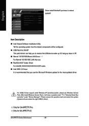
... audio. „ Intel USB 2.0 Driver It is recommended that you use Windows Service Pack. you to reboot system!! Only for GA-8IPE775-G. GA-8IPE775 Series Motherboard - 80 - English Driver install finished!! Item Description „ Intel Chipset Software Installation Utility Tell the operating system how the chipset components will be configured. „ USB Patch for WinXP This patch driver can help you have to resolve the USB device wake up S3 hang up issue in "Universal Serial Bus controller...
... audio. „ Intel USB 2.0 Driver It is recommended that you use Windows Service Pack. you to reboot system!! Only for GA-8IPE775-G. GA-8IPE775 Series Motherboard - 80 - English Driver install finished!! Item Description „ Intel Chipset Software Installation Utility Tell the operating system how the chipset components will be configured. „ USB Patch for WinXP This patch driver can help you have to resolve the USB device wake up S3 hang up issue in "Universal Serial Bus controller...
Manual
Page 87
... setting manually to disable the onboard VGA. - 83 - Take out the battery gently and put it is still on power. 6. Answer: Please remember to clear CMOS. Answer: Please make sure the speaker you can take off power. 2. Question 6: How do I clear CMOS? Answer: In some options that 's why the light is plugged in, so you can use a metal object to change another speaker with an internal amplifier. If your board has a Clear CMOS jumper...
... setting manually to disable the onboard VGA. - 83 - Take out the battery gently and put it is still on power. 6. Answer: Please remember to clear CMOS. Answer: Please make sure the speaker you can take off power. 2. Question 6: How do I clear CMOS? Answer: In some options that 's why the light is plugged in, so you can use a metal object to change another speaker with an internal amplifier. If your board has a Clear CMOS jumper...
Manual
Page 88
... or display card error 1 long 3 short: Keyboard error 1 long 9 short: BIOS ROM error Continuous long beeps: DRAM error Continuous short beeps: Power error GA-8IPE775 Series Motherboard - 84 - AMI BIOS Beep Codes *Computer gives 1 short beep when system boots successfully. *Except for beep code 8, these beeps usually stand for reference purposes. If the cable is not provided with the motherboard package to the USB Over Current pin in the Front USB Panel. Answer: The beep codes below may help you have connected any cable that is your own cables to case. Question 8: Sometimes I use...
... or display card error 1 long 3 short: Keyboard error 1 long 9 short: BIOS ROM error Continuous long beeps: DRAM error Continuous short beeps: Power error GA-8IPE775 Series Motherboard - 84 - AMI BIOS Beep Codes *Computer gives 1 short beep when system boots successfully. *Except for beep code 8, these beeps usually stand for reference purposes. If the cable is not provided with the motherboard package to the USB Over Current pin in the Front USB Panel. Answer: The beep codes below may help you have connected any cable that is your own cables to case. Question 8: Sometimes I use...


