Manual
Page 5
Chapter 3 Install Drivers 51 3-1 Install Chipset Drivers 51 3-2 Software Applications 52 3-3 Driver CD Information 52 3-4 Hardware Information 53 3-5 Contact Us ...53 Chapter 4 Appendix 55 4-1 Unique Software Utilities 55 4-1-1 Xpress Recovery Introduction 55 4-1-2 Flash BIOS Method Introduction 58 4-1-3 2 / 4 / 6 / 8 Channel Audio Function Introduction 67 4-1-4 Jack-Sensing and UAJ Introduction 73 4-2 Troubleshooting 75 - 5 -
Chapter 3 Install Drivers 51 3-1 Install Chipset Drivers 51 3-2 Software Applications 52 3-3 Driver CD Information 52 3-4 Hardware Information 53 3-5 Contact Us ...53 Chapter 4 Appendix 55 4-1 Unique Software Utilities 55 4-1-1 Xpress Recovery Introduction 55 4-1-2 Flash BIOS Method Introduction 58 4-1-3 2 / 4 / 6 / 8 Channel Audio Function Introduction 67 4-1-4 Jack-Sensing and UAJ Introduction 73 4-2 Troubleshooting 75 - 5 -
Manual
Page 6
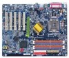
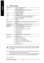
GA-8IP775(-G) Motherboard Layout KB_MS CPU_FAN ATX_12V COMA FDD ATX COMB LPT R_USB LGA775 IDE1 IDE2 GA-8IP775(-G) DDR1 DDR2 USB LAN (*) AUDIO CD_IN Intel® 865P Marvell F_AUDIO 8001 (*) AGP DDR4 DDR3 IT8712 CODEC SUR_CEN DUAL CHANNEL DDR PCI1 SATA P4 Titan PCI2 CI IR_CIR PCI3 PCI4 BIOS PCI5 GAME SPDIF_IO ICH5 SATA1 SATA0 BAT CLR_CMOS SYS_FAN INFO_LINK F_PANEL F_USB2 PWR_LED F_USB1 (*) Only for GA-8IP775-G. - 6 -
GA-8IP775(-G) Motherboard Layout KB_MS CPU_FAN ATX_12V COMA FDD ATX COMB LPT R_USB LGA775 IDE1 IDE2 GA-8IP775(-G) DDR1 DDR2 USB LAN (*) AUDIO CD_IN Intel® 865P Marvell F_AUDIO 8001 (*) AGP DDR4 DDR3 IT8712 CODEC SUR_CEN DUAL CHANNEL DDR PCI1 SATA P4 Titan PCI2 CI IR_CIR PCI3 PCI4 BIOS PCI5 GAME SPDIF_IO ICH5 SATA1 SATA0 BAT CLR_CMOS SYS_FAN INFO_LINK F_PANEL F_USB2 PWR_LED F_USB1 (*) Only for GA-8IP775-G. - 6 -
Manual
Page 10
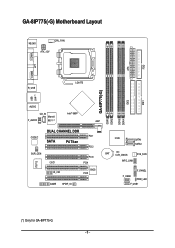
... memory module. English 1-2 Feature Summary M otherboard CPU Chip set Mem ory Slo ts IDE Connections FDD Connections Onboard SATA Peripherals Onboard LAN (*) Onboard Audio w GA-8IP775 Series Motherboard: GA-8IP 775-G/GA-8 IP775 w Supports the latest Intel® Pentium® 4 LGA775 CPU w Supports 800/533MHz FSB w L2 cache varies with CPU w Northbridge: Intel® 865P...
... memory module. English 1-2 Feature Summary M otherboard CPU Chip set Mem ory Slo ts IDE Connections FDD Connections Onboard SATA Peripherals Onboard LAN (*) Onboard Audio w GA-8IP775 Series Motherboard: GA-8IP 775-G/GA-8 IP775 w Supports the latest Intel® Pentium® 4 LGA775 CPU w Supports 800/533MHz FSB w L2 cache varies with CPU w Northbridge: Intel® 865P...
Manual
Page 17
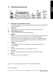
...(s), please make sure your OS does not support USB controller, please contact OS vendor for GA-8IP775-G. - 17 - can be connected to this connector. Line In Devices like CD-ROM, walkman etc. You can use audio software to the lower port (purple). Also make sure your OS or device(s)vendors. If... your OS supports USB controller. Line Out Connect the stereo speakers, earphone or front surround channels to Line In jack. channel audio functioning. (*) Only for possible patch or driver upgrade. Para llel Port The parallel port allows connection of 10/100/1000Mbps.
...(s), please make sure your OS does not support USB controller, please contact OS vendor for GA-8IP775-G. - 17 - can be connected to this connector. Line In Devices like CD-ROM, walkman etc. You can use audio software to the lower port (purple). Also make sure your OS or device(s)vendors. If... your OS supports USB controller. Line Out Connect the stereo speakers, earphone or front surround channels to Line In jack. channel audio functioning. (*) Only for possible patch or driver upgrade. Para llel Port The parallel port allows connection of 10/100/1000Mbps.

Manual
Page 23
... note, you must have the alternative of using front audio connector or of using rear audio connector to use Front Audio connector, you can have front audio connector. To find out if the chassis you are buying support front audio connector, please contact your nearest dealer for optional SUR_CEN ... 8 Pin No. 1 2 3 4 5 6 7 8 Definition SUROUT L SUROUT R GND No Pin CENTER_OUT BASS_OUT AUX_L AUX_R - 23 - In order to utilize the front audio header, your chassis must remove 5-6, 9-10 Jumper. Also please make sure the pin assigment on the cable is the same as the pin assigment on...
... note, you must have the alternative of using front audio connector or of using rear audio connector to use Front Audio connector, you can have front audio connector. To find out if the chassis you are buying support front audio connector, please contact your nearest dealer for optional SUR_CEN ... 8 Pin No. 1 2 3 4 5 6 7 8 Definition SUROUT L SUROUT R GND No Pin CENTER_OUT BASS_OUT AUX_L AUX_R - 23 - In order to utilize the front audio header, your chassis must remove 5-6, 9-10 Jumper. Also please make sure the pin assigment on the cable is the same as the pin assigment on...
Manual
Page 24
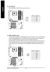
... dealer. 26 15 Pin No. 1 2 3 4 5 6 Definition VCC No Pin SPDIF SPDIFI GND GND GA-8IP775 Series Motherboard - 24 - For optional SPDIF_IO cable, please contact your stereo system has digital input function. Be careful with the polarity of providing digital audio to external speakers or compressed AC3 data to an external Dolby Digital Decoder.... Pin No. Use SPDIF IN feature only when your device has digital output function. English 12) CD_IN (CD IN) Connect CD-ROM or DVD-ROM audio out to work or even damage it.
... dealer. 26 15 Pin No. 1 2 3 4 5 6 Definition VCC No Pin SPDIF SPDIFI GND GND GA-8IP775 Series Motherboard - 24 - For optional SPDIF_IO cable, please contact your stereo system has digital input function. Be careful with the polarity of providing digital audio to external speakers or compressed AC3 data to an external Dolby Digital Decoder.... Pin No. Use SPDIF IN feature only when your device has digital output function. English 12) CD_IN (CD IN) Connect CD-ROM or DVD-ROM audio out to work or even damage it.
Manual
Page 26
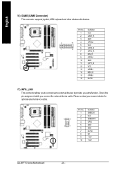
...) GAME (GAME Connector) This connector supports joystick, MIDI keyboard and other relate audio devices. Please contact your nearest dealer for optional external device cable. 10 9 2 1 Pin No. 1 2 3 4 5 6 7 8 9 10 Definition SMBCLK VCC SMBDATA GPIO GND GND No Pin NC +12V +12V GA-8IP775 Series Motherboard - 26 - Pin No. Definition 1 VCC 2 GRX1_R 3 GND 2 16 4 GPSA2...
...) GAME (GAME Connector) This connector supports joystick, MIDI keyboard and other relate audio devices. Please contact your nearest dealer for optional external device cable. 10 9 2 1 Pin No. 1 2 3 4 5 6 7 8 9 10 Definition SMBCLK VCC SMBDATA GPIO GND GND No Pin NC +12V +12V GA-8IP775 Series Motherboard - 26 - Pin No. Definition 1 VCC 2 GRX1_R 3 GND 2 16 4 GPSA2...
Manual
Page 36
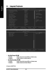
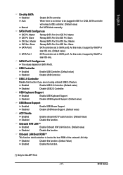
...PCI IDE On-Chip SATA x SATA Port0 Configure as SATA Port1 Configure as USB Controller USB 2.0 Controller USB Keyboard Support USB Mouse Support AC97 Audio Onboard H/W LAN (*) Onboard LAN Boot ROM (*) Onboard Serial Port 1 Onboard Serial Port 2 UART Mode Select x UR2 Duplex Mode Onboard ...General Help On-Chip Primary PCI IDE Enabled Enable onboard 1st channel IDE port. (Default value) Disabled Disable onboard 1st channel IDE port. GA-8IP775 Series Motherboard - 36 - On-Chip Secondary PCI IDE Enabled Enable onboard 2nd channel IDE port. (Default value) Disabled Disable onboard 2nd ...
...PCI IDE On-Chip SATA x SATA Port0 Configure as SATA Port1 Configure as USB Controller USB 2.0 Controller USB Keyboard Support USB Mouse Support AC97 Audio Onboard H/W LAN (*) Onboard LAN Boot ROM (*) Onboard Serial Port 1 Onboard Serial Port 2 UART Mode Select x UR2 Duplex Mode Onboard ...General Help On-Chip Primary PCI IDE Enabled Enable onboard 1st channel IDE port. (Default value) Disabled Disable onboard 1st channel IDE port. GA-8IP775 Series Motherboard - 36 - On-Chip Secondary PCI IDE Enabled Enable onboard 2nd channel IDE port. (Default value) Disabled Disable onboard 2nd ...
Manual
Page 37
...onboard LAN chip. Slave. Onboard H/W LAN (*) Enabled Enable Onboard H/W LAN function. (Default value) Disabled Disable this function. (*) Only for GA-8IP775-G. - 37 - English On-chip SATA Disabled Disable SATA controller. USB Keyboard Support Enabled Enable USB Keyboard Support. Onboard LAN Boot ROM (*)...Sec. IDE Sec. USB 2.0 Controller Disable this function. Disabled Disable USB Mouse Support. (Default value) AC97 Audio Enabled Enable onboard AC'97 audio function. (Default Value) Disabled Disable this function if you are not using onboard USB 2.0 feature.
...onboard LAN chip. Slave. Onboard H/W LAN (*) Enabled Enable Onboard H/W LAN function. (Default value) Disabled Disable this function. (*) Only for GA-8IP775-G. - 37 - English On-chip SATA Disabled Disable SATA controller. USB Keyboard Support Enabled Enable USB Keyboard Support. Onboard LAN Boot ROM (*)...Sec. IDE Sec. USB 2.0 Controller Disable this function. Disabled Disable USB Mouse Support. (Default value) AC97 Audio Enabled Enable onboard AC'97 audio function. (Default Value) Disabled Disable this function if you are not using onboard USB 2.0 feature.
Manual
Page 67
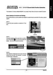
... of windows 98SE/2K/ME/XP is applied. Click the icon to install the function! STEP 1: Connect the stereo speakers or earphone to complete 2 channel audio configuration. - 67 - Line Out STEP 3: Click "Speaker Configuration" then click on the lower right hand taskbar. English 4-1-3 2 / 4 / 6 / 8 Channel...
... of windows 98SE/2K/ME/XP is applied. Click the icon to install the function! STEP 1: Connect the stereo speakers or earphone to complete 2 channel audio configuration. - 67 - Line Out STEP 3: Click "Speaker Configuration" then click on the lower right hand taskbar. English 4-1-3 2 / 4 / 6 / 8 Channel...

Manual
Page 68
Then click on the lower right hand taskbar. English 4 Channel Analog Audio Output Mode STEP 1 : Connect the front channels to "Line Out", the rear channels to select the function. Line Out Line In STEP 3 : Click "Speaker Configuration" and select the "UAJ Function". GA-8IP775 Series Motherboard - 68 - Click the icon to "Line In". STEP 2 : Following installation of the audio driver, you find a icon a Sound Effect icon on the left selection bar and select "4CH Speaker" to complete 4 channel audio configuration.
Then click on the lower right hand taskbar. English 4 Channel Analog Audio Output Mode STEP 1 : Connect the front channels to "Line Out", the rear channels to select the function. Line Out Line In STEP 3 : Click "Speaker Configuration" and select the "UAJ Function". GA-8IP775 Series Motherboard - 68 - Click the icon to "Line In". STEP 2 : Following installation of the audio driver, you find a icon a Sound Effect icon on the left selection bar and select "4CH Speaker" to complete 4 channel audio configuration.
Manual
Page 69
... rear channels to "Line In", and the Center/Subwoofer channels to complete 6 channel audio configuration. - 69 - English 6 Channel Analog Audio Output Mode Use the back audio panel to select the function. MIC In Line Out STEP 2 : Following installation of the audio driver, you find a icon a Sound Effect icon on the left selection bar and...
... rear channels to "Line In", and the Center/Subwoofer channels to complete 6 channel audio configuration. - 69 - English 6 Channel Analog Audio Output Mode Use the back audio panel to select the function. MIC In Line Out STEP 2 : Following installation of the audio driver, you find a icon a Sound Effect icon on the left selection bar and...

Manual
Page 70
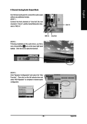
...Surround-Kit "SUB CENTER" and the R/L channels to the "LINE OUT" port located on the motherboard. GA-8IP775 Series Motherboard - 70 - English 8 Channel Audio Setup (using Audio Combo Kit, Optional Device): (Audio Combo Kit offers SPDIF output, an optical and coaxial cable and a Surround-Kit. STEP 2 : Connect... the Surround-Kit to the SUR_CEN connector located on the audio panel and the rear channels to the Surround-Kit "REAR R/L" port. The Surround-Kit offers R/L surround, center/subwoofer output and rear surround) STEP 1 : Secure the Audio Combo Kit at the panel on the back of 8 channel...
...Surround-Kit "SUB CENTER" and the R/L channels to the "LINE OUT" port located on the motherboard. GA-8IP775 Series Motherboard - 70 - English 8 Channel Audio Setup (using Audio Combo Kit, Optional Device): (Audio Combo Kit offers SPDIF output, an optical and coaxial cable and a Surround-Kit. STEP 2 : Connect... the Surround-Kit to the SUR_CEN connector located on the audio panel and the rear channels to the Surround-Kit "REAR R/L" port. The Surround-Kit offers R/L surround, center/subwoofer output and rear surround) STEP 1 : Secure the Audio Combo Kit at the panel on the back of 8 channel...

Manual
Page 71
..., you find a icon a Sound Effect icon on the left selection bar and select "8CH Speaker" to complete 8 channel audio configuration. Appendix English Click the icon to the "LINE IN" port. STEP 5 : Click "Speaker Configuration" and select both the "UAJ Function" and "Only ...Surround-Kit". Method 2: Connect the front channels to the "LINE OUT" port located on the audio panel and the rear channels to select the function. Sound Effect Configuration: At the sound effect menu, users can adjust sound option settings as desired...
..., you find a icon a Sound Effect icon on the left selection bar and select "8CH Speaker" to complete 8 channel audio configuration. Appendix English Click the icon to the "LINE IN" port. STEP 5 : Click "Speaker Configuration" and select both the "UAJ Function" and "Only ...Surround-Kit". Method 2: Connect the front channels to the "LINE OUT" port located on the audio panel and the rear channels to select the function. Sound Effect Configuration: At the sound effect menu, users can adjust sound option settings as desired...
Manual
Page 73
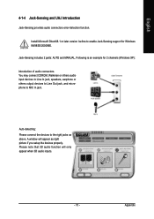
...Sensing includes 2 parts: AUTO and MANUAL. Appendix English 4-1-4 Jack-Sensing and UAJ Introduction Jack-Sensing provides audio connectors error-detection function. A window will only appear when 3D audio inputs. - 73 - Install Microsoft DirectX8.1 or later version before to enable Jack-Sensing support for 2 ...channels (Windows XP): Introduction of audio connectors You may connect CDROM, Walkman or others audio input devices to Line In jack, speakers, earphone or others output devices to Line Out jack, and ...
...Sensing includes 2 parts: AUTO and MANUAL. Appendix English 4-1-4 Jack-Sensing and UAJ Introduction Jack-Sensing provides audio connectors error-detection function. A window will only appear when 3D audio inputs. - 73 - Install Microsoft DirectX8.1 or later version before to enable Jack-Sensing support for 2 ...channels (Windows XP): Introduction of audio connectors You may connect CDROM, Walkman or others audio input devices to Line In jack, speakers, earphone or others output devices to Line Out jack, and ...

Manual
Page 74
GA-8IP775 Series Motherboard - 74 - Enable UAJ function: You can click "UAJ Automatic" button to enable UAJ function. UAJ Introduction UAJ (Universal Audio Jack) has a very smart feature: It will switch signal automatically when user plugs his audio device to the wrong jack (Line-in or Line-out jack, the device will ...come out as right picture. That means users do not need to worry the audio device should be plug in Line-in / Line-out). English If you set, please press "Manual Selection" to set wrong with the connectors,...
GA-8IP775 Series Motherboard - 74 - Enable UAJ function: You can click "UAJ Automatic" button to enable UAJ function. UAJ Introduction UAJ (Universal Audio Jack) has a very smart feature: It will switch signal automatically when user plugs his audio device to the wrong jack (Line-in or Line-out jack, the device will ...come out as right picture. That means users do not need to worry the audio device should be plug in Line-in / Line-out). English If you set, please press "Manual Selection" to set wrong with the connectors,...


