
User Manual
Page 6
... 5 Features Summary 5 GA-8IG1000MK Motherboard Layout 7 Block Diagram 8 Chapter 2 Hardware Installation Process 11 Step 1: Install the Central Processing Unit (CPU 12 Step 1-1: CPU Installation 12 Step 1-2: CPU Cooling Fan Installation 13 Step 2: Install Memory Modules 14 Step 3: Install expansion cards 16 Step 4: Connect ribbon cables, cabinet wires and power supply 17 Step 4-1: I/O Back Panel Introduction 17 Step 4-2: Connectors Introduction 19 Chapter 3 BIOS Setup 33 The Main Menu (For example: BIOS Ver. : E16 34 Standard CMOS Features 36 Advanced BIOS Features 39...
... 5 Features Summary 5 GA-8IG1000MK Motherboard Layout 7 Block Diagram 8 Chapter 2 Hardware Installation Process 11 Step 1: Install the Central Processing Unit (CPU 12 Step 1-1: CPU Installation 12 Step 1-2: CPU Cooling Fan Installation 13 Step 2: Install Memory Modules 14 Step 3: Install expansion cards 16 Step 4: Connect ribbon cables, cabinet wires and power supply 17 Step 4-1: I/O Back Panel Introduction 17 Step 4-2: Connectors Introduction 19 Chapter 3 BIOS Setup 33 The Main Menu (For example: BIOS Ver. : E16 34 Standard CMOS Features 36 Advanced BIOS Features 39...

User Manual
Page 9
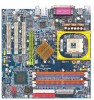
.../ATA100) operation modes y Can connect up to 4 IDE devices y 2 Serial ATA connectors in 150 MB/s operation mode y Controlled by ICH5 y 1 Floppy port supports 2 FDD with 360K, 720K,1.2M, 1.44M and 2.88M bytes y 1 Parallel port supports Normal/EPP/ECP mode y 1 Serial port (COMA), 1 VGA port, COMB on board y 8 USB 2.0/1.1 ports (4 x Rear, 4 x Front by cable) y 1 IrDA connector for system usage and therefore the actual memory size is only supported when using FSB 800 Pentium 4 processor. Introduction Due to chipset (Intel 865G...
.../ATA100) operation modes y Can connect up to 4 IDE devices y 2 Serial ATA connectors in 150 MB/s operation mode y Controlled by ICH5 y 1 Floppy port supports 2 FDD with 360K, 720K,1.2M, 1.44M and 2.88M bytes y 1 Parallel port supports Normal/EPP/ECP mode y 1 Serial port (COMA), 1 VGA port, COMB on board y 8 USB 2.0/1.1 ports (4 x Rear, 4 x Front by cable) y 1 IrDA connector for system usage and therefore the actual memory size is only supported when using FSB 800 Pentium 4 processor. Introduction Due to chipset (Intel 865G...
User Manual
Page 10
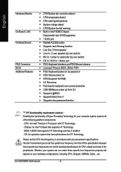
... specific bus frequencies properly will depend on y STR (Suspend-To-RAM) y AC Recovery y Poly fuse for keyboard over-current protection y USB KB/Mouse wake up from S3 y Supports @BIOS y Supports EasyTune 4 y Supports clear password function "*" HT functionality requirement content : Enabling the functionality of Hyper-Threading Technology for your computer system requires all of the peripherals. English Hardware Monitor On-Board LAN On-Board Sound PS/2 Connector BIOS Additional Features y CPU/System fan revolution detect y CPU temperature detect y CPU...
... specific bus frequencies properly will depend on y STR (Suspend-To-RAM) y AC Recovery y Poly fuse for keyboard over-current protection y USB KB/Mouse wake up from S3 y Supports @BIOS y Supports EasyTune 4 y Supports clear password function "*" HT functionality requirement content : Enabling the functionality of Hyper-Threading Technology for your computer system requires all of the peripherals. English Hardware Monitor On-Board LAN On-Board Sound PS/2 Connector BIOS Additional Features y CPU/System fan revolution detect y CPU temperature detect y CPU...
User Manual
Page 15
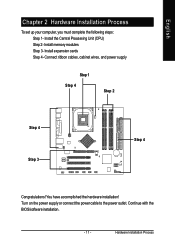
Install memory modules Step 3- Turn on the power supply or connect the power cable to the power outlet. You have accomplished the hardware installation! Connect ribbon cables, cabinet wires, and power supply Step 1 Step 4 Step 2 Step 4 Step 3 Step 4 Congratulations! Continue with the BIOS/software installation. - 11 - Install expansion cards Step 4- Hardware Installation Process Install the Central Processing Unit (CPU) Step 2- English Chapter 2 Hardware Installation Process To set up your computer, you must complete the following steps: Step 1-
Install memory modules Step 3- Turn on the power supply or connect the power cable to the power outlet. You have accomplished the hardware installation! Connect ribbon cables, cabinet wires, and power supply Step 1 Step 4 Step 2 Step 4 Step 3 Step 4 Congratulations! Continue with the BIOS/software installation. - 11 - Install expansion cards Step 4- Hardware Installation Process Install the Central Processing Unit (CPU) Step 2- English Chapter 2 Hardware Installation Process To set up your computer, you must complete the following steps: Step 1-
User Manual
Page 20
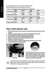
... expansion card. 6. Press the expansion card firmly into the computer. 2. drawable bar. GA-8IG1000MK Motherboard - 16 - Read the related expansion card's instruction document before install the expansion card into expansion slot in the slot. 5. When an AGP 2X (3.3V) card is installed the 2X_DET will not boot up , indicating a non-supported graphics card is inserted. Replace your computer's chassis cover, screws and slot bracket from the operating system. Install related driver from...
... expansion card. 6. Press the expansion card firmly into the computer. 2. drawable bar. GA-8IG1000MK Motherboard - 16 - Read the related expansion card's instruction document before install the expansion card into expansion slot in the slot. 5. When an AGP 2X (3.3V) card is installed the 2X_DET will not boot up , indicating a non-supported graphics card is inserted. Replace your computer's chassis cover, screws and slot bracket from the operating system. Install related driver from...

User Manual
Page 22
... Out" Connect "Rear Speaker" to "Line In" Connect "Center and Subwoofer" to Serial ports. GA-8IG1000MK Motherboard - 18 - If you want the detail information for hardware connection. English Z Parallel Port, Serial Port and VGA port (LPT / COMA / VGA) Parallel Port (25 pin Female) This connector supports 1 standard COM port , 1 Parallel port and 1 VGA port. mouse and modem etc. If you have 2 choose for 2-/4-/6-channel audio setup installation, please refer to enable 6-channel function, you want to page 67. Device like...
... Out" Connect "Rear Speaker" to "Line In" Connect "Center and Subwoofer" to Serial ports. GA-8IG1000MK Motherboard - 18 - If you want the detail information for hardware connection. English Z Parallel Port, Serial Port and VGA port (LPT / COMA / VGA) Parallel Port (25 pin Female) This connector supports 1 standard COM port , 1 Parallel port and 1 VGA port. mouse and modem etc. If you have 2 choose for 2-/4-/6-channel audio setup installation, please refer to enable 6-channel function, you want to page 67. Device like...

User Manual
Page 41
... SECTORS Number of floppy disk drive A or drive B that has been installed in . Note that the specifications of hard disk from drive C to the following items. Enter the information directly from the keyboard and press . CYLS. BIOS Setup There are two types: auto type, and manual type. Auto type which will be provided in the computer. The hard disk will not work properly if you select User Type, related information will automatically detect HDD type. English Time...
... SECTORS Number of floppy disk drive A or drive B that has been installed in . Note that the specifications of hard disk from drive C to the following items. Enter the information directly from the keyboard and press . CYLS. BIOS Setup There are two types: auto type, and manual type. Auto type which will be provided in the computer. The hard disk will not work properly if you select User Type, related information will automatically detect HDD type. English Time...

User Manual
Page 45
...Peripherals CMOS Setup Utility-Copyright (C) 1984-2003 Award Software Integrated Peripherals On-Chip Primary PCI IDE [Enabled] Item Help On-Chip Secondary PCI IDE [Enabled] Menu Level X On-Chip SATA [Auto] If a hard disk x SATA Port0 Configure as SATA Port0 controller card is SATA Port1 Configure as SATA Port1 used, set at Disabled USB Controller [Enabled] USB 2.0 Controller [Enabled] [Enabled] USB Keyboard Support [Disabled] Enabled onboard IDE USB Mouse Support [Disabled] Port AC97 Audio [Auto] Onboard H/W LAN [Enabled] [Disabled] Onboard Serial Port 1 [3F8...
...Peripherals CMOS Setup Utility-Copyright (C) 1984-2003 Award Software Integrated Peripherals On-Chip Primary PCI IDE [Enabled] Item Help On-Chip Secondary PCI IDE [Enabled] Menu Level X On-Chip SATA [Auto] If a hard disk x SATA Port0 Configure as SATA Port0 controller card is SATA Port1 Configure as SATA Port1 used, set at Disabled USB Controller [Enabled] USB 2.0 Controller [Enabled] [Enabled] USB Keyboard Support [Disabled] Enabled onboard IDE USB Mouse Support [Disabled] Port AC97 Audio [Auto] Onboard H/W LAN [Enabled] [Disabled] Onboard Serial Port 1 [3F8...

User Manual
Page 46
...PCI IDE Enabled Enable onboard 2nd channel IDE port. (Default value) Disabled Disable onboard 2nd channel IDE port. Slave. SATA Port0 SATA controller set at "Manual". SSAATTAA PPoorrtt00 CCoonnffiigguurreeaass This item will remap to IDE Sec. Master. IDE Sec. GA-8IG1000MK Motherboard - 42 - OOnn--cchhiipp SSAATTAA Disabled Auto Manual Disable SATA controller. Master Remap SATA Port 0 to IDE Pri. Slave Remap SATA Port 0 to IDE Pri. SATA Port1 Configure as The values depend on SATA Port0. When there is no device to be plugged in IDE1 or IDE2, SATA controller...
...PCI IDE Enabled Enable onboard 2nd channel IDE port. (Default value) Disabled Disable onboard 2nd channel IDE port. Slave. SATA Port0 SATA controller set at "Manual". SSAATTAA PPoorrtt00 CCoonnffiigguurreeaass This item will remap to IDE Sec. Master. IDE Sec. GA-8IG1000MK Motherboard - 42 - OOnn--cchhiipp SSAATTAA Disabled Auto Manual Disable SATA controller. Master Remap SATA Port 0 to IDE Pri. Slave Remap SATA Port 0 to IDE Pri. SATA Port1 Configure as The values depend on SATA Port0. When there is no device to be plugged in IDE1 or IDE2, SATA controller...

User Manual
Page 50
... use dual color LED, power LED will turn to S3. GA-8IG1000MK Motherboard - 46 - English Power Management Setup CMOS Setup Utility-Copyright (C) 1984-2003 Award Software Power Management Setup ACPI Suspend Type [S1(POS)] Item Help Power LED in S1 state Blinking In standby mode(S1), power LED will blink. (Default Value) Dual/OFF In standby mode(S1): a. If use single color LED, power LED will turn off ] [S1] PME Event Wake Up [Enabled] Set suspend type to ModemRingOn/WakeOnLan [Enabled] Power On Suspend under Resume by Alarm [Disabled] ACPI OS...
... use dual color LED, power LED will turn to S3. GA-8IG1000MK Motherboard - 46 - English Power Management Setup CMOS Setup Utility-Copyright (C) 1984-2003 Award Software Power Management Setup ACPI Suspend Type [S1(POS)] Item Help Power LED in S1 state Blinking In standby mode(S1), power LED will blink. (Default Value) Dual/OFF In standby mode(S1): a. If use single color LED, power LED will turn off ] [S1] PME Event Wake Up [Enabled] Set suspend type to ModemRingOn/WakeOnLan [Enabled] Power On Suspend under Resume by Alarm [Disabled] ACPI OS...
User Manual
Page 52
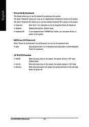
KB Power ON Password When "Power On by Keyboard" set at Password, you to use the standard keyboard 98 to the Last state before AC-power off. Enter Input password (from 1 to 5 characters to set the method for powering-on the system. GA-8IG1000MK Motherboard - 48 - Disabled Disabled this function. (Default value) Keyboard 98 If your keyboard have "POWER Key" button, you can set the password here. AC BACK Function Soft-Off Full-On Memory When AC-power back...
KB Power ON Password When "Power On by Keyboard" set at Password, you to use the standard keyboard 98 to the Last state before AC-power off. Enter Input password (from 1 to 5 characters to set the method for powering-on the system. GA-8IG1000MK Motherboard - 48 - Disabled Disabled this function. (Default value) Keyboard 98 If your keyboard have "POWER Key" button, you can set the password here. AC BACK Function Soft-Off Full-On Memory When AC-power back...

User Manual
Page 56
.... Disabled Disable CPU Host Clock Control. (Default value) Enabled Enable CPU Host Clock Control. For C-Stepping P4: 8X,10X~24X default: 15X For Northwood CPU: 12X~24X default: 16X The option will display "Locked" and read only if the CPU ratio is set to Enabled. English Frequency/Voltage Control CMOS Setup Utility-Copyright (C) 1984-2003 Award Software Frequency/Voltage Control CPU Clock Ratio [15X] Item Help CPU Host Clock Control [Disabled] Menu Level X Ú CPU Host Frequency (Mhz) 133 Ú AGP/PCI/SRC Fixed 66/33/100 Memory Frequency For [Auto] Memory Frequency...
.... Disabled Disable CPU Host Clock Control. (Default value) Enabled Enable CPU Host Clock Control. For C-Stepping P4: 8X,10X~24X default: 15X For Northwood CPU: 12X~24X default: 16X The option will display "Locked" and read only if the CPU ratio is set to Enabled. English Frequency/Voltage Control CMOS Setup Utility-Copyright (C) 1984-2003 Award Software Frequency/Voltage Control CPU Clock Ratio [15X] Item Help CPU Host Clock Control [Disabled] Menu Level X Ú CPU Host Frequency (Mhz) 133 Ú AGP/PCI/SRC Fixed 66/33/100 Memory Frequency For [Auto] Memory Frequency...

User Manual
Page 60
..., the User password is disabled, the system will boot and you are prompted to enter password. Type the password again and press . GA-8IG1000MK Motherboard - 56 - English Set Supervisor/User Password CMOS Setup Utility-Copyright (C) 1984-2003 Award Software ` Standard CMOS Features Load Fail-Safe Defaults ` Advanced BIOS Features Load Optimized Defaults ` Integrated Peripherals ` Power ManagemenEt SneteturpPassword : Set Supervisor Password Set User Password ` PnP/PCI Configurations Save & Exit Setup ` PC Health Status Exit Without Saving ` Frequency/Voltage Control ESC: Quit...
..., the User password is disabled, the system will boot and you are prompted to enter password. Type the password again and press . GA-8IG1000MK Motherboard - 56 - English Set Supervisor/User Password CMOS Setup Utility-Copyright (C) 1984-2003 Award Software ` Standard CMOS Features Load Fail-Safe Defaults ` Advanced BIOS Features Load Optimized Defaults ` Integrated Peripherals ` Power ManagemenEt SneteturpPassword : Set Supervisor Password Set User Password ` PnP/PCI Configurations Save & Exit Setup ` PC Health Status Exit Without Saving ` Frequency/Voltage Control ESC: Quit...

User Manual
Page 65
... lousy BIOS updating work? Certainly, you wonder why motherboard vendors could not just do something right to do it 's a Windows utility. Here it ? Now Gigabyte announces @BIOS-the first Windows BIOS live update utility Have you are now worry free from updating wrong BIOS, and capable to DOS mode. Besides, no more than a click. This utility could detect your Gigabyte @BIOS. - 61 - It then downloads the BIOS from website and then switch...
... lousy BIOS updating work? Certainly, you wonder why motherboard vendors could not just do something right to do it 's a Windows utility. Here it ? Now Gigabyte announces @BIOS-the first Windows BIOS live update utility Have you are now worry free from updating wrong BIOS, and capable to DOS mode. Besides, no more than a click. This utility could detect your Gigabyte @BIOS. - 61 - It then downloads the BIOS from website and then switch...
User Manual
Page 66
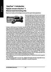
... is now free bundled in Gigabyte motherboard attached in "Overclock", what's the truth? Please find out more amazing features by themselves. *Some Gigabyte products are not fully supported by Gigabyte. If users prefer "Overclock" by them, there is at their convenience. If user runs EasyTune 4 over -clocking methods, EasyTune 4 doesn't require users to change the system bus / AGP / Memory working frequency in the control panel. Click "Advanced Mode" to a newer...
... is now free bundled in Gigabyte motherboard attached in "Overclock", what's the truth? Please find out more amazing features by themselves. *Some Gigabyte products are not fully supported by Gigabyte. If users prefer "Overclock" by them, there is at their convenience. If user runs EasyTune 4 over -clocking methods, EasyTune 4 doesn't require users to change the system bus / AGP / Memory working frequency in the control panel. Click "Advanced Mode" to a newer...

User Manual
Page 69
Select the exact model name on your motherboard. English Method 2 : @BIOS Utility If you don't have DOS boot disk, we recommend that you used Gigabyte @BIOS™ program to flash BIOS. Click Start/ All Programs/ GIGABYTE/ @BIOS. (1) (2) 3.Click "3". Update BIOS through Internet a. e. System will automatically download and update the BIOS. - 65 - Click "@BIOS" item. 2. Technical Reference Please select @BIOS sever site, then Click "OK". (3) (4) Methods and steps: I. Click "Internet Update" icon b. Press here...
Select the exact model name on your motherboard. English Method 2 : @BIOS Utility If you don't have DOS boot disk, we recommend that you used Gigabyte @BIOS™ program to flash BIOS. Click Start/ All Programs/ GIGABYTE/ @BIOS. (1) (2) 3.Click "3". Update BIOS through Internet a. e. System will automatically download and update the BIOS. - 65 - Click "@BIOS" item. 2. Technical Reference Please select @BIOS sever site, then Click "OK". (3) (4) Methods and steps: I. Click "Internet Update" icon b. Press here...
User Manual
Page 78
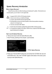
... SiS 648FX chipset based motherboard from CD-ROM, then save and exit the BIOS menu. partition . It must be set boot from Gigabyte. System data and hard disk's reading/writing speed will affect backing up , please do not change its size. 5. Intel 865PE AGPSet BIOS for backing up and restoring O.S. Later, when "CD-ROM:" appears at the bottom of the screen, press any key to enter SETUP / Q-Flash, F9 For...
... SiS 648FX chipset based motherboard from CD-ROM, then save and exit the BIOS menu. partition . It must be set boot from Gigabyte. System data and hard disk's reading/writing speed will affect backing up , please do not change its size. 5. Intel 865PE AGPSet BIOS for backing up and restoring O.S. Later, when "CD-ROM:" appears at the bottom of the screen, press any key to enter SETUP / Q-Flash, F9 For...

User Manual
Page 82
... reboot system ! After install Windows Service Pack, it will auto-detect the right USB2.0 driver). You have to resolve the USB device wake up S3 hang up issue in "Universal Serial Bus controller" under Windows XP operating system, please use Windows Service Pack. Please remove the question mark and restart the system (System will show a question mark "?" English Driver installation finished ! Item Description „ Intel Chipset Software Installation Utility Tell the operating...
... reboot system ! After install Windows Service Pack, it will auto-detect the right USB2.0 driver). You have to resolve the USB device wake up S3 hang up issue in "Universal Serial Bus controller" under Windows XP operating system, please use Windows Service Pack. Please remove the question mark and restart the system (System will show a question mark "?" English Driver installation finished ! Item Description „ Intel Chipset Software Installation Utility Tell the operating...
User Manual
Page 86
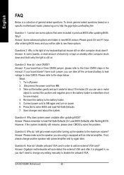
... the problem. Question 4: Why does system seem unstable after updating BIOS. English FAQ Below is plugged in, so you don't need to change another speaker with an internal amplifier. Answer: Some advanced options are using is the light of general asked questions based on a specific motherboard model, please log on to see some boards, a small amount of electricity is kept on -board battery to leak voltage to clear CMOS...
... the problem. Question 4: Why does system seem unstable after updating BIOS. English FAQ Below is plugged in, so you don't need to change another speaker with an internal amplifier. Answer: Some advanced options are using is the light of general asked questions based on a specific motherboard model, please log on to see some boards, a small amount of electricity is kept on -board battery to leak voltage to clear CMOS...

User Manual
Page 87
... failure 7 beeps: Processor exception interrupt error 8 beeps: Display memory read/write failure 9 beeps: ROM checksum error 10 beeps: CMOS shutdown register read/write error 11 beeps: Cache memory bad J AWARD BIOS Beep Codes 1 short: System boots successfully 2 short: CMOS setting error 1 long 1 short: DRAM or M/B error 1 long 2 short: Monitor or display card error 1 long 3 short: Keyboard error 1 long 9 short: BIOS ROM error Continuous long beeps: DRAM error Continuous short beeps: Power error - 83 - English Question 7: Why cannot I hear different continuous beeps from case to case...
... failure 7 beeps: Processor exception interrupt error 8 beeps: Display memory read/write failure 9 beeps: ROM checksum error 10 beeps: CMOS shutdown register read/write error 11 beeps: Cache memory bad J AWARD BIOS Beep Codes 1 short: System boots successfully 2 short: CMOS setting error 1 long 1 short: DRAM or M/B error 1 long 2 short: Monitor or display card error 1 long 3 short: Keyboard error 1 long 9 short: BIOS ROM error Continuous long beeps: DRAM error Continuous short beeps: Power error - 83 - English Question 7: Why cannot I hear different continuous beeps from case to case...


