Manual
Page 2
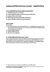
...if you do not want to the hard drive(s). Then connect the power connector from your power supply to create RAID array on the motherboard. (To ensure that your IDE CD-ROM drive can work properly, please connect it to ensure optimal performance, it is recommended that...controller). If you may prepare only one hard drive. (b) An empty formatted floppy disk. (c) Windows XP/2000 setup disk. (d) Driver CD for your motherboard. (1) Installing IDE hard drive(s) in RAID BIOS. (4) Make a floppy disk containing the IDE RAID controller driver (5) Install the IDE RAID controller driver during...
...if you do not want to the hard drive(s). Then connect the power connector from your power supply to create RAID array on the motherboard. (To ensure that your IDE CD-ROM drive can work properly, please connect it to ensure optimal performance, it is recommended that...controller). If you may prepare only one hard drive. (b) An empty formatted floppy disk. (c) Windows XP/2000 setup disk. (d) Driver CD for your motherboard. (1) Installing IDE hard drive(s) in RAID BIOS. (4) Make a floppy disk containing the IDE RAID controller driver (5) Install the IDE RAID controller driver during...
Manual
Page 3
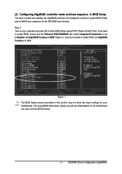
... Integrated Peripherals is set BIOS boot sequence for your computer and press Del to RAID (Figure 1). IDE RAID Drives Configuration (GigaRAID) Step 1: Turn on the motherboard you want to create RAID, set GigaRAID Function to make sure whether the GigaRAID controller are configured correctly in this section may not show the... Setup during POST (Power-On Self Test). If you have to ATA. The actual BIOS Setup menu options you will see shall depend on your motherboard.
... Integrated Peripherals is set BIOS boot sequence for your computer and press Del to RAID (Figure 1). IDE RAID Drives Configuration (GigaRAID) Step 1: Turn on the motherboard you want to create RAID, set GigaRAID Function to make sure whether the GigaRAID controller are configured correctly in this section may not show the... Setup during POST (Power-On Self Test). If you have to ATA. The actual BIOS Setup menu options you will see shall depend on your motherboard.
Manual
Page 14
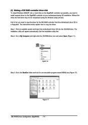
... install Windows 2000/XP onto a hard drive on the GigaRAID controller successfully, you need to install required driver for the GigaRAID controller on your motherboard during the Windows setup process. ¤å First of all, you need to copy the driver for an executable program named MENU.exe (Figure...ROM drive. Quit the installation utility first. Figure 16 Step 3: Go to the BootDrv folder and look for the IDE RAID controller from the motherboard driver CD to a floppydisk. The instructions below explain how to My Computer and right-click the CD-ROM drive icon and select Open (...
... install Windows 2000/XP onto a hard drive on the GigaRAID controller successfully, you need to install required driver for the GigaRAID controller on your motherboard during the Windows setup process. ¤å First of all, you need to copy the driver for an executable program named MENU.exe (Figure...ROM drive. Quit the installation utility first. Figure 16 Step 3: Go to the BootDrv folder and look for the IDE RAID controller from the motherboard driver CD to a floppydisk. The instructions below explain how to My Computer and right-click the CD-ROM drive icon and select Open (...
Manual
Page 15
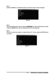
Step 3: Double-click MENU.exe. IDE RAID Drives Configuration (GigaRAID) Figure 19 - 15 - Figure 18 Step 4: Insert an empty floppy disk. You have copied the IDE RAID driver sucessfully. Press 2 to Figure 18 below will take about one minute to copy the GigaRAID driver from the motherboard driver CD to exit when the procedure is complete (Figure 19). An MS-DOS prompt screen similar to select the 2)GIGARAID item. Step 5: Press 0 to the floppy disk. Then it will appear.
Step 3: Double-click MENU.exe. IDE RAID Drives Configuration (GigaRAID) Figure 19 - 15 - Figure 18 Step 4: Insert an empty floppy disk. You have copied the IDE RAID driver sucessfully. Press 2 to Figure 18 below will take about one minute to copy the GigaRAID driver from the motherboard driver CD to exit when the procedure is complete (Figure 19). An MS-DOS prompt screen similar to select the 2)GIGARAID item. Step 5: Press 0 to the floppy disk. Then it will appear.
Manual
Page 17
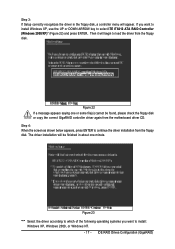
... the floppy disk. Figure 23 "*" Select the driver according to which of the following operating systems you want to continue the driver installation from the motherboard driver CD. The driver installation will begin to select ITE IT8212 ATA RAID Controller (Windows 2000/XP)* (Figure 22) and press ENTER. Step 3: If Setup...
... the floppy disk. Figure 23 "*" Select the driver according to which of the following operating systems you want to continue the driver installation from the motherboard driver CD. The driver installation will begin to select ITE IT8212 ATA RAID Controller (Windows 2000/XP)* (Figure 22) and press ENTER. Step 3: If Setup...
Manual
Page 72
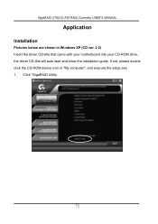
GigaRAID (IT8212) ATA RAID Controller USER'S MANUAL Application Installation Pictures below are shown in "My computer", and execute the setup.exe. 1. If not, please double click the CD-ROM device icon in Windows XP (CD ver. 2.2) Insert the driver CD-title that came with your motherboard into your CD-ROM drive, the driver CD-title will auto start and show the installation guide. Click "GigaRAID Utility. 72
GigaRAID (IT8212) ATA RAID Controller USER'S MANUAL Application Installation Pictures below are shown in "My computer", and execute the setup.exe. 1. If not, please double click the CD-ROM device icon in Windows XP (CD ver. 2.2) Insert the driver CD-title that came with your motherboard into your CD-ROM drive, the driver CD-title will auto start and show the installation guide. Click "GigaRAID Utility. 72
Manual
Page 1
GA-8I945PL-G Intel® Pentium® D / Pentium® 4 LGA775 Processor Motherboard User's Manual Rev. 1002 12ME-8I945PLG-1002R * The WEEE marking on the product indicates this product must not be disposed of with user's other household waste and must be handed over to a designated collection point for the recycling of waste electrical and electronic equipment!! * The WEEE marking applies only in European Union's member states.
GA-8I945PL-G Intel® Pentium® D / Pentium® 4 LGA775 Processor Motherboard User's Manual Rev. 1002 12ME-8I945PLG-1002R * The WEEE marking on the product indicates this product must not be disposed of with user's other household waste and must be handed over to a designated collection point for the recycling of waste electrical and electronic equipment!! * The WEEE marking applies only in European Union's member states.
Manual
Page 2
Motherboard GA-8I945PL-G Sep. 28, 2005 Motherboard GA-8I945PL-G Sep. 28, 2005
Motherboard GA-8I945PL-G Sep. 28, 2005 Motherboard GA-8I945PL-G Sep. 28, 2005
Manual
Page 4
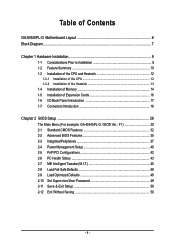
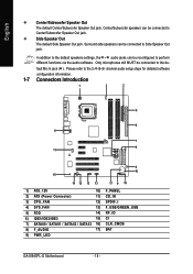
Table of Contents GA-8I945PL-G Motherboard Layout 6 Block Diagram ...7 Chapter 1 Hardware Installation 9 1-1 Considerations Prior to Installation 9 1-2 Feature Summary 10 1-3 Installation of the CPU and Heatsink 12 1-3-1 Installation...of Memory 14 1-5 Installation of Expansion Cards 16 1-6 I/O Back Panel Introduction 17 1-7 Connectors Introduction 18 Chapter 2 BIOS Setup 29 The Main Menu (For example: GA-8I945PL-G / BIOS Ver.: F1 30 2-1 Standard CMOS Features 32 2-2 Advanced BIOS Features 35 2-3 IntegratedPeripherals 37 2-4 Power Management Setup 40 2-5 PnP/PCI Configurations 42 ...
Table of Contents GA-8I945PL-G Motherboard Layout 6 Block Diagram ...7 Chapter 1 Hardware Installation 9 1-1 Considerations Prior to Installation 9 1-2 Feature Summary 10 1-3 Installation of the CPU and Heatsink 12 1-3-1 Installation...of Memory 14 1-5 Installation of Expansion Cards 16 1-6 I/O Back Panel Introduction 17 1-7 Connectors Introduction 18 Chapter 2 BIOS Setup 29 The Main Menu (For example: GA-8I945PL-G / BIOS Ver.: F1 30 2-1 Standard CMOS Features 32 2-2 Advanced BIOS Features 35 2-3 IntegratedPeripherals 37 2-4 Power Management Setup 40 2-5 PnP/PCI Configurations 42 ...
Manual
Page 6
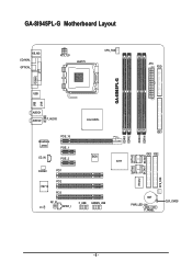
GA-8I945PL-G Motherboard Layout KB_MS COAXIAL OPTICAL ATX_12V LGA775 CPU_FAN ATX FDD LPT GA-8I945PL-G COMA USB LAN USB AUDIO1 AUDIO2 F_AUDIO Intel 945PL Broadcom 5789 PCIE_16 PCIE_1 CD_IN PCIE_2 BIOS CODEC PCI1 IT8712 PCI2 PCI3 RF_ID F_USB GREEN_USB CI SPDIF_I ICH7 DDRII1 DDRII2 DDRII3 DDRII4 IDE1 IDE3 IDE2 SATAII0 SATAII2 IT8212 SATAII1 SATAII3 SYS_FAN BAT PWR_LED F_PANEL CLR_CMOS - 6 -
GA-8I945PL-G Motherboard Layout KB_MS COAXIAL OPTICAL ATX_12V LGA775 CPU_FAN ATX FDD LPT GA-8I945PL-G COMA USB LAN USB AUDIO1 AUDIO2 F_AUDIO Intel 945PL Broadcom 5789 PCIE_16 PCIE_1 CD_IN PCIE_2 BIOS CODEC PCI1 IT8712 PCI2 PCI3 RF_ID F_USB GREEN_USB CI SPDIF_I ICH7 DDRII1 DDRII2 DDRII3 DDRII4 IDE1 IDE3 IDE2 SATAII0 SATAII2 IT8212 SATAII1 SATAII3 SYS_FAN BAT PWR_LED F_PANEL CLR_CMOS - 6 -

Manual
Page 9
...conditions recommended in contact with the motherboard circuit or its power cord....motherboard. Damage due to the installation of the motherboard or any hardware, please first carefully read the information in the provided manual. 3. When handling the motherboard..., avoid touching any installation steps or have these items on the motherboard or...motherboard. Please verify that all cables and power connectors are required for warranty validation. 2. To prevent damage to the motherboard...Installation Preparing Your Computer The motherboard contains numerous delicate electronic ...
...conditions recommended in contact with the motherboard circuit or its power cord....motherboard. Damage due to the installation of the motherboard or any hardware, please first carefully read the information in the provided manual. 3. When handling the motherboard..., avoid touching any installation steps or have these items on the motherboard or...motherboard. Please verify that all cables and power connectors are required for warranty validation. 2. To prevent damage to the motherboard...Installation Preparing Your Computer The motherboard contains numerous delicate electronic ...
Manual
Page 10
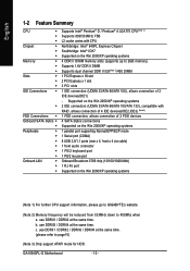
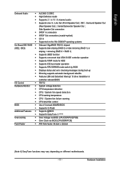
.../100/1000 Mbit) 1 RJ 45 port Supported on the Win 2000/XP operating systems (Note 1) For further CPU support information, please go to GIGABYTE's website. (Note 2) Memory frequency will be reduced from 533MHz down to page15) (Note 3) Only support ATAPI mode for HDD. GA-8I945PL-G Motherboard - 10 - use DDRII3 / DDRII4 at the same time. b.
.../100/1000 Mbit) 1 RJ 45 port Supported on the Win 2000/XP operating systems (Note 1) For further CPU support information, please go to GIGABYTE's website. (Note 2) Memory frequency will be reduced from 533MHz down to page15) (Note 3) Only support ATAPI mode for HDD. GA-8I945PL-G Motherboard - 10 - use DDRII3 / DDRII4 at the same time. b.
Manual
Page 11
...; Over Clock via BIOS (CPU/DDR/PCIE) Form Factor Š ATX form factor; 30.5cm x 22.0cm (Note 4) EasyTune functions may vary depending on different motherboards. - 11 - Line Out (Front Speaker Out) ; MIC ; English Onboard Audio Š ALC882 CODEC Š High Definition Audio Š Supports 2 / 4 / 6 / 8 channel audio Š Supports Line In...
...; Over Clock via BIOS (CPU/DDR/PCIE) Form Factor Š ATX form factor; 30.5cm x 22.0cm (Note 4) EasyTune functions may vary depending on different motherboards. - 11 - Line Out (Front Speaker Out) ; MIC ; English Onboard Audio Š ALC882 CODEC Š High Definition Audio Š Supports 2 / 4 / 6 / 8 channel audio Š Supports Line In...
Manual
Page 12
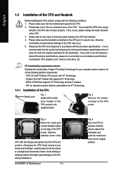
...install the CPU in a straight and downwards motion. Fig. 2 Remove the plastic covering on the CPU prior to the CPU during installation.) GA-8I945PL-G Motherboard - 12 - Align the indented corner of the CPU with the following platform components: - Please make sure the heatsink is installed on the ... might cause damage to system use, otherwise overheating and permanent damage of the CPU may occur. 5. BIOS: A BIOS that the motherboard supports the CPU. 2. Please add an even layer of heat sink paste between your thumb and forefinger, carefully place it does not...
...install the CPU in a straight and downwards motion. Fig. 2 Remove the plastic covering on the CPU prior to the CPU during installation.) GA-8I945PL-G Motherboard - 12 - Align the indented corner of the CPU with the following platform components: - Please make sure the heatsink is installed on the ... might cause damage to system use, otherwise overheating and permanent damage of the CPU may occur. 5. BIOS: A BIOS that the motherboard supports the CPU. 2. Please add an even layer of heat sink paste between your thumb and forefinger, carefully place it does not...

Manual
Page 13
... the Heatsink Male Push Pin The top of Female Push Pin Female Push Pin Fig.1 Please apply an even layer of heatsink paste on the motherboard. Fig. 4 Please make sure the push pins aim to the pin hole on the male push pin doesn't face inwards before installation. (This instruction ...when removing the heatsink. - 13 - If the push pin is to the heatsink installation section of the user manual) Fig. 5 Please check the back of motherboard after installing. Fig. 2 (Turning the push pin along the direction of arrow is to remove the heatsink, on the contrary, is inserted as a result of...
... the Heatsink Male Push Pin The top of Female Push Pin Female Push Pin Fig.1 Please apply an even layer of heatsink paste on the motherboard. Fig. 4 Please make sure the push pins aim to the pin hole on the male push pin doesn't face inwards before installation. (This instruction ...when removing the heatsink. - 13 - If the push pin is to the heatsink installation section of the user manual) Fig. 5 Please check the back of motherboard after installing. Fig. 2 (Turning the push pin along the direction of arrow is to remove the heatsink, on the contrary, is inserted as a result of...
Manual
Page 14
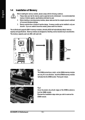
...so the DIMM memory module can be used. 2. Then push it down. Insert the DIMM memory module vertically into the DIMM socket. GA-8I945PL-G Motherboard - 14 - The memory capacity used is switched off to remove the DIMM module. Before installing or removing memory modules, please make... sure that the computer power is supported by the motherboard. A memory module can differ with the following conditions: 1. Reverse the installation steps when you are designed so that memory of...
...so the DIMM memory module can be used. 2. Then push it down. Insert the DIMM memory module vertically into the DIMM socket. GA-8I945PL-G Motherboard - 14 - The memory capacity used is switched off to remove the DIMM module. Before installing or removing memory modules, please make... sure that the computer power is supported by the motherboard. A memory module can differ with the following conditions: 1. Reverse the installation steps when you are designed so that memory of...
Manual
Page 16
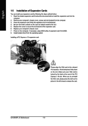
... the steps outlined below: 1. Replace the screw to the onboard PCI Express x 16 slot and press firmly down on the card are indeed seated in motherboard. 4. GA-8I945PL-G Motherboard - 16 - Press the expansion card firmly into the computer. 2. Installing a PCI Express x 16 expansion card: Please align the VGA card to secure the slot bracket...
... the steps outlined below: 1. Replace the screw to the onboard PCI Express x 16 slot and press firmly down on the card are indeed seated in motherboard. 4. GA-8I945PL-G Motherboard - 16 - Press the expansion card firmly into the computer. 2. Installing a PCI Express x 16 expansion card: Please align the VGA card to secure the slot bracket...
Manual
Page 18
... 3) CPU_FAN 12) SPDIF_I 4) SYS_FAN 13) F_USB/GREEN_USB 5) FDD 14) RF_ID 6) IDE1/IDE2/IDE3 15) CI 7) SATAII0 / SATAII1 / SATAII2 / SATAII3 16) CLR_CMOS 8) F_AUDIO 17) BAT 9) PWR_LED GA-8I945PL-G Motherboard - 18 - Only microphones still MUST be connected to the 2-/4-/6-/8-
... 3) CPU_FAN 12) SPDIF_I 4) SYS_FAN 13) F_USB/GREEN_USB 5) FDD 14) RF_ID 6) IDE1/IDE2/IDE3 15) CI 7) SATAII0 / SATAII1 / SATAII2 / SATAII3 16) CLR_CMOS 8) F_AUDIO 17) BAT 9) PWR_LED GA-8I945PL-G Motherboard - 18 - Only microphones still MUST be connected to the 2-/4-/6-/8-

Manual
Page 19
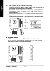
... devices are properly installed. If you use a 24-pin ATX power supply, please remove the small cover on the power connector on the motherboard and connect tightly. If the ATX_12V power connector is able to handle the system voltage requirements. Otherwise, please do not remove it. Definition ... (300W or greater). If a power supply is unable to start . Caution! Align the power connector with its proper location on the motherboard before plugging in the power cord ; Hardware Installation English 1/2) ATX_12V/ATX (Power Connector) With the use of the power connector, the...
... devices are properly installed. If you use a 24-pin ATX power supply, please remove the small cover on the power connector on the motherboard and connect tightly. If the ATX_12V power connector is able to handle the system voltage requirements. Otherwise, please do not remove it. Definition ... (300W or greater). If a power supply is unable to start . Caution! Align the power connector with its proper location on the motherboard before plugging in the power cord ; Hardware Installation English 1/2) ATX_12V/ATX (Power Connector) With the use of the power connector, the...
Manual
Page 20
... connector wire indicates a positive connection and requires a +12V power voltage. Please remember to connect the power to the cooler to the pin1 position. 34 33 GA-8I945PL-G Motherboard 2 1 - 20 -
... connector wire indicates a positive connection and requires a +12V power voltage. Please remember to connect the power to the cooler to the pin1 position. 34 33 GA-8I945PL-G Motherboard 2 1 - 20 -


