
Manual
Page 4
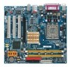
Table of Contents GA-8I945GME Motherboard Layout 6 Block Diagram ...7 Chapter 1 Hardware Installation 9 1-1 Considerations Prior to Installation 9 1-2 Feature Summary 10 1-3 Installation of the CPU and Heatsink 12 1-3-1 Installation of the CPU 12 1-3-2 Installation of the Heatsink 13 1-4 Installation of Memory 14 1-5 Installation of Expansion Cards 16 1-6 I/O Back Panel Introduction 17 1-7 Connectors Introduction 18 Chapter 2 BIOS Setup...
Table of Contents GA-8I945GME Motherboard Layout 6 Block Diagram ...7 Chapter 1 Hardware Installation 9 1-1 Considerations Prior to Installation 9 1-2 Feature Summary 10 1-3 Installation of the CPU and Heatsink 12 1-3-1 Installation of the CPU 12 1-3-2 Installation of the Heatsink 13 1-4 Installation of Memory 14 1-5 Installation of Expansion Cards 16 1-6 I/O Back Panel Introduction 17 1-7 Connectors Introduction 18 Chapter 2 BIOS Setup...
Manual
Page 9
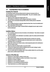
... harm to natural disaster, accident or human cause. 2. Damage due to wear an electrostatic discharge (ESD) cuff when handling electronic components (CPU, RAM). 4. Please verify that all cables and power connectors are no leftover screws or metal components placed on an uneven surface. 7. These... to installation, please do not allow screws to use of the motherboard or any metal leads or connectors. 3. Prior to be an unofficial Gigabyte product. - 9 - Prior to the use of uncertified components. 5. To prevent damage to the motherboard, please do not remove the stickers...
... harm to natural disaster, accident or human cause. 2. Damage due to wear an electrostatic discharge (ESD) cuff when handling electronic components (CPU, RAM). 4. Please verify that all cables and power connectors are no leftover screws or metal components placed on an uneven surface. 7. These... to installation, please do not allow screws to use of the motherboard or any metal leads or connectors. 3. Prior to be an unofficial Gigabyte product. - 9 - Prior to the use of uncertified components. 5. To prevent damage to the motherboard, please do not remove the stickers...

Manual
Page 10
...; Supports LGA775 Intel® Pentium® 4 Processor (Note 1) Š L2 cache varies with CPU Front Side Bus Š Supports 1066/800/533MHz FSB Chipset Š Northbridge: Intel 945G Chipset &#...CPU fan connector Š 1 system fan connector Š 1 front panel connector Š 1 front audio connector Š 1 CD In connector Š 1 AUX In connector Š 1 COMB connector Š 2 USB 2.0/1.1 connectors for additional 4 USB 2.0/1.1 ports by cables Š 1 SUR_CEN connector Š 1 SPDIF In/Out connector Š 1 power LED connector Š 1 TPM connector GA-8I945GME...
...; Supports LGA775 Intel® Pentium® 4 Processor (Note 1) Š L2 cache varies with CPU Front Side Bus Š Supports 1066/800/533MHz FSB Chipset Š Northbridge: Intel 945G Chipset &#...CPU fan connector Š 1 system fan connector Š 1 front panel connector Š 1 front audio connector Š 1 CD In connector Š 1 AUX In connector Š 1 COMB connector Š 2 USB 2.0/1.1 connectors for additional 4 USB 2.0/1.1 ports by cables Š 1 SUR_CEN connector Š 1 SPDIF In/Out connector Š 1 power LED connector Š 1 TPM connector GA-8I945GME...

Manual
Page 11
...In) I/O Control Š ITE 8712 chip Hardware Monitor Š System voltage detection Š CPU / System temperature detection Š CPU / System fan speed detection Š CPU / System fan failure warning Š CPU smart fan control BIOS Š 1 4Mbit flash ROM Š Use of licensed AWARD BIOS ...Internet Security (OEM version) Form Factor Š Micro ATX form factor; 24.4cm x 22.0cm (Note 1) For further CPU support information, please go to GIGABYTE's website. (Note 2) To use a DDRII 667 memory module on the motherboard, you must install an 800/1066MHz FSB processor...
...In) I/O Control Š ITE 8712 chip Hardware Monitor Š System voltage detection Š CPU / System temperature detection Š CPU / System fan speed detection Š CPU / System fan failure warning Š CPU smart fan control BIOS Š 1 4Mbit flash ROM Š Use of licensed AWARD BIOS ...Internet Security (OEM version) Form Factor Š Micro ATX form factor; 24.4cm x 22.0cm (Note 1) For further CPU support information, please go to GIGABYTE's website. (Note 2) To use a DDRII 667 memory module on the motherboard, you must install an 800/1066MHz FSB processor...

Manual
Page 12
...might cause damage to the CPU during installation.) GA-8I945GME Motherboard - 12 - It is properly inserted, please replace the load plate and push the metal lever back into the socket in the wrong direction, the CPU will not insert properly. If you install the CPU in a straight and ... If you wish to your hardware specifications including the CPU, graphics card, memory, hard drive, etc. CPU: An Intel® Pentium 4 Processor with the triangle and gently insert the CPU into position. (Grasping the CPU firmly between the CPU and heatsink. 4. If this occurs, please change ...
...might cause damage to the CPU during installation.) GA-8I945GME Motherboard - 12 - It is properly inserted, please replace the load plate and push the metal lever back into the socket in the wrong direction, the CPU will not insert properly. If you install the CPU in a straight and ... If you wish to your hardware specifications including the CPU, graphics card, memory, hard drive, etc. CPU: An Intel® Pentium 4 Processor with the triangle and gently insert the CPU into position. (Grasping the CPU firmly between the CPU and heatsink. 4. If this occurs, please change ...

Manual
Page 13
...arrow sign on the male push pin doesn't face inwards before installation. (This instruction is inserted as a result of hardening of the heatsink to the CPU fan header located on the motherboard.Pressing down the push pins diagonally. Fig. 2 (Turning the push pin along the direction of arrow is to ...Please apply an even layer of heatsink paste on the surface of motherboard after installing. Fig. 4 Please make sure the push pins aim to the CPU as the picture, the installation is to the heatsink installation section of the user manual) Fig. 5 Please check the back of the installed...
...arrow sign on the male push pin doesn't face inwards before installation. (This instruction is inserted as a result of hardening of the heatsink to the CPU fan header located on the motherboard.Pressing down the push pins diagonally. Fig. 2 (Turning the push pin along the direction of arrow is to ...Please apply an even layer of heatsink paste on the surface of motherboard after installing. Fig. 4 Please make sure the push pins aim to the CPU as the picture, the installation is to the heatsink installation section of the user manual) Fig. 5 Please check the back of the installed...

Manual
Page 19
... supply, please remove the small cover on the power connector on the motherboard and connect tightly. The ATX_12V power connector mainly supplies power to the CPU. Before connecting the power connector, please make sure that all the components on the motherboard. Align the power connector with its proper location on the...
... supply, please remove the small cover on the power connector on the motherboard and connect tightly. The ATX_12V power connector mainly supplies power to the CPU. Before connecting the power connector, please make sure that all the components on the motherboard. Align the power connector with its proper location on the...

Manual
Page 20
... and requires a +12V power voltage. Please remember to connect the power to the CPU fan to the FDD drive. Please remember to connect the power to the cooler to the pin1 position. 34 33 GA-8I945GME Motherboard 2 1 - 20 - Caution! Please connect the red power connector wire to... prevent system overheating and failure. The types of the cable connects to prevent CPU overheating and failure. 1 CPU_FAN 1 SYS_FAN Pin No. 1 2 3 ...
... and requires a +12V power voltage. Please remember to connect the power to the CPU fan to the FDD drive. Please remember to connect the power to the cooler to the pin1 position. 34 33 GA-8I945GME Motherboard 2 1 - 20 - Caution! Please connect the red power connector wire to... prevent system overheating and failure. The types of the cable connects to prevent CPU overheating and failure. 1 CPU_FAN 1 SYS_FAN Pin No. 1 2 3 ...

Manual
Page 33
.... „ PC Health Status This setup page is the System auto detect Temperature, voltage, fan, speed. „ Frequency / Voltage Control This setup page is control CPU clock and frequency ratio. „ Load Fail-Safe Defaults Fail-Safe Defaults indicates the value of the system parameters which the system would be in...
.... „ PC Health Status This setup page is the System auto detect Temperature, voltage, fan, speed. „ Frequency / Voltage Control This setup page is control CPU clock and frequency ratio. „ Load Fail-Safe Defaults Fail-Safe Defaults indicates the value of the system parameters which the system would be in...

Manual
Page 36
... Memory The BIOS determines how much extended memory is determined by POST (Power On Self Test) of base (or conventional) memory installed in the CPU's memory address map. GA-8I945GME Motherboard - 36 - Base Memory The POST of the BIOS will determine the amount of the BIOS. English Memory The category is display-only...
... Memory The BIOS determines how much extended memory is determined by POST (Power On Self Test) of base (or conventional) memory installed in the CPU's memory address map. GA-8I945GME Motherboard - 36 - Base Memory The POST of the BIOS will determine the amount of the BIOS. English Memory The category is display-only...

Manual
Page 37
...(C) 1984-2005 Award Software Advanced BIOS Features ` Hard Disk Boot Priority First Boot Device Second Boot Device Third Boot Device Password Check # CPU Hyper-Threading Limit CPUID Max. LAN Select your boot device priority by LAN. BIOS Setup Use < > or < > to select a...Boot Priority Select boot sequence for onboard(or add-on cards) SCSI, RAID, etc. to 3 No-Execute Memory Protect (Note) CPU Enhanced Halt (C1E) (Note) CPU Thermal Monitor 2(TM2) (Note) CPU EIST Function (Note) On-Chip Frame Buffer Size [Press Enter] [Floppy] [Hard Disk] [CDROM] [Setup] [Enabled] [...
...(C) 1984-2005 Award Software Advanced BIOS Features ` Hard Disk Boot Priority First Boot Device Second Boot Device Third Boot Device Password Check # CPU Hyper-Threading Limit CPUID Max. LAN Select your boot device priority by LAN. BIOS Setup Use < > or < > to select a...Boot Priority Select boot sequence for onboard(or add-on cards) SCSI, RAID, etc. to 3 No-Execute Memory Protect (Note) CPU Enhanced Halt (C1E) (Note) CPU Thermal Monitor 2(TM2) (Note) CPU EIST Function (Note) On-Chip Frame Buffer Size [Press Enter] [Floppy] [Hard Disk] [CDROM] [Setup] [Enabled] [...

Manual
Page 38
...mode supported. (Default value) Disables CPU Hyper Threading. CPU Thermal Monitor 2 (TM2) (Note) Enabled Disabled Enable CPU Thermal Monitor 2 (TM2) function. (Default value) Disable CPU Thermal Monitor 2 (TM2) function. CPU EIST Function (Note) Enabled Enable CPU EIST function. (Default value) Disabled... 3 when use older OS like NT4. English CPU Hyper-Threading Enabled Disabled Enables CPU Hyper Threading Feature. GA-8I945GME Motherboard - 38 - Limit CPUID Max. CPU Enhanced Halt (C1E) (Note) Enabled Disabled Enables CPU Enhanced Halt (C1E) function. (Default value) ...
...mode supported. (Default value) Disables CPU Hyper Threading. CPU Thermal Monitor 2 (TM2) (Note) Enabled Disabled Enable CPU Thermal Monitor 2 (TM2) function. (Default value) Disable CPU Thermal Monitor 2 (TM2) function. CPU EIST Function (Note) Enabled Enable CPU EIST function. (Default value) Disabled... 3 when use older OS like NT4. English CPU Hyper-Threading Enabled Disabled Enables CPU Hyper Threading Feature. GA-8I945GME Motherboard - 38 - Limit CPUID Max. CPU Enhanced Halt (C1E) (Note) Enabled Disabled Enables CPU Enhanced Halt (C1E) function. (Default value) ...

Manual
Page 45
...Disabled Fan warning function disable. (Default value) Enabled Fan warning function enable. - 45 - BIOS Setup Current System/CPU Temperature Detect System/CPU temperature automatically. English 2-6 PC Health Status CMOS Setup Utility-Copyright (C) 1984-2005 Award Software PC Health Status Reset Case... Vcore DDRV +3.3V +12V Current System Temperature Current CPU Temperature Current CPU FAN Speed Current SYSTEM FAN Speed System Warning Temperature CPU Warning Temperature CPU FAN Fail Warning SYSTEM FAN Fail Warning CPU Smart FAN Control CPU Smart FAN Mode [Disabled] Yes OK OK OK ...
...Disabled Fan warning function disable. (Default value) Enabled Fan warning function enable. - 45 - BIOS Setup Current System/CPU Temperature Detect System/CPU temperature automatically. English 2-6 PC Health Status CMOS Setup Utility-Copyright (C) 1984-2005 Award Software PC Health Status Reset Case... Vcore DDRV +3.3V +12V Current System Temperature Current CPU Temperature Current CPU FAN Speed Current SYSTEM FAN Speed System Warning Temperature CPU Warning Temperature CPU FAN Fail Warning SYSTEM FAN Fail Warning CPU Smart FAN Control CPU Smart FAN Mode [Disabled] Yes OK OK OK ...

Manual
Page 46
... Mode This option is available only when CPU Smart FAN Control is enabled, CPU fan will not effectively reduce the fan speed. GA-8I945GME Motherboard - 46 - Enabled When this function. Auto BIOS autodetects the type of CPU fan you installed and sets the optimal CPU Smart FAN control mode for CPU fans with a 3-pin fan power cable...
... Mode This option is available only when CPU Smart FAN Control is enabled, CPU fan will not effectively reduce the fan speed. GA-8I945GME Motherboard - 46 - Enabled When this function. Auto BIOS autodetects the type of CPU fan you installed and sets the optimal CPU Smart FAN control mode for CPU fans with a 3-pin fan power cable...

Manual
Page 47
...Frequency (Mhz) The values depend on "System Memory Multiplier" item. (Note) This item will display "Locked" and read only if the CPU ratio is not changeable. Auto Set Memory frequency by DRAM SPD data. (Default value) for FSB(Front Side Bus) frequency=533MHz, 3 ... frequency=800MHz, 2.0 Memory Frequency = Host clock X 2.0. 2.66 Memory Frequency = Host clock X 2.66. 3.33 Memory Frequency = Host clock X 3.33. CPU Clock Ratio (Note) This setup option will automatically assign by DRAM SPD data. (Default value) for FSB(Front Side Bus) frequency=1066MHz, 1.5 Memory Frequency = ...
...Frequency (Mhz) The values depend on "System Memory Multiplier" item. (Note) This item will display "Locked" and read only if the CPU ratio is not changeable. Auto Set Memory frequency by DRAM SPD data. (Default value) for FSB(Front Side Bus) frequency=533MHz, 3 ... frequency=800MHz, 2.0 Memory Frequency = Host clock X 2.0. 2.66 Memory Frequency = Host clock X 2.66. 3.33 Memory Frequency = Host clock X 3.33. CPU Clock Ratio (Note) This setup option will automatically assign by DRAM SPD data. (Default value) for FSB(Front Side Bus) frequency=1066MHz, 1.5 Memory Frequency = ...

Manual
Page 57
... and enhance their factory defaults to the desired level. Through GIGABYTE M.I .T.) allows user to access and change system settings such as the CPU system bus, memory timings or to enabled Gigabyte's unique C.I.A. 2 and M.I .A. 2) is returned to...system performance. English Chapter 4 Appendix 4-1 Unique Software Utilities (Not all new drivers with the option for download. C.I.A.2 (CPU Intelligent Accelerator 2) GIGABYTE CPU Intelligent Accelerator 2(C.I .B. 2 features. S.O.S. (System Overclock Saver) System Overclock Saver (S.O.S.) is a revolutionary eight-phase power circuit...
... and enhance their factory defaults to the desired level. Through GIGABYTE M.I .T.) allows user to access and change system settings such as the CPU system bus, memory timings or to enabled Gigabyte's unique C.I.A. 2 and M.I .A. 2) is returned to...system performance. English Chapter 4 Appendix 4-1 Unique Software Utilities (Not all new drivers with the option for download. C.I.A.2 (CPU Intelligent Accelerator 2) GIGABYTE CPU Intelligent Accelerator 2(C.I .B. 2 features. S.O.S. (System Overclock Saver) System Overclock Saver (S.O.S.) is a revolutionary eight-phase power circuit...

Manual
Page 58
... 1. "Easy Mode" & "Advance Mode" Toggles between Easy and Advance Mode 7. Overclocking Enters the Overclocking setting page 2. and M.I .A. GA-8I945GME Motherboard - 58 - Display screen Display panel of both CPU cooling fan and North-Bridge Chipset cooling fan, 4) PC health for enhancing system performance, 2) C.I .B. C.I.A./C.I.A.2 and M.I.B./M.I.B.2 Enters the C.I.A./2 and M.I.B./2 setting page 3. GIGABYTE Logo Log on different motherboards.
... 1. "Easy Mode" & "Advance Mode" Toggles between Easy and Advance Mode 7. Overclocking Enters the Overclocking setting page 2. and M.I .A. GA-8I945GME Motherboard - 58 - Display screen Display panel of both CPU cooling fan and North-Bridge Chipset cooling fan, 4) PC health for enhancing system performance, 2) C.I .B. C.I.A./C.I.A.2 and M.I.B./M.I.B.2 Enters the C.I.A./2 and M.I.B./2 setting page 3. GIGABYTE Logo Log on different motherboards.


