
Manual
Page 4
...GA-8I945GME Motherboard Layout 6 Block Diagram ...7 Chapter 1 Hardware Installation 9 1-1 Considerations Prior to Installation 9 1-2 Feature Summary 10 1-3 Installation of the CPU and Heatsink 12 1-3-1 Installation of the CPU 12 1-3-2 Installation of the Heatsink 13 1-4 Installation of Memory 14 1-5 Installation of Expansion Cards 16 1-6 I/O Back Panel Introduction 17 1-7 Connectors Introduction 18 Chapter 2 BIOS... Setup 31 The Main Menu (For example: BIOS Ver. : D2 32 2-1 Standard CMOS Features 34 2-2 Advanced BIOS Features 37 2-3 ...
...GA-8I945GME Motherboard Layout 6 Block Diagram ...7 Chapter 1 Hardware Installation 9 1-1 Considerations Prior to Installation 9 1-2 Feature Summary 10 1-3 Installation of the CPU and Heatsink 12 1-3-1 Installation of the CPU 12 1-3-2 Installation of the Heatsink 13 1-4 Installation of Memory 14 1-5 Installation of Expansion Cards 16 1-6 I/O Back Panel Introduction 17 1-7 Connectors Introduction 18 Chapter 2 BIOS... Setup 31 The Main Menu (For example: BIOS Ver. : D2 32 2-1 Standard CMOS Features 34 2-2 Advanced BIOS Features 37 2-3 ...
Manual
Page 5
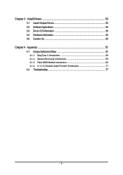
Chapter 3 Install Drivers 53 3-1 Install Chipset Drivers 53 3-2 SoftwareApplications 54 3-3 Driver CD Information 54 3-4 Hardware Information 55 3-5 Contact Us ...55 Chapter 4 Appendix 57 4-1 Unique Software Utilities 57 4-1-1 EasyTune 5 Introduction 58 4-1-2 Xpress Recovery2 Introduction 59 4-1-3 Flash BIOS Method Introduction 62 4-1-4 2 / 4 / 6 Channel Audio Function Introduction 71 4-2 Troubleshooting 77 - 5 -
Chapter 3 Install Drivers 53 3-1 Install Chipset Drivers 53 3-2 SoftwareApplications 54 3-3 Driver CD Information 54 3-4 Hardware Information 55 3-5 Contact Us ...55 Chapter 4 Appendix 57 4-1 Unique Software Utilities 57 4-1-1 EasyTune 5 Introduction 58 4-1-2 Xpress Recovery2 Introduction 59 4-1-3 Flash BIOS Method Introduction 62 4-1-4 2 / 4 / 6 Channel Audio Function Introduction 71 4-2 Troubleshooting 77 - 5 -

Manual
Page 6
GA-8I945GME Motherboard Layout KB_MS ATX_12V LGA775 CPU_FAN IT8712F COMA GA-8I945GME ATX LPT LAN VGA R_USB USB SYS_FAN AUDIO F_AUDIO PCIE_16 PCI1 RTL 8110S PCI2 SPDIF_IO CODEC PCI3 SUR_CEN CD_IN AUX_IN COMB Intel 945G DDRII2 DDRII1 IDE FDD SATAIIO SATAII2 SATAII1 SATAII3 ICH7 BAT CI BIOS TPM PWR_LED CLR_CMOS F_USB1F_USB2 F_PANEL - 6 -
GA-8I945GME Motherboard Layout KB_MS ATX_12V LGA775 CPU_FAN IT8712F COMA GA-8I945GME ATX LPT LAN VGA R_USB USB SYS_FAN AUDIO F_AUDIO PCIE_16 PCI1 RTL 8110S PCI2 SPDIF_IO CODEC PCI3 SUR_CEN CD_IN AUX_IN COMB Intel 945G DDRII2 DDRII1 IDE FDD SATAIIO SATAII2 SATAII1 SATAII3 ICH7 BAT CI BIOS TPM PWR_LED CLR_CMOS F_USB1F_USB2 F_PANEL - 6 -
Manual
Page 7
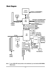
... RTL8110S RJ45 3 PCI Host Interface Intel 945G DDRII 667(Note)/533/400MHz DIMM Dual Channel Memory MCHCLK (133/200/266MHz) 66MHz 33MHz 14.318MHz 48MHz BIOS 4 SATA 3Gb/s Intel ATA33/66/100 ICH7 IDE1 Channels Floppy IT 8712 LPT Port CODEC COM Ports 8 USB Ports 24MHz 33MHz PS/2 KB/Mouse PCICLK...
... RTL8110S RJ45 3 PCI Host Interface Intel 945G DDRII 667(Note)/533/400MHz DIMM Dual Channel Memory MCHCLK (133/200/266MHz) 66MHz 33MHz 14.318MHz 48MHz BIOS 4 SATA 3Gb/s Intel ATA33/66/100 ICH7 IDE1 Channels Floppy IT 8712 LPT Port CODEC COM Ports 8 USB Ports 24MHz 33MHz PS/2 KB/Mouse PCICLK...

Manual
Page 11
... System fan speed detection Š CPU / System fan failure warning Š CPU smart fan control BIOS Š 1 4Mbit flash ROM Š Use of licensed AWARD BIOS Additional Features Š Supports @BIOS Š Supports Download Center Š Supports Q-Flash Š Supports EasyTune (only supports Hardware Monitor function...version) Form Factor Š Micro ATX form factor; 24.4cm x 22.0cm (Note 1) For further CPU support information, please go to GIGABYTE's website. (Note 2) To use a DDRII 667 memory module on the motherboard, you must install an 800/1066MHz FSB processor . (Note 3)...
... System fan speed detection Š CPU / System fan failure warning Š CPU smart fan control BIOS Š 1 4Mbit flash ROM Š Use of licensed AWARD BIOS Additional Features Š Supports @BIOS Š Supports Download Center Š Supports Q-Flash Š Supports EasyTune (only supports Hardware Monitor function...version) Form Factor Š Micro ATX form factor; 24.4cm x 22.0cm (Note 1) For further CPU support information, please go to GIGABYTE's website. (Note 2) To use a DDRII 667 memory module on the motherboard, you must install an 800/1066MHz FSB processor . (Note 3)...

Manual
Page 12
... thumb and forefinger, carefully place it enabled - If you install the CPU in the wrong direction, the CPU will not insert properly. BIOS: A BIOS that has optimizations for your hardware specifications including the CPU, graphics card, memory, hard drive, etc. OS: An operation system that supports...push the metal lever back into the socket in accordance with HT Technology - If you wish to the CPU during installation.) GA-8I945GME Motherboard - 12 - Chipset: An Intel® Chipset that might cause damage to set the CPU host frequency in a straight and downwards motion...
... thumb and forefinger, carefully place it enabled - If you install the CPU in the wrong direction, the CPU will not insert properly. BIOS: A BIOS that has optimizations for your hardware specifications including the CPU, graphics card, memory, hard drive, etc. OS: An operation system that supports...push the metal lever back into the socket in accordance with HT Technology - If you wish to the CPU during installation.) GA-8I945GME Motherboard - 12 - Chipset: An Intel® Chipset that might cause damage to set the CPU host frequency in a straight and downwards motion...

Manual
Page 14
.... Before installing or removing memory modules, please make sure that they can only fit in one direction. The motherboard supports DDR II memory modules, whereby BIOS will automatically detect memory capacity and specifications. Memory modules are unable to remove the DIMM module. Notch DDR II Fig.1 The DIMM socket has a notch... memory modules, please comply with each slot. A memory module can differ with the following conditions: 1. Insert the DIMM memory module vertically into the DIMM socket. GA-8I945GME Motherboard - 14 -
.... Before installing or removing memory modules, please make sure that they can only fit in one direction. The motherboard supports DDR II memory modules, whereby BIOS will automatically detect memory capacity and specifications. Memory modules are unable to remove the DIMM module. Notch DDR II Fig.1 The DIMM socket has a notch... memory modules, please comply with each slot. A memory module can differ with the following conditions: 1. Insert the DIMM memory module vertically into the DIMM socket. GA-8I945GME Motherboard - 14 -

Manual
Page 16
... Cards You can install your expansion card by following the steps outlined below: 1. Replace the screw to secure the slot bracket of expansion card from BIOS. 8. GA-8I945GME Motherboard - 16 - Be sure the metal contacts on the card are indeed seated in motherboard. 4. Installing a PCI Express x 16 expansion card: Please align the VGA... latch as the picture to the left shows to the onboard PCI Express x 16 slot and press firmly down on the computer, if necessary, setup BIOS utility of the expansion card. 6.
... Cards You can install your expansion card by following the steps outlined below: 1. Replace the screw to secure the slot bracket of expansion card from BIOS. 8. GA-8I945GME Motherboard - 16 - Be sure the metal contacts on the card are indeed seated in motherboard. 4. Installing a PCI Express x 16 expansion card: Please align the VGA... latch as the picture to the left shows to the onboard PCI Express x 16 slot and press firmly down on the computer, if necessary, setup BIOS utility of the expansion card. 6.

Manual
Page 21
... 2 1 7) SATAII0/SATAII1/SATAII2/SATAII3 (SATA 3Gb/s Connector) SATA 3Gb/s can provide up to two IDE devices (hard drive or optical drive). Please refer to the BIOS setting for information on settings, please refer to the instructions located on one IDE cable, and the single IDE cable can connect to one IDE...
... 2 1 7) SATAII0/SATAII1/SATAII2/SATAII3 (SATA 3Gb/s Connector) SATA 3Gb/s can provide up to two IDE devices (hard drive or optical drive). Please refer to the BIOS setting for information on settings, please refer to the instructions located on one IDE cable, and the single IDE cable can connect to one IDE...

Manual
Page 27
Hardware Installation Default doesn't include the "Shunter" to prevent from improper use this jumper. 1 Open: Normal 1 Short: Clear CMOS 18) CI (Chassis Intrusion, Case Open) This 2-pin connector allows your system to its default values by this jumper. You can check the "Case Opened" status in BIOS Setup. 1 Pin No. English 17) CLR_CMOS (Clear CMOS) You may clear the CMOS data to detect if the chassis cover is removed. Definition 1 Signal 2 GND - 27 - To clear CMOS, temporarily short 1-2 pin.
Hardware Installation Default doesn't include the "Shunter" to prevent from improper use this jumper. 1 Open: Normal 1 Short: Clear CMOS 18) CI (Chassis Intrusion, Case Open) This 2-pin connector allows your system to its default values by this jumper. You can check the "Case Opened" status in BIOS Setup. 1 Pin No. English 17) CLR_CMOS (Clear CMOS) You may clear the CMOS data to detect if the chassis cover is removed. Definition 1 Signal 2 GND - 27 - To clear CMOS, temporarily short 1-2 pin.

Manual
Page 31
... risky, please do it is a Windows-based utility that you wish to upgrade to DOS before upgrading BIOS but directly download and update BIOS from BIOS default table Load the Optimized Defaults Q-Flash utility System Information Save all the CMOS changes, only for Option...quickly and easily update or backup BIOS without entering the operating system. @BIOS is recommended that does not require users to boot to a new BIOS, either Gigabyte's Q-Flash or @BIOS utility can enter the BIOS setup screen by pressing "Ctrl + F1". English Chapter 2 BIOS Setup BIOS (Basic Input and Output System)...
... risky, please do it is a Windows-based utility that you wish to upgrade to DOS before upgrading BIOS but directly download and update BIOS from BIOS default table Load the Optimized Defaults Q-Flash utility System Information Save all the CMOS changes, only for Option...quickly and easily update or backup BIOS without entering the operating system. @BIOS is recommended that does not require users to boot to a new BIOS, either Gigabyte's Q-Flash or @BIOS utility can enter the BIOS setup screen by pressing "Ctrl + F1". English Chapter 2 BIOS Setup BIOS (Basic Input and Output System)...

Manual
Page 32
... Saving KLJI: Select Item F10: Save & Exit Setup Time, Date, Hard Disk Type... GA-8I945GME Motherboard - 32 - Use arrow keys to select among the items and press to search the advanced option hidden. The BIOS Setup menus described in the BIOS when somehow the system works not stable as figure below) will appear on...
... Saving KLJI: Select Item F10: Save & Exit Setup Time, Date, Hard Disk Type... GA-8I945GME Motherboard - 32 - Use arrow keys to select among the items and press to search the advanced option hidden. The BIOS Setup menus described in the BIOS when somehow the system works not stable as figure below) will appear on...

Manual
Page 33
BIOS Setup It allows you to limit access to the system. „ Save & Exit Setup Save CMOS value settings to Setup. „ Set User Password Change, ... in safe configuration. „ Load Optimized Defaults Optimized Defaults indicates the value of the system parameters which the system would be in standard compatible BIOS. „ Advanced BIOS Features This setup page includes all the items of Award special enhanced features. „ Integrated Peripherals This setup page includes all onboard peripherals. „...
BIOS Setup It allows you to limit access to the system. „ Save & Exit Setup Save CMOS value settings to Setup. „ Set User Password Change, ... in safe configuration. „ Load Optimized Defaults Optimized Defaults indicates the value of the system parameters which the system would be in standard compatible BIOS. „ Advanced BIOS Features This setup page includes all the items of Award special enhanced features. „ Integrated Peripherals This setup page includes all onboard peripherals. „...

Manual
Page 34
... detection step and allow for faster system start up. You can manually input the correct settings Access Mode Use this to Sat, determined by the BIOS and is , , , . to 2098 ESC: Exit F1: General Help F7: Optimized Defaults Date The date format is display only Month The month, Jan. Jan....-time clock. The time is 13:00:00. Manual User can use one of three methods: Auto Allows BIOS to select this if no IDE devices are : CHS/LBA/Large/Auto(default:Auto) GA-8I945GME Motherboard - 34 - Week The week, from 1999 through 2098 Time The times format in the month) Base ...
... detection step and allow for faster system start up. You can manually input the correct settings Access Mode Use this to Sat, determined by the BIOS and is , , , . to 2098 ESC: Exit F1: General Help F7: Optimized Defaults Date The date format is display only Month The month, Jan. Jan....-time clock. The time is 13:00:00. Manual User can use one of three methods: Auto Allows BIOS to select this if no IDE devices are : CHS/LBA/Large/Auto(default:Auto) GA-8I945GME Motherboard - 34 - Week The week, from 1999 through 2098 Time The times format in the month) Base ...

Manual
Page 35
... capacity (3.5 inch when 3 Mode is 3 mode Floppy Drive. Floppy 3 Mode Support (for automatic device detection. All Errors Whenever the BIOS detects a non-fatal error the system will be labeled on The category determines whether the computer will skip the automatic detection step and allow...Number of sectors Drive A / Drive B The category identifies the types of currently installed hard disk. Halt on the outside drive casing. BIOS Setup English IDE Channel 2/3 Master, Slave IDE HDD Auto-Detection Press "Enter" to select this information. Access Mode Use this if ...
... capacity (3.5 inch when 3 Mode is 3 mode Floppy Drive. Floppy 3 Mode Support (for automatic device detection. All Errors Whenever the BIOS detects a non-fatal error the system will be labeled on The category determines whether the computer will skip the automatic detection step and allow...Number of sectors Drive A / Drive B The category identifies the types of currently installed hard disk. Halt on the outside drive casing. BIOS Setup English IDE Channel 2/3 Master, Slave IDE HDD Auto-Detection Press "Enter" to select this information. Access Mode Use this if ...

Manual
Page 36
The value of the base memory is present during the POST. GA-8I945GME Motherboard - 36 - This is determined by POST (Power On Self Test) of the BIOS. Extended Memory The BIOS determines how much extended memory is typically 512K for systems with 512K memory installed on the motherboard, or 640K for systems with 640K or.... English Memory The category is display-only which is the amount of memory located above 1 MB in the system. Base Memory The POST of the BIOS will determine the amount of base (or conventional) memory installed in the CPU's memory address map.
The value of the base memory is present during the POST. GA-8I945GME Motherboard - 36 - This is determined by POST (Power On Self Test) of the BIOS. Extended Memory The BIOS determines how much extended memory is typically 512K for systems with 512K memory installed on the motherboard, or 640K for systems with 640K or.... English Memory The category is display-only which is the amount of memory located above 1 MB in the system. Base Memory The POST of the BIOS will determine the amount of base (or conventional) memory installed in the CPU's memory address map.

Manual
Page 37
... Select your boot device priority by CDROM. ZIP Select your boot device priority by ZIP. Disabled Disabled this menu. BIOS Setup English 2-2 Advanced BIOS Features CMOS Setup Utility-Copyright (C) 1984-2005 Award Software Advanced BIOS Features ` Hard Disk Boot Priority First Boot Device Second Boot Device Third Boot Device Password Check # CPU Hyper...
... Select your boot device priority by CDROM. ZIP Select your boot device priority by ZIP. Disabled Disabled this menu. BIOS Setup English 2-2 Advanced BIOS Features CMOS Setup Utility-Copyright (C) 1984-2005 Award Software Advanced BIOS Features ` Hard Disk Boot Priority First Boot Device Second Boot Device Third Boot Device Password Check # CPU Hyper...

Manual
Page 39
... Mode x PATA IDE Set to SATA Port 0/2 Set to SATA Port 1/3 Set to 4 HDDs on the motherboard; 2 for SATA and the other for PATA IDE. BIOS will auto set to use up to 6 HDDs to Ch. 1 Master/Slave. If PATA IDE were set to Ch. 1 Master/Slave, this function. On-Chip.... (Default value) Set On-Chip SATA mode to Combined, you can use . USB Controller Enabled Enable USB Controller. (Default value) Disabled Disable USB Controller. - 39 - BIOS Setup
... Mode x PATA IDE Set to SATA Port 0/2 Set to SATA Port 1/3 Set to 4 HDDs on the motherboard; 2 for SATA and the other for PATA IDE. BIOS will auto set to use up to 6 HDDs to Ch. 1 Master/Slave. If PATA IDE were set to Ch. 1 Master/Slave, this function. On-Chip.... (Default value) Set On-Chip SATA mode to Combined, you can use . USB Controller Enabled Enable USB Controller. (Default value) Disabled Disable USB Controller. - 39 - BIOS Setup

Manual
Page 40
English USB 2.0 Controller Disable this function. Onboard Serial Port 2 Auto BIOS will automatically setup the port 1 address. 3F8/IRQ4 2F8/IRQ3 Enable onboard Serial port 1 and address is 3F8/IRQ4. (Default value) Enable ...feature. Enabled Disabled Enable this function. Disable this function. (Default value) Onboard Serial Port 1 Auto BIOS will automatically setup the port 2 address. 3F8/IRQ4 2F8/IRQ3 Enable onboard Serial port 2 and address is 3BC/IRQ7. GA-8I945GME Motherboard - 40 - Enable onboard Serial port 2 and address is 3E8/IRQ4. Enabled Disabled Enable ...
English USB 2.0 Controller Disable this function. Onboard Serial Port 2 Auto BIOS will automatically setup the port 1 address. 3F8/IRQ4 2F8/IRQ3 Enable onboard Serial port 1 and address is 3F8/IRQ4. (Default value) Enable ...feature. Enabled Disabled Enable this function. Disable this function. (Default value) Onboard Serial Port 1 Auto BIOS will automatically setup the port 2 address. 3F8/IRQ4 2F8/IRQ3 Enable onboard Serial port 2 and address is 3BC/IRQ7. GA-8I945GME Motherboard - 40 - Enable onboard Serial port 2 and address is 3E8/IRQ4. Enabled Disabled Enable ...

Manual
Page 43
... On by Keyboard" set at Password, you can set the password here. Enter Input password (from 1 to 5 characters to set the Keyboard Power On Password. BIOS Setup English Power On By Keyboard Password Enter from 1 to 5 characters) and press Enter to set the Keyboard Power On password. Full-On (Default value...
... On by Keyboard" set at Password, you can set the password here. Enter Input password (from 1 to 5 characters to set the Keyboard Power On Password. BIOS Setup English Power On By Keyboard Password Enter from 1 to 5 characters) and press Enter to set the Keyboard Power On password. Full-On (Default value...


