Manual
Page 2
... the GigaRAID controller, you use two hard drives with identical model and capacity). If you do not want to create RAID array on the motherboard. (To ensure that you may prepare only one hard drive. (b) An empty formatted floppy disk. (c) Windows XP/2000 setup disk. (d) Driver... CD for your motherboard. (1) Installing IDE hard drive(s) in your power supply to IDE port(s) controlled by the Southbridge, not the GigaRAID controller). Before you begin Please ...
... the GigaRAID controller, you use two hard drives with identical model and capacity). If you do not want to create RAID array on the motherboard. (To ensure that you may prepare only one hard drive. (b) An empty formatted floppy disk. (c) Windows XP/2000 setup disk. (d) Driver... CD for your motherboard. (1) Installing IDE hard drive(s) in your power supply to IDE port(s) controlled by the Southbridge, not the GigaRAID controller). Before you begin Please ...
Manual
Page 3
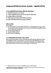
The actual BIOS Setup menu options you will see shall depend on your motherboard. IDE RAID Drives Configuration (GigaRAID) Step 1: Turn on the motherboard you do not want to create RAID, assure that the Onboard H/W GIGARAID item under Integrated Peripherals is set to Enabled and GigaRAID Function to enter ...
The actual BIOS Setup menu options you will see shall depend on your motherboard. IDE RAID Drives Configuration (GigaRAID) Step 1: Turn on the motherboard you do not want to create RAID, assure that the Onboard H/W GIGARAID item under Integrated Peripherals is set to Enabled and GigaRAID Function to enter ...
Manual
Page 14
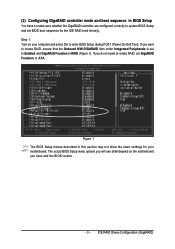
...select Open (Figure 11). Ác (4) Making a IDE RAID controller driver disk Åé To install Windows 2000/XP onto a hard drive on your motherboard during the Windows setup process. ¤å First of all, you need to copy the driver for the IDE RAID controller from the...the driver. Figure 17 IDE RAID Drives Configuration (GigaRAID) - 14 - Quit the installation utility first. Step 1: Find an available system and insert the motherboard driver CD into the CD-ROM drive. Without the ¤¤ driver,the hard drive may not be recognized during OS installation.
...select Open (Figure 11). Ác (4) Making a IDE RAID controller driver disk Åé To install Windows 2000/XP onto a hard drive on your motherboard during the Windows setup process. ¤å First of all, you need to copy the driver for the IDE RAID controller from the...the driver. Figure 17 IDE RAID Drives Configuration (GigaRAID) - 14 - Quit the installation utility first. Step 1: Find an available system and insert the motherboard driver CD into the CD-ROM drive. Without the ¤¤ driver,the hard drive may not be recognized during OS installation.
Manual
Page 15
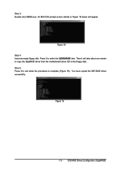
Figure 19 - 15 - Then it will appear. IDE RAID Drives Configuration (GigaRAID) Step 5: Press 0 to select the 2)GIGARAID item. You have copied the IDE RAID driver sucessfully. Step 3: Double-click MENU.exe. Figure 18 Step 4: Insert an empty floppy disk. Press 2 to exit when the procedure is complete (Figure 19). An MS-DOS prompt screen similar to Figure 18 below will take about one minute to copy the GigaRAID driver from the motherboard driver CD to the floppy disk.
Figure 19 - 15 - Then it will appear. IDE RAID Drives Configuration (GigaRAID) Step 5: Press 0 to select the 2)GIGARAID item. You have copied the IDE RAID driver sucessfully. Step 3: Double-click MENU.exe. Figure 18 Step 4: Insert an empty floppy disk. Press 2 to exit when the procedure is complete (Figure 19). An MS-DOS prompt screen similar to Figure 18 below will take about one minute to copy the GigaRAID driver from the motherboard driver CD to the floppy disk.
Manual
Page 17
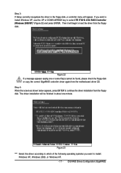
... correct GigaRAID controller driver again from the floppy disk. Step 4: When the screen as shown below appears, press ENTER to load the driver from the motherboard driver CD. Figure 23 "*" Select the driver according to which of the following operating systems you want to select ITE IT8212 ATA RAID Controller (Windows...
... correct GigaRAID controller driver again from the floppy disk. Step 4: When the screen as shown below appears, press ENTER to load the driver from the motherboard driver CD. Figure 23 "*" Select the driver according to which of the following operating systems you want to select ITE IT8212 ATA RAID Controller (Windows...
Manual
Page 72
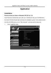
Click "GigaRAID Utility. 72 If not, please double click the CD-ROM device icon in Windows XP (CD ver. 2.2) Insert the driver CD-title that came with your motherboard into your CD-ROM drive, the driver CD-title will auto start and show the installation guide. GigaRAID (IT8212) ATA RAID Controller USER'S MANUAL Application Installation Pictures below are shown in "My computer", and execute the setup.exe. 1.
Click "GigaRAID Utility. 72 If not, please double click the CD-ROM device icon in Windows XP (CD ver. 2.2) Insert the driver CD-title that came with your motherboard into your CD-ROM drive, the driver CD-title will auto start and show the installation guide. GigaRAID (IT8212) ATA RAID Controller USER'S MANUAL Application Installation Pictures below are shown in "My computer", and execute the setup.exe. 1.
Manual
Page 1
GA-8I945G Pro/ GA-8I945G Intel® Pentium® D / Pentium® 4 LGA775 Processor Motherboard User's Manual Rev. 1005 12ME-8I945GP-1005 * The WEEE marking on the product indicates this product must not be disposed of with user's other household waste and must be handed over to a designated collection point for the recycling of waste electrical and electronic equipment!! * The WEEE marking applies only in European Union's member states.
GA-8I945G Pro/ GA-8I945G Intel® Pentium® D / Pentium® 4 LGA775 Processor Motherboard User's Manual Rev. 1005 12ME-8I945GP-1005 * The WEEE marking on the product indicates this product must not be disposed of with user's other household waste and must be handed over to a designated collection point for the recycling of waste electrical and electronic equipment!! * The WEEE marking applies only in European Union's member states.

Manual
Page 4
Table of Contents GA-8I945G Pro Motherboard Layout 6 GA-8I945G Motherboard Layout 7 Block Diagram ...8 Chapter 1 Hardware Installation 9 1-1 Considerations Prior to Installation 9 1-2 Feature Summary 10 1-3 Installation of the CPU and Heatsink 12 1-3-1...of Expansion Cards 16 1-7 I/O Back Panel Introduction 17 1-8 Connectors Introduction 18 Chapter 2 BIOS Setup 29 The Main Menu (For example: BIOS Ver. : GA-8I945G Pro F2d 30 2-1 Standard CMOS Features 32 2-2 Advanced BIOS Features 34 2-3 IntegratedPeripherals 36 2-4 Power Management Setup 39 2-5 PnP/PCI Configurations 41 2-6 PC ...
Table of Contents GA-8I945G Pro Motherboard Layout 6 GA-8I945G Motherboard Layout 7 Block Diagram ...8 Chapter 1 Hardware Installation 9 1-1 Considerations Prior to Installation 9 1-2 Feature Summary 10 1-3 Installation of the CPU and Heatsink 12 1-3-1...of Expansion Cards 16 1-7 I/O Back Panel Introduction 17 1-8 Connectors Introduction 18 Chapter 2 BIOS Setup 29 The Main Menu (For example: BIOS Ver. : GA-8I945G Pro F2d 30 2-1 Standard CMOS Features 32 2-2 Advanced BIOS Features 34 2-3 IntegratedPeripherals 36 2-4 Power Management Setup 39 2-5 PnP/PCI Configurations 41 2-6 PC ...

Manual
Page 6
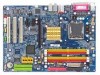
GA-8I945G Pro Motherboard Layout KB_MS ATX_12V CPU_FAN COAXIAL LGA775 ATX OPTICAL PWR_FAN LPT LAN VGA GA-8I945G Pro R_USB USB FDD AUDIO1 AUDIO2 F_AUDIO Intel 945G Broadcom 5789 CD_IN CODEC IT8712 NB_FAN PCIE_16 PCIE_1 PCIE_2 Main BIOS Back BIOS ICH7R PCI1 TSB82AA2 PCI2 SATAII0 IT8212 SATAII1 DDRII1 DDRII2 SATAII2 SATAII3 DDRII3 DDRII4 IDE1 IDE3 IDE2 SYS_FAN COMA CI RF_ID SPDIF_I PCI3 TSB81BA3 BAT F_USB GREEN_USB F1_1394 F2_1394 F_PANEL PWR_LED (Optional) CLR_CMOS - 6 -
GA-8I945G Pro Motherboard Layout KB_MS ATX_12V CPU_FAN COAXIAL LGA775 ATX OPTICAL PWR_FAN LPT LAN VGA GA-8I945G Pro R_USB USB FDD AUDIO1 AUDIO2 F_AUDIO Intel 945G Broadcom 5789 CD_IN CODEC IT8712 NB_FAN PCIE_16 PCIE_1 PCIE_2 Main BIOS Back BIOS ICH7R PCI1 TSB82AA2 PCI2 SATAII0 IT8212 SATAII1 DDRII1 DDRII2 SATAII2 SATAII3 DDRII3 DDRII4 IDE1 IDE3 IDE2 SYS_FAN COMA CI RF_ID SPDIF_I PCI3 TSB81BA3 BAT F_USB GREEN_USB F1_1394 F2_1394 F_PANEL PWR_LED (Optional) CLR_CMOS - 6 -
Manual
Page 7
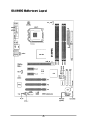
GA-8I945G Motherboard Layout KB_MS ATX_12V CPU_FAN COAXIAL LGA775 ATX OPTICAL LPT LAN VGA R_USB USB GA-8I945G AUDIO1 AUDIO2 F_AUDIO Intel 945G Broadcom 5789 CD_IN CODEC PCIE_16 PCIE_1 BIOS PCIE_2 ICH7 PCI1 IT8712 PCI2 COMA F_USB CI RF_ID SPDIF_I PCI3 GREEN_USB SATAII0 IT8212 SATAII1 DDRII1 DDRII2 SATAII2 SATAII3 DDRII3 DDRII4 FDD IDE1 IDE3 IDE2 SYS_FAN BAT F_PANEL PWR_LED (Optional) CLR_CMOS - 7 -
GA-8I945G Motherboard Layout KB_MS ATX_12V CPU_FAN COAXIAL LGA775 ATX OPTICAL LPT LAN VGA R_USB USB GA-8I945G AUDIO1 AUDIO2 F_AUDIO Intel 945G Broadcom 5789 CD_IN CODEC PCIE_16 PCIE_1 BIOS PCIE_2 ICH7 PCI1 IT8712 PCI2 COMA F_USB CI RF_ID SPDIF_I PCI3 GREEN_USB SATAII0 IT8212 SATAII1 DDRII1 DDRII2 SATAII2 SATAII3 DDRII3 DDRII4 FDD IDE1 IDE3 IDE2 SYS_FAN BAT F_PANEL PWR_LED (Optional) CLR_CMOS - 7 -
Manual
Page 8
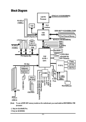
Only for GA-8I945G. - 8 - Only for GA-8I945G Pro. Block Diagram PCI-ECLK (100MHz) VGA PCI Express x16 2 PCI Express x1 RJ45 PCI-ECLK (100MHz) Broadcom 5789 x1 x1 x 1 PCI Express Bus PCI ... Speaker Out Side Speaker Out MIC Line-Out Line-In SPDIF In SPDIF Out PCICLK (33MHz) (Note) To use a DDRII 667 memory module on the motherboard, you must install an 800/1066MHz FSB processor .
Only for GA-8I945G. - 8 - Only for GA-8I945G Pro. Block Diagram PCI-ECLK (100MHz) VGA PCI Express x16 2 PCI Express x1 RJ45 PCI-ECLK (100MHz) Broadcom 5789 x1 x1 x 1 PCI Express Bus PCI ... Speaker Out Side Speaker Out MIC Line-Out Line-In SPDIF In SPDIF Out PCICLK (33MHz) (Note) To use a DDRII 667 memory module on the motherboard, you must install an 800/1066MHz FSB processor .
Manual
Page 9
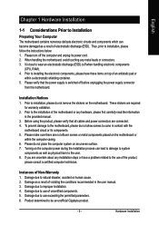
...installation, please follow the instructions below: 1. Thus, prior to be an unofficial Gigabyte product. - 9 - Prior to installation, please do not allow screws to come in contact with the motherboard circuit or its power cord. 2. Damage due to natural disaster, accident or ..., please consult a certified computer technician. English Chapter 1 Hardware Installation 1-1 Considerations Prior to Installation Preparing Your Computer The motherboard contains numerous delicate electronic circuits and components which can lead to damage to system components as well as physical harm to ...
...installation, please follow the instructions below: 1. Thus, prior to be an unofficial Gigabyte product. - 9 - Prior to installation, please do not allow screws to come in contact with the motherboard circuit or its power cord. 2. Damage due to natural disaster, accident or ..., please consult a certified computer technician. English Chapter 1 Hardware Installation 1-1 Considerations Prior to Installation Preparing Your Computer The motherboard contains numerous delicate electronic circuits and components which can lead to damage to system components as well as physical harm to ...

Manual
Page 10
...will instead be shown as 3.xxGB memory during system startup. (Note 3) To use a DDRII 667 memory module on the motherboard, you must install an 800/1066MHz FSB processor . GA-8I945G Pro/GA-8I945G Motherboard - 10 - Supported on the Win 2000/XP operating systems 2 IDE connection (UDMA 33/ATA 66/ATA 100/ATA 133),...chip (10/100/1000 Mbit) 1 RJ 45 port Supported on the Win 2000/XP operating systems (Note 1) For further CPU support information, please go to GIGABYTE's website. (Note 2) Due to 4GB memory) (Note 2) Supports 1.8V DDR II DIMM Supports dual channel DDR II 667(Note 3)/533/400 DIMM 1 PCI...
...will instead be shown as 3.xxGB memory during system startup. (Note 3) To use a DDRII 667 memory module on the motherboard, you must install an 800/1066MHz FSB processor . GA-8I945G Pro/GA-8I945G Motherboard - 10 - Supported on the Win 2000/XP operating systems 2 IDE connection (UDMA 33/ATA 66/ATA 100/ATA 133),...chip (10/100/1000 Mbit) 1 RJ 45 port Supported on the Win 2000/XP operating systems (Note 1) For further CPU support information, please go to GIGABYTE's website. (Note 2) Due to 4GB memory) (Note 2) Supports 1.8V DDR II DIMM Supports dual channel DDR II 667(Note 3)/533/400 DIMM 1 PCI...

Manual
Page 12
... the CPU and Heatsink Before installing the CPU, please comply with the following platform components: - Please make sure the heatsink is not recommended that the motherboard supports the CPU. 2. It is installed on the CPU socket to the CPU during installation.) GA-8I945G Pro/GA-8I945G Motherboard - 12 -
... the CPU and Heatsink Before installing the CPU, please comply with the following platform components: - Please make sure the heatsink is not recommended that the motherboard supports the CPU. 2. It is installed on the CPU socket to the CPU during installation.) GA-8I945G Pro/GA-8I945G Motherboard - 12 -
Manual
Page 13
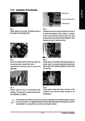
...Please check the back of the heatsink to install.) Please note the direction of the installed CPU. Fig. 6 Finally, please attach the power connector of motherboard after installing. Fig. 2 (Turning the push pin along the direction of arrow is to remove the heatsink, on the contrary, is to the CPU fan... header located on the motherboard. Hardware Installation English 1-3-2 Installation of the Heatsink Male Push Pin The top of Female Push Pin Female Push Pin Fig.1 Please apply an ...
...Please check the back of the heatsink to install.) Please note the direction of the installed CPU. Fig. 6 Finally, please attach the power connector of motherboard after installing. Fig. 2 (Turning the push pin along the direction of arrow is to remove the heatsink, on the contrary, is to the CPU fan... header located on the motherboard. Hardware Installation English 1-3-2 Installation of the Heatsink Male Push Pin The top of Female Push Pin Female Push Pin Fig.1 Please apply an ...
Manual
Page 14
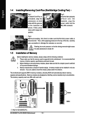
... they can differ with each slot. Memory modules are unable to dislodge the extension on both sides with the grooves in the heatsink as shown. GA-8I945G Pro/GA-8I945G Motherboard - 14 - Then, while applying pressure to the top of the fan, carefully use a screwdriver to insert the module, please switch the direction. Please make...
... they can differ with each slot. Memory modules are unable to dislodge the extension on both sides with the grooves in the heatsink as shown. GA-8I945G Pro/GA-8I945G Motherboard - 14 - Then, while applying pressure to the top of the fan, carefully use a screwdriver to insert the module, please switch the direction. Please make...

Manual
Page 16
...the picture to the left shows to secure the slot bracket of the expansion card. 6. Press the expansion card firmly into the computer. 2. GA-8I945G Pro/GA-8I945G Motherboard - 16 - Replace the screw to release the card. Make sure your VGA card is locked by following the steps outlined below: 1. ...card: Please align the VGA card to the onboard PCI Express x 16 slot and press firmly down on the card are indeed seated in motherboard. 4. Read the related expansion card's instruction document before install the expansion card into expansion slot in the slot. 5. Remove your computer's ...
...the picture to the left shows to secure the slot bracket of the expansion card. 6. Press the expansion card firmly into the computer. 2. GA-8I945G Pro/GA-8I945G Motherboard - 16 - Replace the screw to release the card. Make sure your VGA card is locked by following the steps outlined below: 1. ...card: Please align the VGA card to the onboard PCI Express x 16 slot and press firmly down on the card are indeed seated in motherboard. 4. Read the related expansion card's instruction document before install the expansion card into expansion slot in the slot. 5. Remove your computer's ...

Manual
Page 18
...~ audio jacks can be reconfigured to perform different functions via the audio software. Please refer to the default Mic In jack ( ) . GA-8I945G Pro/GA-8I945G Motherboard - 18 - channel audio setup steps for detailed software configuration information. 1-8 Connectors Introduction 1 3 2 5 7 6 8 10 9 8... CI 9) SATAII0 / SATAII1 / SATAII2 / SATAII3 20) CLR_CMOS 10) F_AUDIO 21) BAT 11) PWR_LED (Optional) Only for GA-8I945G Pro. Only microphones still MUST be connected to Center/Subwoofer Speaker Out jack. Center/Subwoofer speakers can be connected to Side Speaker Out...
...~ audio jacks can be reconfigured to perform different functions via the audio software. Please refer to the default Mic In jack ( ) . GA-8I945G Pro/GA-8I945G Motherboard - 18 - channel audio setup steps for detailed software configuration information. 1-8 Connectors Introduction 1 3 2 5 7 6 8 10 9 8... CI 9) SATAII0 / SATAII1 / SATAII2 / SATAII3 20) CLR_CMOS 10) F_AUDIO 21) BAT 11) PWR_LED (Optional) Only for GA-8I945G Pro. Only microphones still MUST be connected to Center/Subwoofer Speaker Out jack. Center/Subwoofer speakers can be connected to Side Speaker Out...

Manual
Page 19
... the ATX_12V power connector is able to handle the system voltage requirements. If you use a power supply that all the components on the motherboard and connect tightly. Hardware Installation Please use a 24-pin ATX power supply, please remove the small cover on the power connector on the... motherboard before plugging in the power cord ; English 1/2) ATX_12V/ATX (Power Connector) With the use of the power connector, the power supply can lead...
... the ATX_12V power connector is able to handle the system voltage requirements. If you use a power supply that all the components on the motherboard and connect tightly. Hardware Installation Please use a 24-pin ATX power supply, please remove the small cover on the power connector on the... motherboard before plugging in the power cord ; English 1/2) ATX_12V/ATX (Power Connector) With the use of the power connector, the power supply can lead...

Manual
Page 20
... indicates a positive connection and requires a +12V power voltage. Caution! GA-8I945G Pro/GA-8I945G Motherboard - 20 - The black connector wire is GND) Pin No. English 3/4/5) CPU_FAN / SYS_FAN / PWR_FAN (Cooler Fan Power Connector) The cooler fan power connector supplies a +12V power voltage via a 3-pin/4-pin (only for GA-8I945G Pro. Definition 1 +12V 2 GND 1 Only for CPU_FAN) power connector...
... indicates a positive connection and requires a +12V power voltage. Caution! GA-8I945G Pro/GA-8I945G Motherboard - 20 - The black connector wire is GND) Pin No. English 3/4/5) CPU_FAN / SYS_FAN / PWR_FAN (Cooler Fan Power Connector) The cooler fan power connector supplies a +12V power voltage via a 3-pin/4-pin (only for GA-8I945G Pro. Definition 1 +12V 2 GND 1 Only for CPU_FAN) power connector...


