Manual
Page 1
GA-8I915P-MF Intel® Pentium® 4 LGA775 Processor Motherboard User's Manual Rev. 2202 12ME-8I915PMF-2202 * The WEEE marking on the product indicates this product must not be disposed of with user's other household waste and must be handed over to a designated collection point for the recycling of waste electrical and electronic equipment!! * The WEEE marking applies only in European Union's member states.
GA-8I915P-MF Intel® Pentium® 4 LGA775 Processor Motherboard User's Manual Rev. 2202 12ME-8I915PMF-2202 * The WEEE marking on the product indicates this product must not be disposed of with user's other household waste and must be handed over to a designated collection point for the recycling of waste electrical and electronic equipment!! * The WEEE marking applies only in European Union's member states.

Manual
Page 2
Motherboard GA-8I915P-MF Jun. 11, 2004 Motherboard GA-8I915P-MF Jun. 11, 2004
Motherboard GA-8I915P-MF Jun. 11, 2004 Motherboard GA-8I915P-MF Jun. 11, 2004
Manual
Page 4
Table of Content GA-8I915P-MF Motherboard Layout 6 Block Diagram ...7 Chapter 1 Hardware Installation 9 1-1 Considerations Prior to Installation 9 1-2 Feature Summary 10 1-3 Installation of the CPU and Heatsink 12 1-3-1 Installation of the CPU 12 1-3-2 ...
Table of Content GA-8I915P-MF Motherboard Layout 6 Block Diagram ...7 Chapter 1 Hardware Installation 9 1-1 Considerations Prior to Installation 9 1-2 Feature Summary 10 1-3 Installation of the CPU and Heatsink 12 1-3-1 Installation of the CPU 12 1-3-2 ...

Manual
Page 6
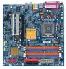
GA-8I915P-MF Motherboard Layout IT8712 KB_MS SPDIF_O SPDIF_I CPU_FAN SYS_FAN IR ATX COMA LPT R_USB ATX_12V LGA775 GA-8I915P-MF DDR1 DDR2 USB LAN AZALIA_FP AUDIO1 AUDIO2 PCIE_16 RTL8110S CD_IN CODEC PCIE_1 COMB Intel 915P IDE FDD DDR3 DDR4 PCI1 PCI2 ICH6 TSB43AB23 F2_1394 F1_1394 F_USB1 F_USB2 BAT S_ATA3 S_ATA2 S_ATA1 S_ATA0 BIOS CLR_CMOS PWR_LED F_PANEL - 6 -
GA-8I915P-MF Motherboard Layout IT8712 KB_MS SPDIF_O SPDIF_I CPU_FAN SYS_FAN IR ATX COMA LPT R_USB ATX_12V LGA775 GA-8I915P-MF DDR1 DDR2 USB LAN AZALIA_FP AUDIO1 AUDIO2 PCIE_16 RTL8110S CD_IN CODEC PCIE_1 COMB Intel 915P IDE FDD DDR3 DDR4 PCI1 PCI2 ICH6 TSB43AB23 F2_1394 F1_1394 F_USB1 F_USB2 BAT S_ATA3 S_ATA2 S_ATA1 S_ATA0 BIOS CLR_CMOS PWR_LED F_PANEL - 6 -

Manual
Page 9
... Installation Please do not remove the stickers on an uneven surface. 7. When handling the motherboard, avoid touching any installation steps or have these items on the motherboard or within a electrostatic shielding container. 5. Damage due to be an unofficial Gigabyte product. - 9 - Installation Notices 1. Prior to wear an electrostatic discharge (ESD) cuff when handling electronic...
... Installation Please do not remove the stickers on an uneven surface. 7. When handling the motherboard, avoid touching any installation steps or have these items on the motherboard or within a electrostatic shielding container. 5. Damage due to be an unofficial Gigabyte product. - 9 - Installation Notices 1. Prior to wear an electrostatic discharge (ESD) cuff when handling electronic...
Manual
Page 10
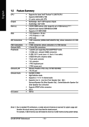
... CODEC Š High Definition Audio Š Supports 2 / 4 / 6 / 8 channel audio Š Supports Line In ; MIC ; Line Out (Front Speaker Out) ; Surround Speaker Out (Rear Speaker Out) ; GA-8I915P-MF Motherboard - 10 - For example, 4 GB of memory is reserved for system usage and therefore the actual memory size is less than the stated amount. English 1-2 Feature...
... CODEC Š High Definition Audio Š Supports 2 / 4 / 6 / 8 channel audio Š Supports Line In ; MIC ; Line Out (Front Speaker Out) ; Surround Speaker Out (Rear Speaker Out) ; GA-8I915P-MF Motherboard - 10 - For example, 4 GB of memory is reserved for system usage and therefore the actual memory size is less than the stated amount. English 1-2 Feature...

Manual
Page 12
...CPU firmly between the CPU and heatsink. 4. If you wish to set beyond the proper specifications, please do so according to the CPU during installation.) GA-8I915P-MF Motherboard - 12 - Please make sure that supports HT Technology and has it into the socket in a straight and downwards motion. Avoid twisting or bending motions... CPU, please comply with the following platform components: - If you install the CPU in accordance with the processor specifications. BIOS: A BIOS that the motherboard supports the CPU. 2. Align the indented corner of the CPU with HT Technology -
...CPU firmly between the CPU and heatsink. 4. If you wish to set beyond the proper specifications, please do so according to the CPU during installation.) GA-8I915P-MF Motherboard - 12 - Please make sure that supports HT Technology and has it into the socket in a straight and downwards motion. Avoid twisting or bending motions... CPU, please comply with the following platform components: - If you install the CPU in accordance with the processor specifications. BIOS: A BIOS that the motherboard supports the CPU. 2. Align the indented corner of the CPU with HT Technology -

Manual
Page 13
... the Heatsink Male Push Pin The top of Female Push Pin Female Push Pin Fig.1 Please apply an even layer of heatsink paste on the motherboard. Fig. 2 (Turning the push pin along the direction of arrow is to remove the heatsink, on the contrary, is to install.)Please ...sink paste be used for detailed installation instructions, please refer to the pin hole on the motherboard.Pressing down the push pins diagonally. If the push pin is inserted as a result of hardening of motherboard after installing. Fig. 4 Please make sure the push pins aim to the heatsink installation ...
... the Heatsink Male Push Pin The top of Female Push Pin Female Push Pin Fig.1 Please apply an even layer of heatsink paste on the motherboard. Fig. 2 (Turning the push pin along the direction of arrow is to remove the heatsink, on the contrary, is to install.)Please ...sink paste be used for detailed installation instructions, please refer to the pin hole on the motherboard.Pressing down the push pins diagonally. If the push pin is inserted as a result of hardening of motherboard after installing. Fig. 4 Please make sure the push pins aim to the heatsink installation ...
Manual
Page 14
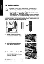
...installing or removing memory modules, please make sure that the computer power is supported by the motherboard. The memory capacity used can be installed in only one direction. 2. Close the plastic ...Please make sure that the memory used . 2. It is recommended that they can only fit in one direction. The motherboard supports DDR memory modules, whereby BIOS will automatically detect memory capacity and specifications. The DIMM slot has a notch, so ... 3. Insert the DIMM memory module vertically into the DIMM slot. Then push it down. 3. GA-8I915P-MF Motherboard - 14 -
...installing or removing memory modules, please make sure that the computer power is supported by the motherboard. The memory capacity used can be installed in only one direction. 2. Close the plastic ...Please make sure that the memory used . 2. It is recommended that they can only fit in one direction. The motherboard supports DDR memory modules, whereby BIOS will automatically detect memory capacity and specifications. The DIMM slot has a notch, so ... 3. Insert the DIMM memory module vertically into the DIMM slot. Then push it down. 3. GA-8I915P-MF Motherboard - 14 -

Manual
Page 16
...cover. 7. Replace the screw to the onboard PCI Express x 16 slot and press firmly down on the card are indeed seated in motherboard. 4. Install related driver from the computer. 3. Installing a PCI Express x 16 expansion card: Please carefully pull out the small whitedrawable ...into the computer. 2. Read the related expansion card's instruction document before install the expansion card into expansion slot in the slot. 5. GA-8I915P-MF Motherboard - 16 - Replace your computer's chassis cover, screws and slot bracket from the operating system. Be sure the metal contacts on the...
...cover. 7. Replace the screw to the onboard PCI Express x 16 slot and press firmly down on the card are indeed seated in motherboard. 4. Install related driver from the computer. 3. Installing a PCI Express x 16 expansion card: Please carefully pull out the small whitedrawable ...into the computer. 2. Read the related expansion card's instruction document before install the expansion card into expansion slot in the slot. 5. GA-8I915P-MF Motherboard - 16 - Replace your computer's chassis cover, screws and slot bracket from the operating system. Be sure the metal contacts on the...

Manual
Page 18
...) CD_IN 3) CPU_FAN 12) F_USB1 / F_USB2 4) SYS_FAN 13) F1_1394 / F2_1394 5) FDD 14) IR 6) IDE 15) COMB 7) S_ATA0 / S_ATA1 / S_ATA2 / S_ATA3 16) CLR_CMOS 8) F_PANEL 17) BAT 9) PWR_LED GA-8I915P-MF Motherboard - 18 - English Center/Subwoofer Speaker Out Connect the Center/Subwoofer speakers to this connector.
...) CD_IN 3) CPU_FAN 12) F_USB1 / F_USB2 4) SYS_FAN 13) F1_1394 / F2_1394 5) FDD 14) IR 6) IDE 15) COMB 7) S_ATA0 / S_ATA1 / S_ATA2 / S_ATA3 16) CLR_CMOS 8) F_PANEL 17) BAT 9) PWR_LED GA-8I915P-MF Motherboard - 18 - English Center/Subwoofer Speaker Out Connect the Center/Subwoofer speakers to this connector.

Manual
Page 19
If you use a 24-pin ATX power supply, please remove the small cover on the power connector on the motherboard and connect tightly. If a power supply is used that does not provide the required power, the result can withstand high power consumption be used (300W ...or greater). Align the power connector with its proper location on the motherboard before plugging in the power cord ; Please use of the power connector, the power supply can supply enough stable power to all components and devices...
If you use a 24-pin ATX power supply, please remove the small cover on the power connector on the motherboard and connect tightly. If a power supply is used that does not provide the required power, the result can withstand high power consumption be used (300W ...or greater). Align the power connector with its proper location on the motherboard before plugging in the power cord ; Please use of the power connector, the power supply can supply enough stable power to all components and devices...

Manual
Page 20
... end of FDD drives supported are designed with color-coded power connector wires. The types of the cable connects to the pin1 position. 34 33 GA-8I915P-MF Motherboard 2 1 - 20 - Please remember to connect the power to the cooler to prevent system overheating and failure. English 3/4) CPU_FAN / SYS_FAN (Cooler Fan Power Connector) The cooler...
... end of FDD drives supported are designed with color-coded power connector wires. The types of the cable connects to the pin1 position. 34 33 GA-8I915P-MF Motherboard 2 1 - 20 - Please remember to connect the power to the cooler to prevent system overheating and failure. English 3/4) CPU_FAN / SYS_FAN (Cooler Fan Power Connector) The cooler...

Manual
Page 22
Pin 3: NC Pin 4: Data(-) Open: Normal Operation Close: Reset Hardware System Open: Normal Operation Close: Power On/Off Pin 1: LED anode(+) Pin 2: LED cathode(-) NC GA-8I915P-MF Motherboard - 22 - SPEAK+ PWPW+ MSGMSG+ 2 20 1 19 NCRES+ RES- HDHD+ HD (IDE Hard Disk Active LED) SPEAK (Speaker Connector) RES (Reset Switch) PW (Power Switch) MSG(...
Pin 3: NC Pin 4: Data(-) Open: Normal Operation Close: Reset Hardware System Open: Normal Operation Close: Power On/Off Pin 1: LED anode(+) Pin 2: LED cathode(-) NC GA-8I915P-MF Motherboard - 22 - SPEAK+ PWPW+ MSGMSG+ 2 20 1 19 NCRES+ RES- HDHD+ HD (IDE Hard Disk Active LED) SPEAK (Speaker Connector) RES (Reset Switch) PW (Power Switch) MSG(...

Manual
Page 24
... out to work or even damage it. Definition 1 Power 2 Power 9 1 3 USB DX- 4 USB Dy- 10 2 5 USB DX+ 6 USB Dy+ 7 GND 8 GND 9 No Pin 10 NC GA-8I915P-MF Motherboard - 24 - Check the pin assignment carefully while you connect the front USB cable, incorrect connection between the cable and connector will make the device unable...
... out to work or even damage it. Definition 1 Power 2 Power 9 1 3 USB DX- 4 USB Dy- 10 2 5 USB DX+ 6 USB Dy+ 7 GND 8 GND 9 No Pin 10 NC GA-8I915P-MF Motherboard - 24 - Check the pin assignment carefully while you connect the front USB cable, incorrect connection between the cable and connector will make the device unable...

Manual
Page 26
... data to prevent from improper use this jumper. Default doesn't include the "Shunter" to its default values by this jumper. 1 Open: Normal 1 Short :Clear CMOS GA-8I915P-MF Motherboard - 26 - To clear CMOS, temporarily short 1-2 pin. Check the pin assignment carefully while you connect the COM cable, incorrect connection between the cable and connector...
... data to prevent from improper use this jumper. Default doesn't include the "Shunter" to its default values by this jumper. 1 Open: Normal 1 Short :Clear CMOS GA-8I915P-MF Motherboard - 26 - To clear CMOS, temporarily short 1-2 pin. Check the pin assignment carefully while you connect the COM cable, incorrect connection between the cable and connector...

Manual
Page 29
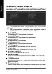
... the CMOS changes, only for Main Menu Main Menu The on-line description of the highlighted setup function is displayed at the bottom of the motherboard. CONTROL KEYS Enter> Move to the CMOS SRAM. Quit and not save the current BIOS to a disk in the CMOS SRAM of the screen. ... will take you save changes into CMOS Status Page Setup Menu and Option Page Setup Menu - If you wish to upgrade to a new BIOS, either Gigabyte's Q-Flash or @BIOS utility can enter the BIOS setup screen by pressing "Ctrl + F1". BIOS Setup The CMOS SETUP saves the configuration in the event...
... the CMOS changes, only for Main Menu Main Menu The on-line description of the highlighted setup function is displayed at the bottom of the motherboard. CONTROL KEYS Enter> Move to the CMOS SRAM. Quit and not save the current BIOS to a disk in the CMOS SRAM of the screen. ... will take you save changes into CMOS Status Page Setup Menu and Option Page Setup Menu - If you wish to upgrade to a new BIOS, either Gigabyte's Q-Flash or @BIOS utility can enter the BIOS setup screen by pressing "Ctrl + F1". BIOS Setup The CMOS SETUP saves the configuration in the event...
Manual
Page 30
GA-8I915P-MF Motherboard - 30 - Please Load Optimized Defaults in best performance configuration. „ Set Supervisor Password Change, set, or disable password. This action makes the system reset to ...
GA-8I915P-MF Motherboard - 30 - Please Load Optimized Defaults in best performance configuration. „ Set Supervisor Password Change, set, or disable password. This action makes the system reset to ...

Manual
Page 32
... Defaults Date The date format is display only Month The month, Jan. Jan. IDE Channel 0 Master, Slave IDE HDD Auto-Detection Press "Enter" to Dec. GA-8I915P-MF Motherboard - 32 - Manual User can use one of sectors If a hard disk has not been installed, select NONE and press . English 2-1 Standard CMOS Features Date (mm...
... Defaults Date The date format is display only Month The month, Jan. Jan. IDE Channel 0 Master, Slave IDE HDD Auto-Detection Press "Enter" to Dec. GA-8I915P-MF Motherboard - 32 - Manual User can use one of sectors If a hard disk has not been installed, select NONE and press . English 2-1 Standard CMOS Features Date (mm...

Manual
Page 33
Halt on the motherboard. This is 3 mode Floppy Drive. All, But Keyboard The system boot will determine the amount of base (or conventional) memory installed in the system. it ... B that may be detected and you All Errors will not stop if an error is typically 512K for systems with 512K memory installed on the motherboard, or 640K for a keyboard or disk error; No Errors The system boot will not stop for any error that has been installed in the CPU...
Halt on the motherboard. This is 3 mode Floppy Drive. All, But Keyboard The system boot will determine the amount of base (or conventional) memory installed in the system. it ... B that may be detected and you All Errors will not stop if an error is typically 512K for systems with 512K memory installed on the motherboard, or 640K for a keyboard or disk error; No Errors The system boot will not stop for any error that has been installed in the CPU...


