Manual
Page 4
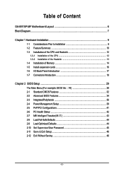
... GA-8I915P-MF Motherboard Layout 6 Block Diagram ...7 Chapter 1 Hardware Installation 9 1-1 Considerations Prior to Installation 9 1-2 Feature Summary 10 1-3 Installation of the CPU and Heatsink 12 1-3-1 Installation of the CPU 12 1-3-2 Installation of the Heatsink 13 1-4 Installation of Memory 14 1-5 Install expansion cards 16 1-6 I/O Back Panel Introduction 17 1-7 Connectors Introduction 18 Chapter 2 BIOS Setup 29 The Main Menu (For example: BIOS Ver. : F4 30 2-1 Standard CMOS Features 32 2-2 Advanced BIOS Features 34 2-3 IntegratedPeripherals 36 2-4 Power Management Setup...
... GA-8I915P-MF Motherboard Layout 6 Block Diagram ...7 Chapter 1 Hardware Installation 9 1-1 Considerations Prior to Installation 9 1-2 Feature Summary 10 1-3 Installation of the CPU and Heatsink 12 1-3-1 Installation of the CPU 12 1-3-2 Installation of the Heatsink 13 1-4 Installation of Memory 14 1-5 Install expansion cards 16 1-6 I/O Back Panel Introduction 17 1-7 Connectors Introduction 18 Chapter 2 BIOS Setup 29 The Main Menu (For example: BIOS Ver. : F4 30 2-1 Standard CMOS Features 32 2-2 Advanced BIOS Features 34 2-3 IntegratedPeripherals 36 2-4 Power Management Setup...
Manual
Page 10
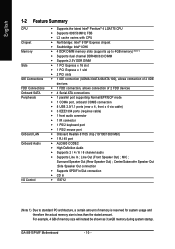
... audio connector Š 1 IR connector Š 1 PS/2 keyboard port Š 1 PS/2 mouse port Š Onboard Realtek 8110S chip (10/100/1000 Mbit) Š 1 RJ 45 port Š ALC880 CODEC Š High Definition Audio Š Supports 2 / 4 / 6 / 8 channel audio Š Supports Line In ; For example, 4 GB of memory is reserved for system usage and therefore the actual memory size is less than the stated amount. English 1-2 Feature Summary CPU Chipset Memory Slots IDE Connections FDD Connections Onboard SATA Peripherals Onboard LAN Onboard Audio I/O Control...
... audio connector Š 1 IR connector Š 1 PS/2 keyboard port Š 1 PS/2 mouse port Š Onboard Realtek 8110S chip (10/100/1000 Mbit) Š 1 RJ 45 port Š ALC880 CODEC Š High Definition Audio Š Supports 2 / 4 / 6 / 8 channel audio Š Supports Line In ; For example, 4 GB of memory is reserved for system usage and therefore the actual memory size is less than the stated amount. English 1-2 Feature Summary CPU Chipset Memory Slots IDE Connections FDD Connections Onboard SATA Peripherals Onboard LAN Onboard Audio I/O Control...

Manual
Page 12
... properly inserted, please replace the plastic covering and push the metal lever back into the socket in accordance with HT Technology - HT functionality requirement content : Enabling the functionality of the following conditions: 1. Chipset: An Intel® Chipset that the motherboard supports the CPU. 2. BIOS: A BIOS that the system bus frequency be set beyond the proper specifications, please do so according to the CPU during installation.) GA-8I915P-MF Motherboard - 12 - Fig...
... properly inserted, please replace the plastic covering and push the metal lever back into the socket in accordance with HT Technology - HT functionality requirement content : Enabling the functionality of the following conditions: 1. Chipset: An Intel® Chipset that the motherboard supports the CPU. 2. BIOS: A BIOS that the system bus frequency be set beyond the proper specifications, please do so according to the CPU during installation.) GA-8I915P-MF Motherboard - 12 - Fig...

Manual
Page 20
... GA-8I915P-MF Motherboard 2 1 - 20 - Please remember to connect the power to the CPU fan to the FDD drive. The types of the cable connects to prevent CPU overheating and failure. 1 CPU_FAN 1 SYS_FAN Pin No. 1 2 3 4 Definition GND +12V Sense Speed Control (Only for CPU_FAN) power connector and possesses a foolproof connection design. Caution! A red power connector wire indicates a positive connection and requires a +12V power voltage. Most coolers are : 360KB, 720KB, 1.2MB, 1.44MB and 2.88MB. The black connector wire is used...
... GA-8I915P-MF Motherboard 2 1 - 20 - Please remember to connect the power to the CPU fan to the FDD drive. The types of the cable connects to prevent CPU overheating and failure. 1 CPU_FAN 1 SYS_FAN Pin No. 1 2 3 4 Definition GND +12V Sense Speed Control (Only for CPU_FAN) power connector and possesses a foolproof connection design. Caution! A red power connector wire indicates a positive connection and requires a +12V power voltage. Most coolers are : 360KB, 720KB, 1.2MB, 1.44MB and 2.88MB. The black connector wire is used...

Manual
Page 21
... the IDE device). 40 39 2 1 7) S_ATA0/S_ATA1/S_ATA2/S_ATA3 (Serial ATA Connector, Controlled by ICH6) Serial ATA can provide 150MB/s transfer rate. Pin No. If you wish to connect two IDE devices, please set the jumper on one IDE cable, and the single IDE cable can connect to one IDE device as Master and the other as Slave (for the Serial ATA and install the proper driver in order to the instructions located on settings...
... the IDE device). 40 39 2 1 7) S_ATA0/S_ATA1/S_ATA2/S_ATA3 (Serial ATA Connector, Controlled by ICH6) Serial ATA can provide 150MB/s transfer rate. Pin No. If you wish to connect two IDE devices, please set the jumper on one IDE cable, and the single IDE cable can connect to one IDE device as Master and the other as Slave (for the Serial ATA and install the proper driver in order to the instructions located on settings...

Manual
Page 22
... your chassis front panel to the F_PANEL connector according to the pin assignment below. HDHD+ HD (IDE Hard Disk Active LED) SPEAK (Speaker Connector) RES (Reset Switch) PW (Power Switch) MSG(Message LED/Power/Sleep LED) NC IDE Hard Disk Active LED Reset Switch Pin 1: LED anode(+) Pin 2: LED cathode(-) Pin 1: VCC(+) Pin 2- Pin 3: NC Pin 4: Data(-) Open: Normal Operation Close: Reset Hardware System Open: Normal Operation Close: Power On/Off Pin 1: LED anode(+) Pin 2: LED cathode(-) NC GA-8I915P-MF Motherboard - 22 - Message LED/ Power/ Sleep LED Power Switch Speaker Connector SPEAK...
... your chassis front panel to the F_PANEL connector according to the pin assignment below. HDHD+ HD (IDE Hard Disk Active LED) SPEAK (Speaker Connector) RES (Reset Switch) PW (Power Switch) MSG(Message LED/Power/Sleep LED) NC IDE Hard Disk Active LED Reset Switch Pin 1: LED anode(+) Pin 2: LED cathode(-) Pin 1: VCC(+) Pin 2- Pin 3: NC Pin 4: Data(-) Open: Normal Operation Close: Reset Hardware System Open: Normal Operation Close: Power On/Off Pin 1: LED anode(+) Pin 2: LED cathode(-) NC GA-8I915P-MF Motherboard - 22 - Message LED/ Power/ Sleep LED Power Switch Speaker Connector SPEAK...
Manual
Page 30
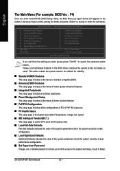
... the System auto detect Temperature, voltage, fan, speed. „ MB Intelligent Tweaker(M.I .T.) ESC: Quit F8: Q-Flash Load Fail-Safe Defaults Load Optimized Defaults Set Supervisor Password Set User Password Save & Exit Setup Exit Without Saving KLJI: Select Item F10: Save & Exit Setup Time, Date, Hard Disk Type... GA-8I915P-MF Motherboard - 30 - It allows you want, please press "Ctrl+F1" to accept or enter the sub-menu. English The Main Menu (For example: BIOS Ver. : F4) Once you enter Award BIOS CMOS Setup Utility, the Main Menu (as...
... the System auto detect Temperature, voltage, fan, speed. „ MB Intelligent Tweaker(M.I .T.) ESC: Quit F8: Q-Flash Load Fail-Safe Defaults Load Optimized Defaults Set Supervisor Password Set User Password Save & Exit Setup Exit Without Saving KLJI: Select Item F10: Save & Exit Setup Time, Date, Hard Disk Type... GA-8I915P-MF Motherboard - 30 - It allows you want, please press "Ctrl+F1" to accept or enter the sub-menu. English The Main Menu (For example: BIOS Ver. : F4) Once you enter Award BIOS CMOS Setup Utility, the Main Menu (as...

Manual
Page 32
... IDE devices during POST(default) None Select this information. GA-8I915P-MF Motherboard - 32 - English 2-1 Standard CMOS Features Date (mm:dd:yy) Time (hh:mm:ss) CMOS Setup Utility-Copyright (C) 1984-2004 Award Software Standard CMOS Features Thu, Apr 29 2004 22:31:24 Item Help Menu Level` ` IDE Channel 0 Master ` IDE Channel 0 Slave [None] [None] Change the day, month, year Drive A Drive B Floppy 3 Mode Suport Holt On [1.44M, 3.5"] [None] [Disabled] [All, But Keyboard] Sun. Enter the appropriate option...
... IDE devices during POST(default) None Select this information. GA-8I915P-MF Motherboard - 32 - English 2-1 Standard CMOS Features Date (mm:dd:yy) Time (hh:mm:ss) CMOS Setup Utility-Copyright (C) 1984-2004 Award Software Standard CMOS Features Thu, Apr 29 2004 22:31:24 Item Help Menu Level` ` IDE Channel 0 Master ` IDE Channel 0 Slave [None] [None] Change the day, month, year Drive A Drive B Floppy 3 Mode Suport Holt On [1.44M, 3.5"] [None] [Disabled] [All, But Keyboard] Sun. Enter the appropriate option...

Manual
Page 34
... you install a processor which supports this menu. CDROM Select your boot device priority by Hard Disk. to exit this function. USB-FDD Select your boot device priority by USB-HDD. Hard Disk Boot Priority Select boot sequence for onboard(or add-on cards) SCSI, RAID, etc. LAN Select your boot device priority by CDROM. USB-HDD Select your boot device priority by ZIP. Disabled Select your boot device priority by LAN. GA-8I915P-MF Motherboard - 34 - Password Check Setup System The system will boot but will not access to Setup...
... you install a processor which supports this menu. CDROM Select your boot device priority by Hard Disk. to exit this function. USB-FDD Select your boot device priority by USB-HDD. Hard Disk Boot Priority Select boot sequence for onboard(or add-on cards) SCSI, RAID, etc. LAN Select your boot device priority by CDROM. USB-HDD Select your boot device priority by ZIP. Disabled Select your boot device priority by LAN. GA-8I915P-MF Motherboard - 34 - Password Check Setup System The system will boot but will not access to Setup...

Manual
Page 43
...control specifications. CPU Clock Ratio This setup option will display "Locked" and read only if the CPU ratio is enabled. Auto Set Memory frequency by CPU detection. Auto BIOS autodetects the type of CPU fan you installed and sets the optimal CPU Smart FAN control mode for FSB(Front Side Bus) frequency=800MHz, 2.0 Memory Frequency = Host clock X 2.0. 2.66 Memory Frequency = Host clock X 2.66. for it. (Default value) Voltage Set to PWM when you use a CPU fan with 3-pin or 4-pin power cables. For power end-user use a CPU fan with a 4-pin fan power cable. PWM Set to Voltage...
...control specifications. CPU Clock Ratio This setup option will display "Locked" and read only if the CPU ratio is enabled. Auto Set Memory frequency by CPU detection. Auto BIOS autodetects the type of CPU fan you installed and sets the optimal CPU Smart FAN control mode for FSB(Front Side Bus) frequency=800MHz, 2.0 Memory Frequency = Host clock X 2.0. 2.66 Memory Frequency = Host clock X 2.66. for it. (Default value) Voltage Set to PWM when you use a CPU fan with 3-pin or 4-pin power cables. For power end-user use a CPU fan with a 4-pin fan power cable. PWM Set to Voltage...

Manual
Page 45
.../User Password CMOS Setup Utility-Copyright (C) 1984-2004 Award Software ` Standard CMOS Features ` Advanced BIOS Features ` Integrated Peripherals ` Power Management Setup ` PnP/PCI ConfigurationEsnter Password: ` PC Health Status ` MB Intelligent Tweaker(M.I.T.) Load Fail-Safe Defaults Load Optimized Defaults Set Supervisor Password Set User Password Save & Exit Setup Exit Without Saving ESC: Quit F8: Q-Flash KLJI: Select Item F10: Save & Exit Setup Change/Set/Disable Password Selecting this function, the following message will appear to confirm the password being disabled. Type...
.../User Password CMOS Setup Utility-Copyright (C) 1984-2004 Award Software ` Standard CMOS Features ` Advanced BIOS Features ` Integrated Peripherals ` Power Management Setup ` PnP/PCI ConfigurationEsnter Password: ` PC Health Status ` MB Intelligent Tweaker(M.I.T.) Load Fail-Safe Defaults Load Optimized Defaults Set Supervisor Password Set User Password Save & Exit Setup Exit Without Saving ESC: Quit F8: Q-Flash KLJI: Select Item F10: Save & Exit Setup Change/Set/Disable Password Selecting this function, the following message will appear to confirm the password being disabled. Type...

Manual
Page 47
... the driver CD, "Xpress Install" will auto start and show a question mark "?" Some device drivers will continue to install other drivers. After restarting your system the "Xpress Install" will restart your CD-ROM drive, the driver CD-title will scan automatically the system and then list all items defaulted. After install Windows Service Pack, it will show the installation guide. Insert the driver CD-title that came with your motherboard into...
... the driver CD, "Xpress Install" will auto start and show a question mark "?" Some device drivers will continue to install other drivers. After restarting your system the "Xpress Install" will restart your CD-ROM drive, the driver CD-title will scan automatically the system and then list all items defaulted. After install Windows Service Pack, it will show the installation guide. Insert the driver CD-title that came with your motherboard into...

Manual
Page 51
... PC chassis and short-circuit the "Clear CMOS" pins or the battery on the U-Plus D.P.S. With added branded memory module information, users are mounted on the motherboard to reset the system back to quickly download and update their computer system to provide a more user-friendly and reliable platform for intelligent indication of all platform performance settings into different modes within BIOS setup in order to change BIOS feature settings with...
... PC chassis and short-circuit the "Clear CMOS" pins or the battery on the U-Plus D.P.S. With added branded memory module information, users are mounted on the motherboard to reset the system back to quickly download and update their computer system to provide a more user-friendly and reliable platform for intelligent indication of all platform performance settings into different modes within BIOS setup in order to change BIOS feature settings with...
Manual
Page 52
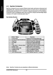
...Enters the Smart-Fan setting page 4. GA-8I915P-MF Motherboard - 52 - for special enhancement for CPU and Memory, 3) Smart-Fan control for managing fan speed control of CPU frequency 8. C.I.A./C.I.A.2 and M.I.B./M.I.B.2 Enters the C.I.A./2 and M.I .A. GO Confirmation and Execution button 6. Overclocking Enters the Overclocking setting page 2. Function display LEDs Shows the current functions status 9. Help button Display EasyTuneTM 5 Help file 11. Featuring several powerful yet easy to GIGABYTE website 10. PC Health Enters the PC Health setting page 5. "Easy Mode...
...Enters the Smart-Fan setting page 4. GA-8I915P-MF Motherboard - 52 - for special enhancement for CPU and Memory, 3) Smart-Fan control for managing fan speed control of CPU frequency 8. C.I.A./C.I.A.2 and M.I.B./M.I.B.2 Enters the C.I.A./2 and M.I .A. GO Confirmation and Execution button 6. Overclocking Enters the Overclocking setting page 2. Function display LEDs Shows the current functions status 9. Help button Display EasyTuneTM 5 Help file 11. Featuring several powerful yet easy to GIGABYTE website 10. PC Health Enters the PC Health setting page 5. "Easy Mode...

Manual
Page 54
... key. 2. GA-8I915P-MF Motherboard - 54 - System storage capacity as well as drive reading/writing speed will affect backup speed. 3. Press DEL to enter SETUP / Q-Flash, F9 For Xpress Recovery 08/16/2002-I845GE-6A69YG01C-00 F9 For Xpress Recovery Xpress Recovery V1.0 (C) Copy Right 2003. GIGABYTE Technology CO. , Ltd. 1. Execute Backup Utility 2. It is recommended that Xpress Recovery be immediately installed after OS and all required driver and software installations are complete. Remove...
... key. 2. GA-8I915P-MF Motherboard - 54 - System storage capacity as well as drive reading/writing speed will affect backup speed. 3. Press DEL to enter SETUP / Q-Flash, F9 For Xpress Recovery 08/16/2002-I845GE-6A69YG01C-00 F9 For Xpress Recovery Xpress Recovery V1.0 (C) Copy Right 2003. GIGABYTE Technology CO. , Ltd. 1. Execute Backup Utility 2. It is recommended that Xpress Recovery be immediately installed after OS and all required driver and software installations are complete. Remove...
Manual
Page 56
... updating BIOS to enter SETUP / Dual BIOS / Q-Flash / F9 For Xpress Recovery 08/07/2003-i875P-6A79BG03C-00 GA-8I915P-MF Motherboard - 56 - In the following sections, we take GA-8KNXP Ultra as the example to use Q-Flash utility. Using Q-FlashTM indicating no more fooling around with any complicated instructions and operating system since it with model name.Fxx. We are combined in Flash ROM. The BIOS upgrading guides below first. 1. In the BIOS menu of Gigabyte motherboards...
... updating BIOS to enter SETUP / Dual BIOS / Q-Flash / F9 For Xpress Recovery 08/07/2003-i875P-6A79BG03C-00 GA-8I915P-MF Motherboard - 56 - In the following sections, we take GA-8KNXP Ultra as the example to use Q-Flash utility. Using Q-FlashTM indicating no more fooling around with any complicated instructions and operating system since it with model name.Fxx. We are combined in Flash ROM. The BIOS upgrading guides below first. 1. In the BIOS menu of Gigabyte motherboards...

Manual
Page 57
... Enter key on your keyboard to enable execution of four actions needed to enter BIOS menu. CMOS Setup Utility-Copyright (C) 1984-2004 Award Software Standard CMOS Features Advanced BIOS Features Integrated Peripherals Power Management Setup PnP/PCI Configurations PC Health Status MB Intelligent Tweaker(M.I.T.) ESC: Quit F8: Dual BIOS/Q-Flash Select Language Load Fail-Safe Defaults Load Optimized Defaults Set Supervisor Password Set User Password Save & Exit Setup Exit Without Saving F3: Change Language F10: Save & Exit Setup Time, Date, Hard Disk Type... Pressing the buttons...
... Enter key on your keyboard to enable execution of four actions needed to enter BIOS menu. CMOS Setup Utility-Copyright (C) 1984-2004 Award Software Standard CMOS Features Advanced BIOS Features Integrated Peripherals Power Management Setup PnP/PCI Configurations PC Health Status MB Intelligent Tweaker(M.I.T.) ESC: Quit F8: Dual BIOS/Q-Flash Select Language Load Fail-Safe Defaults Load Optimized Defaults Set Supervisor Password Set User Password Save & Exit Setup Exit Without Saving F3: Change Language F10: Save & Exit Setup Time, Date, Hard Disk Type... Pressing the buttons...

Manual
Page 59
... Range Protection Disable Boot From Main Bios !A! Pass !! Load Default Settings Save Settings to CMOS Q-Flash Utility Load Main BIOS from Floppy Load Backup BIOS from Floppy Save Main BIOS to Floppy Save Backup BIOS to Floppy Enter : Run :Move ESC:Reset F10:Power Off You can repeat Step 1 to 4 to Floppy Enter : Run :Move ESC:Reset F10:Power Off After system reboots, you may find the BIOS version on your boot screen becomes the one you exit Q-Flash. Appendix Press Y button on your keyboard after updating. Please...
... Range Protection Disable Boot From Main Bios !A! Pass !! Load Default Settings Save Settings to CMOS Q-Flash Utility Load Main BIOS from Floppy Load Backup BIOS from Floppy Save Main BIOS to Floppy Save Backup BIOS to Floppy Enter : Run :Move ESC:Reset F10:Power Off You can repeat Step 1 to 4 to Floppy Enter : Run :Move ESC:Reset F10:Power Off After system reboots, you may find the BIOS version on your boot screen becomes the one you exit Q-Flash. Appendix Press Y button on your keyboard after updating. Please...

Manual
Page 60
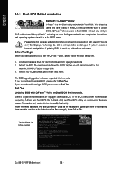
... PnP/PCI Configurations Set User Password PC Health Status Save & Exit Setup MB Intelligent Tweaker(M.I .T.) Exit Without Saving ESC: Quit F8: Dual BIOS/Q-Flash F3: Change Language F10: Save & Exit Setup Time, Date, Hard Disk Type... This part guides users of single-BIOS motherboards how to enter BIOS menu after you are in BIOS menu, move to Load Fail-Safe Defaults item and press Enter to load defaults. 7. The procedure is completed. Part Two: Updating BIOS with Q-FlashTM Utility on your keyboard to load BIOS Fail-Safe Defaults. GA-8I915P-MF Motherboard - 60...
... PnP/PCI Configurations Set User Password PC Health Status Save & Exit Setup MB Intelligent Tweaker(M.I .T.) Exit Without Saving ESC: Quit F8: Dual BIOS/Q-Flash F3: Change Language F10: Save & Exit Setup Time, Date, Hard Disk Type... This part guides users of single-BIOS motherboards how to enter BIOS menu after you are in BIOS menu, move to Load Fail-Safe Defaults item and press Enter to load defaults. 7. The procedure is completed. Part Two: Updating BIOS with Q-FlashTM Utility on your keyboard to load BIOS Fail-Safe Defaults. GA-8I915P-MF Motherboard - 60...

Manual
Page 69
... I disable onboard VGA card in , so you can use the IDE 2? If not, please change any cable that is not provided with the motherboard package to see some boards, a small amount of electricity is kept on standby after turning up the speaker to enter BIOS and load Fail-Safe Defaults. 7. If the cable is your board doesn't have connected any setting manually to load Fail-Safe Defaults (Or Load BIOS Defaults) after updating BIOS. Appendix If your own cable, please remove it...
... I disable onboard VGA card in , so you can use the IDE 2? If not, please change any cable that is not provided with the motherboard package to see some boards, a small amount of electricity is kept on standby after turning up the speaker to enter BIOS and load Fail-Safe Defaults. 7. If the cable is your board doesn't have connected any setting manually to load Fail-Safe Defaults (Or Load BIOS Defaults) after updating BIOS. Appendix If your own cable, please remove it...


