Manual
Page 2
... 2 - If you do not want to IDE2/IDE3 ports ). Then connect the power connector from your hard drives to create RAID.array on the motherboard. (To ensure that your IDE CD-ROM can work properly, please connect it is recommended that you may prepare only one hard drive. (b) An ...empty formatted floppy disk. (c) Windows XP/2000 setup disk. (d) Driver CD for your motherboard. (1) Installing IDE hard drive(s) in BIOS Setup. (3)* Configure RAID set up IDE RAID hard drive(s), you do not plan to create RAID with the ...
... 2 - If you do not want to IDE2/IDE3 ports ). Then connect the power connector from your hard drives to create RAID.array on the motherboard. (To ensure that your IDE CD-ROM can work properly, please connect it is recommended that you may prepare only one hard drive. (b) An ...empty formatted floppy disk. (c) Windows XP/2000 setup disk. (d) Driver CD for your motherboard. (1) Installing IDE hard drive(s) in BIOS Setup. (3)* Configure RAID set up IDE RAID hard drive(s), you do not plan to create RAID with the ...
Manual
Page 10
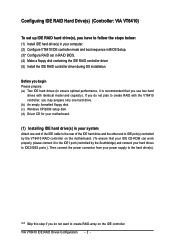
... IDE RAID Drives Configuration - 10 - Quit the installation utility first. Go to the BootDrv folder and look for the IDE RAID controller from the motherboard driver CD to ¤å a floppy disk. Without the ¤¤ driver, the hard disk may not be recognized during OS installation.... and right-click the CD-ROM icon (this procedure assumes Drive D) and select Open (Figure 14). Step 1: Find an available system and insert the motherboard driver CD into the CD-ROM drive. Ác (4) Making a IDE RAID controller driver disk Åé To install Windows 2000/XP onto a...
... IDE RAID Drives Configuration - 10 - Quit the installation utility first. Go to the BootDrv folder and look for the IDE RAID controller from the motherboard driver CD to ¤å a floppy disk. Without the ¤¤ driver, the hard disk may not be recognized during OS installation.... and right-click the CD-ROM icon (this procedure assumes Drive D) and select Open (Figure 14). Step 1: Find an available system and insert the motherboard driver CD into the CD-ROM drive. Ác (4) Making a IDE RAID controller driver disk Åé To install Windows 2000/XP onto a...
Manual
Page 11
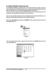
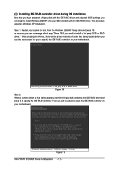
Then it will take about one minute to copy the IDE RAID driver from the motherboard driver CD to Figure 16 will appear. Figure 17 - 11 - An MS-DOS prompt screen similar to the floppy disk. VIA VT6410 IDE RAID Drives Configuration You have copied the IDE RAID driver successfully. Step 5: Press 0 to select VIA 6410 RAID. Step 3: Double-click MENU.exe. Figure 16 Step 4: Insert an empty floppy disk and press H to exit when the procedure is completed (Figure 17).
Then it will take about one minute to copy the IDE RAID driver from the motherboard driver CD to Figure 16 will appear. Figure 17 - 11 - An MS-DOS prompt screen similar to the floppy disk. VIA VT6410 IDE RAID Drives Configuration You have copied the IDE RAID driver successfully. Step 5: Press 0 to select VIA 6410 RAID. Step 3: Double-click MENU.exe. Figure 16 Step 4: Insert an empty floppy disk and press H to exit when the procedure is completed (Figure 17).
Manual
Page 12
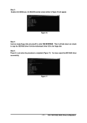
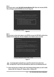
...with the IDE RAID driver and adjusted BIOS settings, you will be a few moments of one or more mass storage devices installed in your motherboard. Then you can begin to install Windows 2000/XP onto your IDE hard disk with Windows, press ENTER. After pressing the F6 key,... disk controllers for use with the IDE RAID driver. This procedure ¤¤ assumes Windows XP installation. ¤å Step 1: Restart your motherboard. Windows Setup Press F6 if you have any device support disks from a mass storage device manufacturer, or do not have chosen to manually specify an...
...with the IDE RAID driver and adjusted BIOS settings, you will be a few moments of one or more mass storage devices installed in your motherboard. Then you can begin to install Windows 2000/XP onto your IDE hard disk with Windows, press ENTER. After pressing the F6 key,... disk controllers for use with the IDE RAID driver. This procedure ¤¤ assumes Windows XP installation. ¤å Step 1: Restart your motherboard. Windows Setup Press F6 if you have any device support disks from a mass storage device manufacturer, or do not have chosen to manually specify an...
Manual
Page 13
... or copy the correct IDE RAID driver again from the floppy disk. The driver installation will begin to load the IDE RAID driver from the motherboard driver CD.
... or copy the correct IDE RAID driver again from the floppy disk. The driver installation will begin to load the IDE RAID driver from the motherboard driver CD.

Manual
Page 1
GA-8I915P-D Intel® Pentium® 4 LGA775 Processor Motherboard User's Manual Rev. 1002 12ME-8I915PD-1002R * The WEEE marking on the product indicates this product must not be disposed of with user's other household waste and must be handed over to a designated collection point for the recycling of waste electrical and electronic equipment!! * The WEEE marking applies only in European Union's member states.
GA-8I915P-D Intel® Pentium® 4 LGA775 Processor Motherboard User's Manual Rev. 1002 12ME-8I915PD-1002R * The WEEE marking on the product indicates this product must not be disposed of with user's other household waste and must be handed over to a designated collection point for the recycling of waste electrical and electronic equipment!! * The WEEE marking applies only in European Union's member states.

Manual
Page 2
Motherboard GA-8I915P-D Sep. 9, 2005 Motherboard GA-8I915P-D Sep. 9, 2005
Motherboard GA-8I915P-D Sep. 9, 2005 Motherboard GA-8I915P-D Sep. 9, 2005
Manual
Page 4
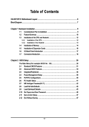
Table of Contents GA-8I915P-D Motherboard Layout 6 Block Diagram ...7 Chapter 1 Hardware Installation 9 1-1 Considerations Prior to Installation 9 1-2 Feature Summary 10 1-3 Installation of the CPU and Heatsink 12 1-3-1 Installation of the CPU 12 1-3-2 ...
Table of Contents GA-8I915P-D Motherboard Layout 6 Block Diagram ...7 Chapter 1 Hardware Installation 9 1-1 Considerations Prior to Installation 9 1-2 Feature Summary 10 1-3 Installation of the CPU and Heatsink 12 1-3-1 Installation of the CPU 12 1-3-2 ...
Manual
Page 6
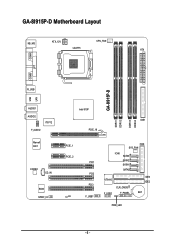
GA-8I915P-D Motherboard Layout KB_MS ATX_12V CPU_FAN LGA775 ATX COMA LPT COMB R_USB GA-8I915P-D LAN USB AUDIO1 AUDIO2 IT8712 F_AUDIO Marvell 8001 CODEC CD_IN BIOS SPDIF_IO Intel 915P IDE1 PCIE_16 DDRII1 DDRII2 DDRII3 DDRII4 PCIE_1 PCIE_2 CI PCI1 PCI2 PCI3 F_USB1 FDD SYS_FAN ICH6 SATA3 SATA2 SATA1 SATA0 VT6410 F_USB2 CLR_CMOS F_PANEL IDE3 IDE2 BAT PWR_LED - 6 -
GA-8I915P-D Motherboard Layout KB_MS ATX_12V CPU_FAN LGA775 ATX COMA LPT COMB R_USB GA-8I915P-D LAN USB AUDIO1 AUDIO2 IT8712 F_AUDIO Marvell 8001 CODEC CD_IN BIOS SPDIF_IO Intel 915P IDE1 PCIE_16 DDRII1 DDRII2 DDRII3 DDRII4 PCIE_1 PCIE_2 CI PCI1 PCI2 PCI3 F_USB1 FDD SYS_FAN ICH6 SATA3 SATA2 SATA1 SATA0 VT6410 F_USB2 CLR_CMOS F_PANEL IDE3 IDE2 BAT PWR_LED - 6 -
Manual
Page 7
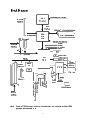
... Center/Subwoofer Speaker Out Side Speaker Out MIC Line-Out Line-In SPDIF In SPDIF Out (Note) To use a DDRII 600 memory module on the motherboard, you must install an 800MHz FSB processor and overclock in BIOS. - 7 -
... Center/Subwoofer Speaker Out Side Speaker Out MIC Line-Out Line-In SPDIF In SPDIF Out (Note) To use a DDRII 600 memory module on the motherboard, you must install an 800MHz FSB processor and overclock in BIOS. - 7 -

Manual
Page 9
...). Please make sure there are required for warranty validation. 2. Damage due to natural disaster, accident or human cause. 2. When handling the motherboard, avoid touching any metal leads or connectors. 3. Please verify that all cables and power connectors are uncertain about any installation steps or have ...1. Damage as physical harm to use exceeding the permitted parameters. 6. Turning on an uneven surface. 7. Thus, prior to be an unofficial Gigabyte product. - 9 - Product determined to installation, please follow the instructions below: 1. Damage due to the user. 8.
...). Please make sure there are required for warranty validation. 2. Damage due to natural disaster, accident or human cause. 2. When handling the motherboard, avoid touching any metal leads or connectors. 3. Please verify that all cables and power connectors are uncertain about any installation steps or have ...1. Damage as physical harm to use exceeding the permitted parameters. 6. Turning on an uneven surface. 7. Thus, prior to be an unofficial Gigabyte product. - 9 - Product determined to installation, please follow the instructions below: 1. Damage due to the user. 8.
Manual
Page 10
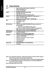
...4 DDR II DIMM memory slots (supports up to standard PC architecture, a certain amount of memory is less than the stated amount. GA-8I915P-D Motherboard - 10 - English 1-2 Feature Summary CPU Chipset Memory Slots IDE Connections FDD Connections Onboard SATA Peripherals Onboard LAN Š Supports the ...IDE3)(Note 3) Š 1 FDD connection, allows connection of 2 FDD devices Š 4 Serial ATA connections Š Supported on the motherboard, you must install an 800MHz FSB processor and overclock in BIOS. (Note 3) Only support ATAPI mode for system usage and therefore the actual ...
...4 DDR II DIMM memory slots (supports up to standard PC architecture, a certain amount of memory is less than the stated amount. GA-8I915P-D Motherboard - 10 - English 1-2 Feature Summary CPU Chipset Memory Slots IDE Connections FDD Connections Onboard SATA Peripherals Onboard LAN Š Supports the ...IDE3)(Note 3) Š 1 FDD connection, allows connection of 2 FDD devices Š 4 Serial ATA connections Š Supported on the motherboard, you must install an 800MHz FSB processor and overclock in BIOS. (Note 3) Only support ATAPI mode for system usage and therefore the actual ...

Manual
Page 11
...; Over Clock via BIOS (CPU/DDR/PCIE) Form Factor Š ATX form factor; 30.5cm x 22.0cm (Note 4) EasyTune functions may vary depending on different motherboards. - 11 - Surround Speaker Out (Rear Speaker Out) ; Center/Subwoofer Speaker Out ; English Onboard Audio Š ALC850 CODEC (UAJ) Š Supports 2 / 4 / 6 / 8 channel audio Š Supports Line...
...; Over Clock via BIOS (CPU/DDR/PCIE) Form Factor Š ATX form factor; 30.5cm x 22.0cm (Note 4) EasyTune functions may vary depending on different motherboards. - 11 - Surround Speaker Out (Rear Speaker Out) ; Center/Subwoofer Speaker Out ; English Onboard Audio Š ALC850 CODEC (UAJ) Š Supports 2 / 4 / 6 / 8 channel audio Š Supports Line...
Manual
Page 12
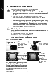
... - Please make sure that might cause damage to the upright position. It is installed on the CPU socket to the CPU during installation.) GA-8I915P-D Motherboard - 12 - If you install the CPU in the wrong direction, the CPU will not insert properly. Please take note of the one ...edge of the CPU socket. Fig. 3 Notice the small gold colored triangle located on the CPU socket. Avoid twisting or bending motions that the motherboard supports the CPU. 2. If this occurs, please change the insert direction of the CPU. BIOS: A BIOS that has optimizations for your hardware...
... - Please make sure that might cause damage to the upright position. It is installed on the CPU socket to the CPU during installation.) GA-8I915P-D Motherboard - 12 - If you install the CPU in the wrong direction, the CPU will not insert properly. Please take note of the one ...edge of the CPU socket. Fig. 3 Notice the small gold colored triangle located on the CPU socket. Avoid twisting or bending motions that the motherboard supports the CPU. 2. If this occurs, please change the insert direction of the CPU. BIOS: A BIOS that has optimizations for your hardware...

Manual
Page 13
... Pin Fig.1 Please apply an even layer of heatsink paste on the surface of motherboard after installing. Fig. 4 Please make sure the push pins aim to the CPU fan header located on the motherboard.Pressing down the push pins diagonally. Fig. 6 Finally, please attach the power ... doesn't face inwards before installation. (This instruction is to install.) Please note the direction of the heatsink to the pin hole on the motherboard. Hardware Installation Fig. 2 (Turning the push pin along the direction of arrow is to the heatsink installation section of the user manual) Fig...
... Pin Fig.1 Please apply an even layer of heatsink paste on the surface of motherboard after installing. Fig. 4 Please make sure the push pins aim to the CPU fan header located on the motherboard.Pressing down the push pins diagonally. Fig. 6 Finally, please attach the power ... doesn't face inwards before installation. (This instruction is to install.) Please note the direction of the heatsink to the pin hole on the motherboard. Hardware Installation Fig. 2 (Turning the push pin along the direction of arrow is to the heatsink installation section of the user manual) Fig...

Manual
Page 14
..., so the DIMM memory module can be used is switched off to lock the DIMM module. Memory modules are unable to remove the DIMM module. GA-8I915P-D Motherboard - 14 - Please make sure that the memory used . 2. Before installing or removing memory modules, please make sure that the computer power is supported by the...
..., so the DIMM memory module can be used is switched off to lock the DIMM module. Memory modules are unable to remove the DIMM module. GA-8I915P-D Motherboard - 14 - Please make sure that the memory used . 2. Before installing or removing memory modules, please make sure that the computer power is supported by the...
Manual
Page 16
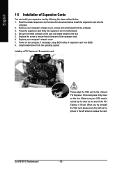
...Power on the slot. Remove your computer's chassis cover. 7. Be sure the metal contacts on the card are indeed seated in motherboard. 4. Install related driver from the computer. 3. When you try uninstall the VGA card, please press the latch as the picture ... outlined below: 1. Read the related expansion card's instruction document before install the expansion card into expansion slot in the slot. 5. GA-8I915P-D Motherboard - 16 - Replace your computer's chassis cover, screws and slot bracket from the operating system. English 1-5 Installation of Expansion Cards ...
...Power on the slot. Remove your computer's chassis cover. 7. Be sure the metal contacts on the card are indeed seated in motherboard. 4. Install related driver from the computer. 3. When you try uninstall the VGA card, please press the latch as the picture ... outlined below: 1. Read the related expansion card's instruction document before install the expansion card into expansion slot in the slot. 5. GA-8I915P-D Motherboard - 16 - Replace your computer's chassis cover, screws and slot bracket from the operating system. English 1-5 Installation of Expansion Cards ...

Manual
Page 18
English 1-7 Connectors Introduction 1 3 2 6 10 4 5 7 11 6 15 12 16 14 13 9 8 1) ATX_12V 2) ATX (Power Connector) 3) CPU_FAN 4) SYS_FAN 5) FDD 6) IDE1/IDE2/IDE3 7) SATA0 / SATA1 / SATA2 / SATA3 8) F_PANEL 9) PWR_LED 10) F_AUDIO 11) CD_IN 12) SPDIF_IO 13) F_USB1 / F_USB2 14) CI 15) CLR_CMOS 16) BAT GA-8I915P-D Motherboard - 18 -
English 1-7 Connectors Introduction 1 3 2 6 10 4 5 7 11 6 15 12 16 14 13 9 8 1) ATX_12V 2) ATX (Power Connector) 3) CPU_FAN 4) SYS_FAN 5) FDD 6) IDE1/IDE2/IDE3 7) SATA0 / SATA1 / SATA2 / SATA3 8) F_PANEL 9) PWR_LED 10) F_AUDIO 11) CD_IN 12) SPDIF_IO 13) F_USB1 / F_USB2 14) CI 15) CLR_CMOS 16) BAT GA-8I915P-D Motherboard - 18 -

Manual
Page 19
...connector, the power supply can lead to an unstable system or a system that all the components on the motherboard. Align the power connector with its proper location on the motherboard before plugging in the power cord ; The ATX_12V power connector mainly supplies power to start . It is... system voltage requirements. Caution! Pin No. If you use a 24-pin ATX power supply, please remove the small cover on the power connector on the motherboard and connect tightly. If the ATX_12V power connector is unable to the CPU. Definition 12 24 1 3.3V 2 3.3V 3 GND 4 +5V 5 GND 6...
...connector, the power supply can lead to an unstable system or a system that all the components on the motherboard. Align the power connector with its proper location on the motherboard before plugging in the power cord ; The ATX_12V power connector mainly supplies power to start . It is... system voltage requirements. Caution! Pin No. If you use a 24-pin ATX power supply, please remove the small cover on the power connector on the motherboard and connect tightly. If the ATX_12V power connector is unable to the CPU. Definition 12 24 1 3.3V 2 3.3V 3 GND 4 +5V 5 GND 6...

Manual
Page 20
... red power connector wire to prevent system overheating and failure. Please remember to connect the power to the cooler to the pin1 position. 34 33 GA-8I915P-D Motherboard 2 1 - 20 - Most coolers are : 360KB, 720KB, 1.2MB, 1.44MB and 2.88MB. A red power connector wire indicates a positive connection and requires a +12V power voltage. The types of...
... red power connector wire to prevent system overheating and failure. Please remember to connect the power to the cooler to the pin1 position. 34 33 GA-8I915P-D Motherboard 2 1 - 20 - Most coolers are : 360KB, 720KB, 1.2MB, 1.44MB and 2.88MB. A red power connector wire indicates a positive connection and requires a +12V power voltage. The types of...


