
Manual
Page 4
Table of Content GA-8I915ME Series Motherboard Layout 6 Block Diagram ...7 Chapter 1 Hardware Installation 9 1-1 Considerations Prior to Installation 9 1-2 Feature Summary 10 1-3 Installation of the CPU and ...G.E.A.R 17 1-5-2 Graphics Card Support List 17 1-6 I/O Back Panel Introduction 20 1-7 Connectors Introduction 21 Chapter 2 BIOS Setup 33 The Main Menu ...34 (For example: GA-8I915ME-GV / BIOS Ver.: F2 34 2-1 Standard CMOS Features 36 2-2 Advanced BIOS Features 38 2-3 IntegratedPeripherals 40 2-4 Power Management Setup 42 2-5 PnP/PCI Configurations 44 2-6 PC Health Status 44...
Table of Content GA-8I915ME Series Motherboard Layout 6 Block Diagram ...7 Chapter 1 Hardware Installation 9 1-1 Considerations Prior to Installation 9 1-2 Feature Summary 10 1-3 Installation of the CPU and ...G.E.A.R 17 1-5-2 Graphics Card Support List 17 1-6 I/O Back Panel Introduction 20 1-7 Connectors Introduction 21 Chapter 2 BIOS Setup 33 The Main Menu ...34 (For example: GA-8I915ME-GV / BIOS Ver.: F2 34 2-1 Standard CMOS Features 36 2-2 Advanced BIOS Features 38 2-3 IntegratedPeripherals 40 2-4 Power Management Setup 42 2-5 PnP/PCI Configurations 44 2-6 PC Health Status 44...

Manual
Page 5
Channel Audio Function Introduction 69 4-1-5 Jack-Sensing Introduction 75 4-2 Troubleshooting 77 - 5 - Chapter 3 Install Drivers 51 3-1 Install Chipset Drivers 51 3-2 SoftwareApplications 52 3-3 Driver CD Information 52 3-4 Hardware Information 53 3-5 Contact Us ...53 Chapter 4 Appendix ...55 4-1 Unique Software Utilities 55 4-1-1 EasyTune 5 Introduction 56 4-1-2 Xpress Recovery2 Introduction 57 4-1-3 Flash BIOS Method Introduction 60 4-1-4 2- / 4- / 6-
Channel Audio Function Introduction 69 4-1-5 Jack-Sensing Introduction 75 4-2 Troubleshooting 77 - 5 - Chapter 3 Install Drivers 51 3-1 Install Chipset Drivers 51 3-2 SoftwareApplications 52 3-3 Driver CD Information 52 3-4 Hardware Information 53 3-5 Contact Us ...53 Chapter 4 Appendix ...55 4-1 Unique Software Utilities 55 4-1-1 EasyTune 5 Introduction 56 4-1-2 Xpress Recovery2 Introduction 57 4-1-3 Flash BIOS Method Introduction 60 4-1-4 2- / 4- / 6-
Manual
Page 6
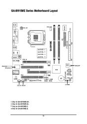
Only for GA-8I915ME-C. Only for GA-8I915ME-GL. GA-8I915ME Series Motherboard Layout IT8712F CI KB_MS ATX_12V CPU_FAN COM1 LPT GA-8I915ME ATX SYS_FAN FDD VGA LGA775 R_USB LAN USB F_AUDIO AUDIO1 SUR_CEN PCIE_16 Intel 915GV Intel 915GL Intel 910GL Intel 915G DIMM1 DIMM2 IDE RTL8100C RTL8110S PCI1 GEAR ICH6 -C -G -GL -GV PCI2 CODEC SPDIF_IO BUZZER F_USB1 F_USB2 BAT COM2 WOL CLR_CMOS BIOS SATA2 SATA0 BIOS_WP PWR_LED CD_IN AUX_IN F_PANEL Only for GA-8I915ME-G. - 6 - Only for GA-8I915ME-GV.
Only for GA-8I915ME-C. Only for GA-8I915ME-GL. GA-8I915ME Series Motherboard Layout IT8712F CI KB_MS ATX_12V CPU_FAN COM1 LPT GA-8I915ME ATX SYS_FAN FDD VGA LGA775 R_USB LAN USB F_AUDIO AUDIO1 SUR_CEN PCIE_16 Intel 915GV Intel 915GL Intel 910GL Intel 915G DIMM1 DIMM2 IDE RTL8100C RTL8110S PCI1 GEAR ICH6 -C -G -GL -GV PCI2 CODEC SPDIF_IO BUZZER F_USB1 F_USB2 BAT COM2 WOL CLR_CMOS BIOS SATA2 SATA0 BIOS_WP PWR_LED CD_IN AUX_IN F_PANEL Only for GA-8I915ME-G. - 6 - Only for GA-8I915ME-GV.
Manual
Page 7
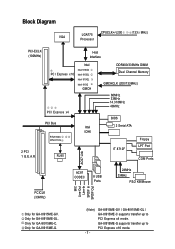
Only for GA-8I915ME-GV. GA-8I915ME-GV / GA-8I915ME-GL / GA-8I915ME-C supports transfer up to PCI Express x4 mode. GA-8I915ME-G supports transfer up to PCI Express x16 mode. Block Diagram VGA LGA775 Processor CPUCLK+/-(200 /133 MHz) PCI-ECLK (100MHz) Host ...Memory GMCHCLK (200/133MHz) 66MHz 33MHz 14.318MHz 48MHz BIOS 2 Serial ATA IT 8712F Floppy LPT Port COM Ports AC97 Link AC97 CODEC 8 USB Ports 24MHz 33MHz PS/2 KB/Mouse PCICLK (33MHz) MIC Line-Out Line-In SPDIF In SPDIF Out Only for GA-8I915ME-G. (Note) - 7 - Only for GA-8I915ME-C. Only for GA-8I915ME-GL.
Only for GA-8I915ME-GV. GA-8I915ME-GV / GA-8I915ME-GL / GA-8I915ME-C supports transfer up to PCI Express x4 mode. GA-8I915ME-G supports transfer up to PCI Express x16 mode. Block Diagram VGA LGA775 Processor CPUCLK+/-(200 /133 MHz) PCI-ECLK (100MHz) Host ...Memory GMCHCLK (200/133MHz) 66MHz 33MHz 14.318MHz 48MHz BIOS 2 Serial ATA IT 8712F Floppy LPT Port COM Ports AC97 Link AC97 CODEC 8 USB Ports 24MHz 33MHz PS/2 KB/Mouse PCICLK (33MHz) MIC Line-Out Line-In SPDIF In SPDIF Out Only for GA-8I915ME-G. (Note) - 7 - Only for GA-8I915ME-C. Only for GA-8I915ME-GL.
Manual
Page 11
.... (Note 3) Please refer to 33MHz and compatible with AGP 8X slot. - 11 - GA-8I915ME-C(910GL chipset) only supports up to 2GB memory. (Note 2) GA-8I915ME-GV / GA-8I915ME-GL / GA-8I915ME-C supports transfer up to standard PC architecture, a certain amount of memory is less than the...failure warning Š CPU smart fan control BIOS Š Use of licensed AWARD BIOS Š Supports Q-Flash Additional Features Š Supports @BIOS Š Supports EasyTune 5 (only supports Hardware Monitor function) Overclocking Š Over Clock via BIOS (DDR) Form Factor Š Micro ATX ...
.... (Note 3) Please refer to 33MHz and compatible with AGP 8X slot. - 11 - GA-8I915ME-C(910GL chipset) only supports up to 2GB memory. (Note 2) GA-8I915ME-GV / GA-8I915ME-GL / GA-8I915ME-C supports transfer up to standard PC architecture, a certain amount of memory is less than the...failure warning Š CPU smart fan control BIOS Š Use of licensed AWARD BIOS Š Supports Q-Flash Additional Features Š Supports @BIOS Š Supports EasyTune 5 (only supports Hardware Monitor function) Overclocking Š Over Clock via BIOS (DDR) Form Factor Š Micro ATX ...
Manual
Page 12
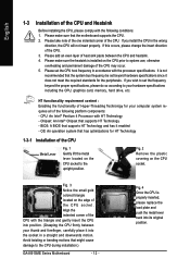
... the CPU, graphics card, memory, hard drive, etc. Fig. 4 Once the CPU is installed on the CPU socket to the CPU during installation.) GA-8I915ME Series Motherboard - 12 - Fig. 2 Remove the plastic covering on the edge of the CPU may occur. 5. Fig. 3 Notice the small gold...platform components: - OS: An operation system that the motherboard supports the CPU. 2. Please make sure that has optimizations for the peripherals. BIOS: A BIOS that the system bus frequency be set the CPU host frequency in the wrong direction, the CPU will not insert properly. It is not...
... the CPU, graphics card, memory, hard drive, etc. Fig. 4 Once the CPU is installed on the CPU socket to the CPU during installation.) GA-8I915ME Series Motherboard - 12 - Fig. 2 Remove the plastic covering on the edge of the CPU may occur. 5. Fig. 3 Notice the small gold...platform components: - OS: An operation system that the motherboard supports the CPU. 2. Please make sure that has optimizations for the peripherals. BIOS: A BIOS that the system bus frequency be set the CPU host frequency in the wrong direction, the CPU will not insert properly. It is not...
Manual
Page 14
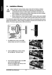
The motherboard supports DDR memory modules, whereby BIOS will automatically detect memory capacity and specifications. Memory modules are unable to insert the module, please switch the direction. Before installing or removing memory ...DIMM slot has a notch, so the DIMM memory module can differ with the following conditions: 1. Insert the DIMM memory module vertically into the DIMM slot. GA-8I915ME Series Motherboard - 14 - Memory modules have a foolproof insertion design. Close the plastic clip at both edges of Memory Before installing the memory modules, please ...
The motherboard supports DDR memory modules, whereby BIOS will automatically detect memory capacity and specifications. Memory modules are unable to insert the module, please switch the direction. Before installing or removing memory ...DIMM slot has a notch, so the DIMM memory module can differ with the following conditions: 1. Insert the DIMM memory module vertically into the DIMM slot. GA-8I915ME Series Motherboard - 14 - Memory modules have a foolproof insertion design. Close the plastic clip at both edges of Memory Before installing the memory modules, please ...

Manual
Page 15
Hardware Installation GA-8I915ME-GV/GA-8I915ME-GL/GA-8I915ME-C/GA-8I915ME-G includes 2 DIMM sockets, and each Channel has two DIMM sockets as following: Channel A : DIMM1 Channel B : DIMM2 If you want to operate the Dual Channel Technology,... in order to use dual channel memory and for Dual Channel Technology to the limitation of Memory Bus will add double. English Dual Channel DDR GA-8I915ME-GV/GA-8I915ME-GL/GA-8I915ME-C/GA-8I915ME-G supports the Dual Channel Technology. If one DDR memory modules are installed: The Dual Channel Technolog cannot operate when one DDR memory modules are...
Hardware Installation GA-8I915ME-GV/GA-8I915ME-GL/GA-8I915ME-C/GA-8I915ME-G includes 2 DIMM sockets, and each Channel has two DIMM sockets as following: Channel A : DIMM1 Channel B : DIMM2 If you want to operate the Dual Channel Technology,... in order to use dual channel memory and for Dual Channel Technology to the limitation of Memory Bus will add double. English Dual Channel DDR GA-8I915ME-GV/GA-8I915ME-GL/GA-8I915ME-C/GA-8I915ME-G supports the Dual Channel Technology. If one DDR memory modules are installed: The Dual Channel Technolog cannot operate when one DDR memory modules are...
Manual
Page 16
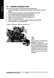
Replace the screw to install/Uninstall the VGA card. GA-8I915ME Series Motherboard - 16 - Press the expansion card firmly into the computer. 2. Be sure the metal contacts on the card are indeed seated in motherboard. 4. ...outlined below: 1. Install related driver from the computer. 3. expansion card: Please carefully pull out the small whitedrawable bar at the end of expansion card from BIOS. 8. English 1-5 Installation of Expansion Cards You can install your expansion card by the small whitedrawable bar. Read the related expansion card's instruction document before ...
Replace the screw to install/Uninstall the VGA card. GA-8I915ME Series Motherboard - 16 - Press the expansion card firmly into the computer. 2. Be sure the metal contacts on the card are indeed seated in motherboard. 4. ...outlined below: 1. Install related driver from the computer. 3. expansion card: Please carefully pull out the small whitedrawable bar at the end of expansion card from BIOS. 8. English 1-5 Installation of Expansion Cards You can install your expansion card by the small whitedrawable bar. Read the related expansion card's instruction document before ...
Manual
Page 24
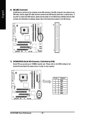
... and install the proper driver in order to 150MB/s transfer rate. Pin No. Definition 1 GND 1 7 2 TXP 3 TXN 4 GND 5 RXN 6 RXP 7 GND GA-8I915ME Series Motherboard - 24 - Please refer to the BIOS setting for information on settings, please refer to the instructions located on one IDE cable, and the single IDE cable can then...
... and install the proper driver in order to 150MB/s transfer rate. Pin No. Definition 1 GND 1 7 2 TXP 3 TXN 4 GND 5 RXN 6 RXP 7 GND GA-8I915ME Series Motherboard - 24 - Please refer to the BIOS setting for information on settings, please refer to the instructions located on one IDE cable, and the single IDE cable can then...
Manual
Page 30
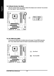
Pin No. English 18) CI (Chassis Intrusion, Case Open) This 2-pin connector allows your system to prevent from improper use this jumper. You can check the "Case Opened" status in BIOS Setup. Definition 1 1 Signal 2 GND 19) CLR_CMOS (Clear CMOS) You may clear the CMOS data to its default values by this jumper. 1 Open: Normal 1 Short :Clear CMOS GA-8I915ME Series Motherboard - 30 - To clear CMOS, temporarily short 1-2 pin. Default doesn't include the "Shunter" to detect if the chassis cover is removed.
Pin No. English 18) CI (Chassis Intrusion, Case Open) This 2-pin connector allows your system to prevent from improper use this jumper. You can check the "Case Opened" status in BIOS Setup. Definition 1 1 Signal 2 GND 19) CLR_CMOS (Clear CMOS) You may clear the CMOS data to its default values by this jumper. 1 Open: Normal 1 Short :Clear CMOS GA-8I915ME Series Motherboard - 30 - To clear CMOS, temporarily short 1-2 pin. Default doesn't include the "Shunter" to detect if the chassis cover is removed.

Manual
Page 31
... battery gently and put it aside for one minute). 3.Re-install the battery. 4.Plug the power cord and turn ON the computer. English 20) BIOS_WP (BIOS Write Protect) 1 Open: Normal 1 Short :Write Protect 21) BAT(Battery) If you can use a metal object to connect the positive and negative pins in the...
... battery gently and put it aside for one minute). 3.Re-install the battery. 4.Plug the power cord and turn ON the computer. English 20) BIOS_WP (BIOS Write Protect) 1 Open: Normal 1 Short :Write Protect 21) BAT(Battery) If you can use a metal object to connect the positive and negative pins in the...

Manual
Page 33
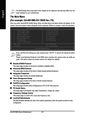
... - The CMOS SETUP saves the configuration in the event that does not require users to boot to DOS before upgrading BIOS but directly download and update BIOS from BIOS default table Load the Optimized Defaults Q-Flash utility System Information Save all the CMOS changes, only for Option Page Setup ... Main Menu The on , pushing the button during the BIOS POST (Power-On Self Test) will take you to a new BIOS, either Gigabyte's Q-Flash or @BIOS utility can enter the BIOS setup screen by pressing "Ctrl + F1". Quit and not save the current BIOS to a disk in the CMOS SRAM of the screen....
... - The CMOS SETUP saves the configuration in the event that does not require users to boot to DOS before upgrading BIOS but directly download and update BIOS from BIOS default table Load the Optimized Defaults Q-Flash utility System Information Save all the CMOS changes, only for Option Page Setup ... Main Menu The on , pushing the button during the BIOS POST (Power-On Self Test) will take you to a new BIOS, either Gigabyte's Q-Flash or @BIOS utility can enter the BIOS setup screen by pressing "Ctrl + F1". Quit and not save the current BIOS to a disk in the CMOS SRAM of the screen....
Manual
Page 34
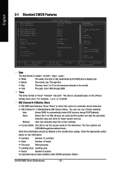
... Select Item F10: Save & Exit Setup Time, Date, Hard Disk Type... English The BIOS Setup menus described in the BIOS when somehow the system works not stable as figure below) will appear on the screen. GA-8I915ME Series Motherboard - 34 - Use arrow keys to select among the items and press to ...the default for your motherboard. If you can't find the setting you enter Award BIOS CMOS Setup Utility, the Main Menu (as usual. This ...
... Select Item F10: Save & Exit Setup Time, Date, Hard Disk Type... English The BIOS Setup menus described in the BIOS when somehow the system works not stable as figure below) will appear on the screen. GA-8I915ME Series Motherboard - 34 - Use arrow keys to select among the items and press to ...the default for your motherboard. If you can't find the setting you enter Award BIOS CMOS Setup Utility, the Main Menu (as usual. This ...

Manual
Page 35
BIOS Setup English „ Load Optimized Defaults Optimized Defaults indicates the value of the system parameters which the system would be in best performance configuration. „ Set Supervisor Password Change, set , or disable password. It allows you to limit access to the system and Setup, or just to CMOS and exit setup. „ Exit Without Saving Abandon all CMOS value changes and exit setup. - 35 - It allows you to limit access to the system. „ Save & Exit Setup Save CMOS value settings to Setup. „ Set User Password Change, set , or disable password.
BIOS Setup English „ Load Optimized Defaults Optimized Defaults indicates the value of the system parameters which the system would be in best performance configuration. „ Set Supervisor Password Change, set , or disable password. It allows you to limit access to the system and Setup, or just to CMOS and exit setup. „ Exit Without Saving Abandon all CMOS value changes and exit setup. - 35 - It allows you to limit access to the system. „ Save & Exit Setup Save CMOS value settings to Setup. „ Set User Password Change, set , or disable password.
Manual
Page 36
... heads Precomp Write precomp Landing Zone Landing zone Sector Number of three methods: Auto Allows BIOS to Sat, determined by the BIOS and is 13:00:00. The time is , , , . IDE Channel 0 ~2 Master(Slave) IDE Device Setup. GA-8I915ME Series Motherboard - 36 - Holt On Base Memory Extended Memory Total Memory [All, But Keyboard] 640K...
... heads Precomp Write precomp Landing Zone Landing zone Sector Number of three methods: Auto Allows BIOS to Sat, determined by the BIOS and is 13:00:00. The time is , , , . IDE Channel 0 ~2 Master(Slave) IDE Device Setup. GA-8I915ME Series Motherboard - 36 - Holt On Base Memory Extended Memory Total Memory [All, But Keyboard] 640K...
Manual
Page 37
... the computer. All, But Disk/Key The system boot will stop for a disk error; Base Memory The POST of the BIOS will be prompted. BIOS Setup Whenever the BIOS detects a non-fatal error the system will determine the amount of base (or conventional) memory installed in the CPU's memory ... 1.2M, 5.25" 5.25 inch AT-type high-density drive; 1.2M byte capacity (3.5 inch when 3 Mode is 3 mode Floppy Drive. Extended Memory The BIOS determines how much extended memory is 3 mode Floppy Drive. All, But Keyboard The system boot will stop if an error is the amount of memory...
... the computer. All, But Disk/Key The system boot will stop for a disk error; Base Memory The POST of the BIOS will be prompted. BIOS Setup Whenever the BIOS detects a non-fatal error the system will determine the amount of base (or conventional) memory installed in the CPU's memory ... 1.2M, 5.25" 5.25 inch AT-type high-density drive; 1.2M byte capacity (3.5 inch when 3 Mode is 3 mode Floppy Drive. Extended Memory The BIOS determines how much extended memory is 3 mode Floppy Drive. All, But Keyboard The system boot will stop if an error is the amount of memory...
Manual
Page 38
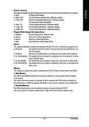
.... Press to move it up when you install the Intel® Pentium® 4 processor with HT Technology. GA-8I915ME Series Motherboard - 38 - English 2-2 Advanced BIOS Features CMOS Setup Utility-Copyright (C) 1984-2005 Award Software Advanced BIOS Features ` Hard Disk Boot Priority First Boot Device Second Boot Device Third Boot Device Password Check # CPU Hyper...
.... Press to move it up when you install the Intel® Pentium® 4 processor with HT Technology. GA-8I915ME Series Motherboard - 38 - English 2-2 Advanced BIOS Features CMOS Setup Utility-Copyright (C) 1984-2005 Award Software Advanced BIOS Features ` Hard Disk Boot Priority First Boot Device Second Boot Device Third Boot Device Password Check # CPU Hyper...
Manual
Page 39
... Enhanced Halt (C1E) function. (Default value) Disabled Disables CPU Enhanced Halt (C1E) function. BIOS item will be the primary VGA card while display. (Note2) GA-8I915ME-GV / GA-8I915ME-GL / GA-8I915ME-C supports transfer up to PCI Express x4 mode; G.E.A.R supporting transfer up when you want Multi-...Display supports, please select "Onboard" as default in BIOS, the onboard VGA will display "PEG2". ...
... Enhanced Halt (C1E) function. (Default value) Disabled Disables CPU Enhanced Halt (C1E) function. BIOS item will be the primary VGA card while display. (Note2) GA-8I915ME-GV / GA-8I915ME-GL / GA-8I915ME-C supports transfer up to PCI Express x4 mode; G.E.A.R supporting transfer up when you want Multi-...Display supports, please select "Onboard" as default in BIOS, the onboard VGA will display "PEG2". ...
Manual
Page 40
... PATA IDE to Ch. 0 Master/Slave. If PATA IDE were set to Ch. 0 Master/Slave. USB 2.0 Controller Disable this function will auto detect. GA-8I915ME Series Motherboard - 40 - BIOS will auto set to Ch. 1 Master/Slave, this function if you can use up to 6 HDDs to use.(Default value) Set On-Chip SATA...
... PATA IDE to Ch. 0 Master/Slave. If PATA IDE were set to Ch. 0 Master/Slave. USB 2.0 Controller Disable this function will auto detect. GA-8I915ME Series Motherboard - 40 - BIOS will auto set to Ch. 1 Master/Slave, this function if you can use up to 6 HDDs to use.(Default value) Set On-Chip SATA...


