
Manual
Page 4
...11 1-3-1 Installation of the CPU 11 1-3-2 Installation of the Heatsink 12 1-4 Installation of Memory 13 1-5 Installation of Expansion Cards 15 1-6 I/O Back Panel Introduction 16 1-7 Connectors Introduction 17 Chapter 2 BIOS Setup 27 The Main Menu (For example: BIOS Ver. : E2 28 2-1 Standard CMOS Features 30 2-2 Advanced BIOS Features 32 2-3 Integrated Peripherals 34 2-4 Power ManagementSetup 37 2-5 PnP/PCI Configurations 38 2-6 PC Health Status 39 2-7 Frequency/Voltage Control 40 2-8 Load Fail-Safe Defaults 41 2-9 Load Optimized Defaults 41 2-10 SetSupervisor/User Password 42...
...11 1-3-1 Installation of the CPU 11 1-3-2 Installation of the Heatsink 12 1-4 Installation of Memory 13 1-5 Installation of Expansion Cards 15 1-6 I/O Back Panel Introduction 16 1-7 Connectors Introduction 17 Chapter 2 BIOS Setup 27 The Main Menu (For example: BIOS Ver. : E2 28 2-1 Standard CMOS Features 30 2-2 Advanced BIOS Features 32 2-3 Integrated Peripherals 34 2-4 Power ManagementSetup 37 2-5 PnP/PCI Configurations 38 2-6 PC Health Status 39 2-7 Frequency/Voltage Control 40 2-8 Load Fail-Safe Defaults 41 2-9 Load Optimized Defaults 41 2-10 SetSupervisor/User Password 42...
Manual
Page 10
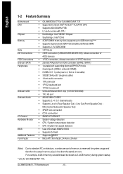
... 2 serial ports (COMA, onboard COMB) w 8 USB 2.0/1.1 ports (rear x 4, front x 4 via cable) w 3 IEEE1394 ports* (requires cable) w 1 front audio connector w 1 IR connector w 1 PS/2 keyboard port w 1 PS/2 mouse port w Onboard Marvell 8001 chip (10/100/1000 Mbit) w 1 RJ 45 port w ADI AD1888 CODEC w Supports 2 / 4 / 5.1 channel audio w Supports Line In (Rear Speaker Out) ; GA-8I865GVM(F)-775 Motherboard - 10 - English 1-2 Feature Summary M otherboard CPU Chip set Mem ory Slo ts IDE Connections FDD Connections Onboard SATA Peripherals Onboard LAN Onboard Audio I/O Control Hardware Monitor BIOS...
... 2 serial ports (COMA, onboard COMB) w 8 USB 2.0/1.1 ports (rear x 4, front x 4 via cable) w 3 IEEE1394 ports* (requires cable) w 1 front audio connector w 1 IR connector w 1 PS/2 keyboard port w 1 PS/2 mouse port w Onboard Marvell 8001 chip (10/100/1000 Mbit) w 1 RJ 45 port w ADI AD1888 CODEC w Supports 2 / 4 / 5.1 channel audio w Supports Line In (Rear Speaker Out) ; GA-8I865GVM(F)-775 Motherboard - 10 - English 1-2 Feature Summary M otherboard CPU Chip set Mem ory Slo ts IDE Connections FDD Connections Onboard SATA Peripherals Onboard LAN Onboard Audio I/O Control Hardware Monitor BIOS...
Manual
Page 20
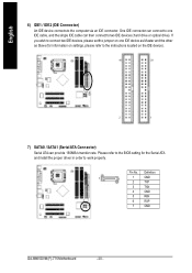
... GA-8I865GVM(F)-775 Motherboard - 20 - If you wish to connect two IDE devices, please set the jumper on one IDE cable, and the single IDE cable can provide 150MB/s transfer rate. Pin No. English 6) IDE1 / IDE2 (IDE Connector) An IDE device connects to two IDE devices ( hard drive or optical drive). One IDE connector can connect to one IDE device as Master and the other as Slave (for the Serial ATA and install the proper driver in order to the instructions located on the IDE device...
... GA-8I865GVM(F)-775 Motherboard - 20 - If you wish to connect two IDE devices, please set the jumper on one IDE cable, and the single IDE cable can provide 150MB/s transfer rate. Pin No. English 6) IDE1 / IDE2 (IDE Connector) An IDE device connects to two IDE devices ( hard drive or optical drive). One IDE connector can connect to one IDE device as Master and the other as Slave (for the Serial ATA and install the proper driver in order to the instructions located on the IDE device...
Manual
Page 22
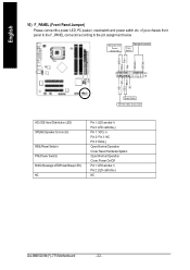
...:Normal Operation Close: Reset Hardware System Open:Normal Operation Close:Power On/Off Pin 1: LED anode(+) Pin 2: LED cathode(-) NC GA-8I865GVM(F)-775 Motherboard - 22 - PW+ PWSPEAK+ SPEAK- 2 20 1 19 HD+ HD- English 10) F_PANEL (Front Panel Jumper) Please connect the power LED, PC peaker, reset switch and power switch etc. RESRES+ NC Re set Switch ID E Har d Disk Active L ED HD (IDE Hard Disk Active LED) SPEAK(Speaker Connector) RES (Reset Switch) PW(Power Switch) MSG (Message LED/Power/Sleep LED) NC Pin 1: LED anode(+) Pin 2: LED cathode(-) Pin 1: VCC(+) Pin 2-
...:Normal Operation Close: Reset Hardware System Open:Normal Operation Close:Power On/Off Pin 1: LED anode(+) Pin 2: LED cathode(-) NC GA-8I865GVM(F)-775 Motherboard - 22 - PW+ PWSPEAK+ SPEAK- 2 20 1 19 HD+ HD- English 10) F_PANEL (Front Panel Jumper) Please connect the power LED, PC peaker, reset switch and power switch etc. RESRES+ NC Re set Switch ID E Har d Disk Active L ED HD (IDE Hard Disk Active LED) SPEAK(Speaker Connector) RES (Reset Switch) PW(Power Switch) MSG (Message LED/Power/Sleep LED) NC Pin 1: LED anode(+) Pin 2: LED cathode(-) Pin 1: VCC(+) Pin 2-
Manual
Page 24
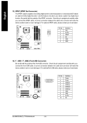
... you connect the SPDIF cable, incorrect connection between the cable and connector will make the device unable to an external Dolby Digital Decoder. Pin No. Definition 1 Power 2 1 10 2 Power 9 3 USB Dx- 4 USB Dy- 5 USB Dx+ 6 USB Dy+ 7 GND 8 GND 9 No Pin 10 NC GA-8I865GVM(F)-775 Motherboard - 24 - Definition 65 1 VCC 2 No Pin 3 SPDIF 21 4 NC 5 GND 6 GND 14) F_ USB1 / F_USB2 (Front USB Connector) Be careful with the polarity of the SPDIF connector. For optional SPDIF cable...
... you connect the SPDIF cable, incorrect connection between the cable and connector will make the device unable to an external Dolby Digital Decoder. Pin No. Definition 1 Power 2 1 10 2 Power 9 3 USB Dx- 4 USB Dy- 5 USB Dx+ 6 USB Dy+ 7 GND 8 GND 9 No Pin 10 NC GA-8I865GVM(F)-775 Motherboard - 24 - Definition 65 1 VCC 2 No Pin 3 SPDIF 21 4 NC 5 GND 6 GND 14) F_ USB1 / F_USB2 (Front USB Connector) Be careful with the polarity of the SPDIF connector. For optional SPDIF cable...
Manual
Page 28
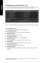
... safe configu ration. English The Main Menu (For example: BIOS Ver. : E2) Oncey ou enter Aw ard BIOS CMOSSetup Utility, the Main Menu (as figure below ) w illappear on the screen. n Frequency/ Voltage Control This setup page is the Sy stem auto detect Temperature, v oltage, fan, speed. Use arrow key s to select among the items and press to searchthe adv anced option hidden. Flash Load Fail-Safe Defaults Load Optimized Defaults SetSu pervisor Pa ssword SetUser Password Save & Exit Setup...
... safe configu ration. English The Main Menu (For example: BIOS Ver. : E2) Oncey ou enter Aw ard BIOS CMOSSetup Utility, the Main Menu (as figure below ) w illappear on the screen. n Frequency/ Voltage Control This setup page is the Sy stem auto detect Temperature, v oltage, fan, speed. Use arrow key s to select among the items and press to searchthe adv anced option hidden. Flash Load Fail-Safe Defaults Load Optimized Defaults SetSu pervisor Pa ssword SetUser Password Save & Exit Setup...
Manual
Page 30
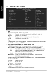
...:00. GA-8I865GVM(F)- 775 Motherboard - 30 - You can manually input the correct settings. Through Dec. timeclock. English 2-1 Standard CMOS Features Date(mm:dd:y y ) Tim e (hh:m m :ss) CMOS Setup Utility -Cop y right (C) 198 4-2004 Award Software Stan dard CM OS Features Thu, Au g 5 2004 22:3 1:24 Item Help Menu Level} } IDE Channel 0 M aster } IDE Channel 0 Slave } IDE Channel 1 M aster } IDE Channel 1 Slave Drive A Driv e B Flopp y 3 Mode Suport [None] [None] [None] [None] [1.44M, 3.5"] [None] [Disabled] Change the...
...:00. GA-8I865GVM(F)- 775 Motherboard - 30 - You can manually input the correct settings. Through Dec. timeclock. English 2-1 Standard CMOS Features Date(mm:dd:y y ) Tim e (hh:m m :ss) CMOS Setup Utility -Cop y right (C) 198 4-2004 Award Software Stan dard CM OS Features Thu, Au g 5 2004 22:3 1:24 Item Help Menu Level} } IDE Channel 0 M aster } IDE Channel 0 Slave } IDE Channel 1 M aster } IDE Channel 1 Slave Drive A Driv e B Flopp y 3 Mode Suport [None] [None] [None] [None] [1.44M, 3.5"] [None] [Disabled] Change the...
Manual
Page 32
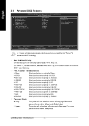
...; 4 processor w ithHT Technology. LS120 Selecty our boot dev ice priority by USB-FDD. USB-FDD Selecty our bootdev ice priority by LS120. USB- LAN Select y our boot dev ice priority by Floppy . to ex it down the list. English 2-2 Advanced BIOS Features CMOS Setup Utility -Cop y right (C) 198 4-2004 Award Software Advanc ed BIOSFe atures } Hard Disk Bo otPrio rity First Boot De vice Second Bo ot Device [Press Enter] [Floppy ] [Hard Disk] Item...
...; 4 processor w ithHT Technology. LS120 Selecty our boot dev ice priority by USB-FDD. USB-FDD Selecty our bootdev ice priority by LS120. USB- LAN Select y our boot dev ice priority by Floppy . to ex it down the list. English 2-2 Advanced BIOS Features CMOS Setup Utility -Cop y right (C) 198 4-2004 Award Software Advanc ed BIOSFe atures } Hard Disk Bo otPrio rity First Boot De vice Second Bo ot Device [Press Enter] [Floppy ] [Hard Disk] Item...

Manual
Page 34
... PCI IDE Enab led Enable onboard 1st channel IDE port. (Default v alue) Disabled Disable onboard 1st channel IDE port. English 2-3 Integrated Peripherals CMOS Setup Utility -Cop y right (C) 198 4-2004 Award Software IntegratedPeripherals On-Chip Primary PCI IDE On-Chip Secon dary PCI IDE On-Chip SATA x SATA P ort0 config ure as SATA P ort1 config ure as " item. * Only for GA-8I865GVMF-775. GA-8I865GVM(F)- 775 Motherboard - 34 - On-Chip Secondary P CI IDE Enab led Enable onboard 2nd channel IDE port. (Default v alue) Disabled Disable onboard 2nd channel IDE port. On-Chi p SATA...
... PCI IDE Enab led Enable onboard 1st channel IDE port. (Default v alue) Disabled Disable onboard 1st channel IDE port. English 2-3 Integrated Peripherals CMOS Setup Utility -Cop y right (C) 198 4-2004 Award Software IntegratedPeripherals On-Chip Primary PCI IDE On-Chip Secon dary PCI IDE On-Chip SATA x SATA P ort0 config ure as SATA P ort1 config ure as " item. * Only for GA-8I865GVMF-775. GA-8I865GVM(F)- 775 Motherboard - 34 - On-Chip Secondary P CI IDE Enab led Enable onboard 2nd channel IDE port. (Default v alue) Disabled Disable onboard 2nd channel IDE port. On-Chi p SATA...

Manual
Page 35
...Keyboard Support Enab led Disabled EnableUSB key board support. Onboard H/W 1394* Enab led Disabled Enable onboard IEEE1394 function. (Default v alue) Disable thi s function. Slav e Set SATA controller to IDE Secondary Master. IDE Sec. SATA Port 0). This mode SATA Port1 is only supported by Window s XP orlater. (Default v alue) Set SATA controller tonativ e mode(Serial ATA mode - USB 2.0 Controller You can disable this function. (Default v alue) * Only for GA-8I865GVMF-775. - 35 - BIOS Setup Slav e Set SATA controller to inv oke the boot ROM of the onboard LAN...
...Keyboard Support Enab led Disabled EnableUSB key board support. Onboard H/W 1394* Enab led Disabled Enable onboard IEEE1394 function. (Default v alue) Disable thi s function. Slav e Set SATA controller to IDE Secondary Master. IDE Sec. SATA Port 0). This mode SATA Port1 is only supported by Window s XP orlater. (Default v alue) Set SATA controller tonativ e mode(Serial ATA mode - USB 2.0 Controller You can disable this function. (Default v alue) * Only for GA-8I865GVMF-775. - 35 - BIOS Setup Slav e Set SATA controller to inv oke the boot ROM of the onboard LAN...
Manual
Page 37
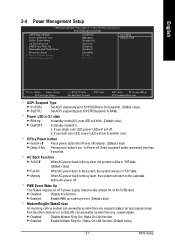
...). (Default v alue) S3(STR) Set ACPI suspend ty pe to S3/STR(Suspend ToRAM). Enter suspendif button is pressed less than 4 seconds. PME Event Wake Up This feature requires an ATX power supply that prov ides at least 1A on theLAN can aw akethe sy stem from any suspend state or an input signalcomes from any suspendstate. BIOS Setup b. to another color. Disabled Disable...
...). (Default v alue) S3(STR) Set ACPI suspend ty pe to S3/STR(Suspend ToRAM). Enter suspendif button is pressed less than 4 seconds. PME Event Wake Up This feature requires an ATX power supply that prov ides at least 1A on theLAN can aw akethe sy stem from any suspend state or an input signalcomes from any suspendstate. BIOS Setup b. to another color. Disabled Disable...
Manual
Page 53
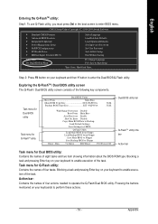
...Language Load Fail-Safe Defaults Load Optimized Defaults Set Supervisor Password Set User Password Save & Exit Setup Exit Without Saving ESC: Quit F8: Dual BIOS/Q-Flash F3: Change Language F10: Save & Exit Setup Time, Date, Hard Disk Type... Task menu for Dual BIOS utility Task menu for Q-FlashTM utility Dual BIOS Utility Boot From Main Bios Main ROM Type/Size SST 49LF003A Backup ROM Type/Size SST 49LF003A 512K 512K Wide Range Protection Disable Boot From Main Bios Auto Recovery Enable Halt On Error Disable Copy Main ROM Data to Backup Load Default Settings Save Settings to CMOS Enter...
...Language Load Fail-Safe Defaults Load Optimized Defaults Set Supervisor Password Set User Password Save & Exit Setup Exit Without Saving ESC: Quit F8: Dual BIOS/Q-Flash F3: Change Language F10: Save & Exit Setup Time, Date, Hard Disk Type... Task menu for Dual BIOS utility Task menu for Q-FlashTM utility Dual BIOS Utility Boot From Main Bios Main ROM Type/Size SST 49LF003A Backup ROM Type/Size SST 49LF003A 512K 512K Wide Range Protection Disable Boot From Main Bios Auto Recovery Enable Halt On Error Disable Copy Main ROM Data to Backup Load Default Settings Save Settings to CMOS Enter...
Manual
Page 54
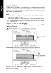
... listed. Dual BIOS Utility Boot From Main Bios Main ROM Type/Size SST 49LF003A Backup ROM Type/Size SST 49LF003A 512K 512K Wide Range Protection Disable R>>ea>d>i>ng>>B>IAO>Hu>Sat>olfBt>ilRoOe>oe>nftcr.ooF.E.vmr.r.oer.o.mrf.yl.ro..p..p.MED.y.n.ia.s.a.i.a.nb..blBeleios Copy Main ROM Data to Backup Don't Turn Off PoLwoeardoDreRfaeuslettSSeytstitnegms Save Settings to CMOS Enter : Run Q-Flash Utility Load Main BIOS from Floppy Load Backup BIOS from the floppy disk. GA-8I865GVM(F)-775 Motherboard - 54 - As described in the Q-Flash menu and...
... listed. Dual BIOS Utility Boot From Main Bios Main ROM Type/Size SST 49LF003A Backup ROM Type/Size SST 49LF003A 512K 512K Wide Range Protection Disable R>>ea>d>i>ng>>B>IAO>Hu>Sat>olfBt>ilRoOe>oe>nftcr.ooF.E.vmr.r.oer.o.mrf.yl.ro..p..p.MED.y.n.ia.s.a.i.a.nb..blBeleios Copy Main ROM Data to Backup Don't Turn Off PoLwoeardoDreRfaeuslettSSeytstitnegms Save Settings to CMOS Enter : Run Q-Flash Utility Load Main BIOS from Floppy Load Backup BIOS from the floppy disk. GA-8I865GVM(F)-775 Motherboard - 54 - As described in the Q-Flash menu and...

Manual
Page 55
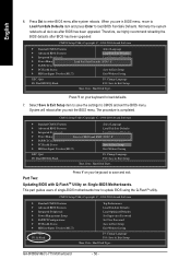
... flashed. Dual BIOS Utility Boot From Main Bios Main ROM Type/Size SST 49LF003A Backup ROM Type/Size SST 49LF003A 512K 512K Wide Range Protection Disable Boot From Main Bios AutoARreecyoovuesryure EtonaRbEleSET ? Halt On Error Disable [ECntoepry] tMoacionnRtiOnuMreDoarta[EtosBc]actokuapbort... Then it begins flashing BIOS. 4. Press any keys to return to Floppy hi:Move ESC:Reset F10:Power Off After system reboots, you may find the BIOS version on your boot screen becomes the one you exit Q-Flash. Pass !! Load Default Settings Save Settings to CMOS Enter...
... flashed. Dual BIOS Utility Boot From Main Bios Main ROM Type/Size SST 49LF003A Backup ROM Type/Size SST 49LF003A 512K 512K Wide Range Protection Disable Boot From Main Bios AutoARreecyoovuesryure EtonaRbEleSET ? Halt On Error Disable [ECntoepry] tMoacionnRtiOnuMreDoarta[EtosBc]actokuapbort... Then it begins flashing BIOS. 4. Press any keys to return to Floppy hi:Move ESC:Reset F10:Power Off After system reboots, you may find the BIOS version on your boot screen becomes the one you exit Q-Flash. Pass !! Load Default Settings Save Settings to CMOS Enter...
Manual
Page 56
... exit the BIOS menu. Part Two: Updating BIOS with Q-FlashTM Utility on your keyboard to save the settings to load BIOS Fail-Safe Defaults. This part guides users of single-BIOS motherboards how to CMOS and EXIT (SYe/tNS)u?pYervisor Password } PnP/PCI Configurations Set User Password } PC Health Status Save & Exit Setup } MB Intelligent Tweaker(M.I.T.) Exit Without Saving ESC: Quit F8: Dual BIOS/Q-Flash F3: Change Language F10: Save & Exit Setup Time, Date, Hard Disk Type... CMOS Setup Utility-Copyright (C) 1984-2004 Award Software } Standard CMOS Features Select...
... exit the BIOS menu. Part Two: Updating BIOS with Q-FlashTM Utility on your keyboard to save the settings to load BIOS Fail-Safe Defaults. This part guides users of single-BIOS motherboards how to CMOS and EXIT (SYe/tNS)u?pYervisor Password } PnP/PCI Configurations Set User Password } PC Health Status Save & Exit Setup } MB Intelligent Tweaker(M.I.T.) Exit Without Saving ESC: Quit F8: Dual BIOS/Q-Flash F3: Change Language F10: Save & Exit Setup Time, Date, Hard Disk Type... CMOS Setup Utility-Copyright (C) 1984-2004 Award Software } Standard CMOS Features Select...
Manual
Page 59
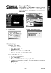
... @BIOS utility Click "P" Click "Update New BIOS" Fig 4. Click "Update New BIOS" c. Fig 1. Methods and steps: I. Select the exact model name on your motherboard e. Installation complete and run @BIOS Select @BIOS item. d. Select the desired @BIOS server 1. Just select the desired @BIOS server to update their BIOS under Windows. Click "Internet Update" icon b. II. Please search for BIOS unzip file, downloading from internet or any other methods (such as: 8I865GVM-775.E2). Update BIOS...
... @BIOS utility Click "P" Click "Update New BIOS" Fig 4. Click "Update New BIOS" c. Fig 1. Methods and steps: I. Select the exact model name on your motherboard e. Installation complete and run @BIOS Select @BIOS item. d. Select the desired @BIOS server 1. Just select the desired @BIOS server to update their BIOS under Windows. Click "Internet Update" icon b. II. Please search for BIOS unzip file, downloading from internet or any other methods (such as: 8I865GVM-775.E2). Update BIOS...
Manual
Page 62
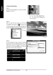
... "Preferences" menu, click the "Listening Environment" tab. In the "Speaker Setup" box, click "Multi-drive" and then click "Apply". Right-click the icon to "Line In". You will find a multi-driver icon on the lower right of the screen. GA-8I865GVM(F)-775 Motherboard - 62 - This completes the 4-channel audio configuration. English 4 Channel Audio Setup STEP 1 : Connect the Front Speakers to "Line Out", the Rear Speakers to select "SoundMAX Control Panel" or...
... "Preferences" menu, click the "Listening Environment" tab. In the "Speaker Setup" box, click "Multi-drive" and then click "Apply". Right-click the icon to "Line In". You will find a multi-driver icon on the lower right of the screen. GA-8I865GVM(F)-775 Motherboard - 62 - This completes the 4-channel audio configuration. English 4 Channel Audio Setup STEP 1 : Connect the Front Speakers to "Line Out", the Rear Speakers to select "SoundMAX Control Panel" or...
Manual
Page 63
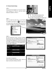
... select "SoundMAX Control Panel" or "Preferences". Right-click the icon to "MIC In". This completes the 5.1 channel audio configuration. STEP 2 : After you install the audio driver, you will find the "SoundMAX Control Panel" icon in the status area on the SoundMAX menu. In the "Speaker Setup" box, click "Surround Sound Speakers (5.1 Surround)" and then click "Apply". Sound Effect Configuration: At the "Acoustic Environments" menu, users can adjust sound option settings as desired...
... select "SoundMAX Control Panel" or "Preferences". Right-click the icon to "MIC In". This completes the 5.1 channel audio configuration. STEP 2 : After you install the audio driver, you will find the "SoundMAX Control Panel" icon in the status area on the SoundMAX menu. In the "Speaker Setup" box, click "Surround Sound Speakers (5.1 Surround)" and then click "Apply". Sound Effect Configuration: At the "Acoustic Environments" menu, users can adjust sound option settings as desired...

Manual
Page 65
... after entering BIOS menu and you can use all , you don't need to clear CMOS. Turn off the on the MB chipset. Question 6: Why does system seem unstable after it at http://tw.giga-byte.com/support/user_pdf/raid_manual.pdf) Question 5: How do I use a metal object to connect the positive and negative pins in the CD-ROM to a floppy disk before installing drivers. Answer: If your board doesn't have such jumper...
... after entering BIOS menu and you can use all , you don't need to clear CMOS. Turn off the on the MB chipset. Question 6: Why does system seem unstable after it at http://tw.giga-byte.com/support/user_pdf/raid_manual.pdf) Question 5: How do I use a metal object to connect the positive and negative pins in the CD-ROM to a floppy disk before installing drivers. Answer: If your board doesn't have such jumper...

Manual
Page 66
... 11 beeps Cache memory bad AWARD BIOS Beep Codes 1 short: System boots successfully 2 short: CMOS setting error 1 long 1 short: DRAM or M/B error 1 long 2 short: Monitor or display card error 1 long 3 short: Keyboard error 1 long 9 short: BIOS ROM error Continuous long beeps: DRAM error Continuous short beeps: Power error Question 11:For the M/B which have connected any of your own cables to bootup from case to set in RAID/ SCSI BIOS. Integrated Peripherals--> Onboard H/W ATA/RAID: "enable" Then it depends on the mode(RAID or ATA) that you identify the possible computer problems...
... 11 beeps Cache memory bad AWARD BIOS Beep Codes 1 short: System boots successfully 2 short: CMOS setting error 1 long 1 short: DRAM or M/B error 1 long 2 short: Monitor or display card error 1 long 3 short: Keyboard error 1 long 9 short: BIOS ROM error Continuous long beeps: DRAM error Continuous short beeps: Power error Question 11:For the M/B which have connected any of your own cables to bootup from case to set in RAID/ SCSI BIOS. Integrated Peripherals--> Onboard H/W ATA/RAID: "enable" Then it depends on the mode(RAID or ATA) that you identify the possible computer problems...


