Manual
Page 4
Table of Contents GA-8I865GMFK-775/GA-8I865GMK-775 Motherboard Layout 6 Block Diagram ...7 Chapter 1 Hardware Installation 9 1-1 Considerations Prior to Installation 9 1-2 Feature Summary 10 1-3 Installation of the CPU and Heatsink 12 1-3-1 Installation of the CPU 12 1-3-2 Installation of the Heatsink 13 1-4 Installation of Memory 14 1-5 Installation of Expansion Cards 16 1-6 I/O Back Panel Introduction 17 1-7 Connectors Introduction 18 Chapter 2 BIOS...
Table of Contents GA-8I865GMFK-775/GA-8I865GMK-775 Motherboard Layout 6 Block Diagram ...7 Chapter 1 Hardware Installation 9 1-1 Considerations Prior to Installation 9 1-2 Feature Summary 10 1-3 Installation of the CPU and Heatsink 12 1-3-1 Installation of the CPU 12 1-3-2 Installation of the Heatsink 13 1-4 Installation of Memory 14 1-5 Installation of Expansion Cards 16 1-6 I/O Back Panel Introduction 17 1-7 Connectors Introduction 18 Chapter 2 BIOS...
Manual
Page 9
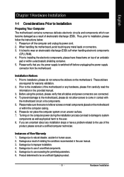
...Prior to installing the electronic components, please have a problem related to wear an electrostatic discharge (ESD) cuff when handling electronic components (CPU, RAM). 4. Instances of the product, please consult a certified computer technician. Prior to the installation of uncertified components. 5. Before ...please verify that you are connected. 4. Please make sure there are required for warranty validation. 2. Damage due to be an unofficial Gigabyte product. - 9 - Product determined to use of the motherboard or any metal leads or connectors. 3. It is switched off the...
...Prior to installing the electronic components, please have a problem related to wear an electrostatic discharge (ESD) cuff when handling electronic components (CPU, RAM). 4. Instances of the product, please consult a certified computer technician. Prior to the installation of uncertified components. 5. Before ...please verify that you are connected. 4. Please make sure there are required for warranty validation. 2. Damage due to be an unofficial Gigabyte product. - 9 - Product determined to use of the motherboard or any metal leads or connectors. 3. It is switched off the...
Manual
Page 10
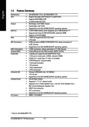
... FDD Connections Onboard SATA Peripherals Onboard LAN Onboard Audio I/O Control Š GA-8I865GMK-775 or GA-8I865GMFK-775 Š Supports the latest Intel® Pentium® 4 LGA775 CPU Š Supports 800/533MHz FSB Š L2 cache varies with CPU Š Northbridge: Intel® 865G Chipset Š Southbridge: Intel®...100Mbit) Š 1 RJ 45 port Š Supported on the Win 98/ME2000/XP operating systems Š SMSC LPC47M997 * Only for GA-8I865GMFK-775. MIC (Center/Subwoofer Speaker Out) Š SPDIF Out connection Š CD In connection Š Supported on the Win 98/ME/2000/...
... FDD Connections Onboard SATA Peripherals Onboard LAN Onboard Audio I/O Control Š GA-8I865GMK-775 or GA-8I865GMFK-775 Š Supports the latest Intel® Pentium® 4 LGA775 CPU Š Supports 800/533MHz FSB Š L2 cache varies with CPU Š Northbridge: Intel® 865G Chipset Š Southbridge: Intel®...100Mbit) Š 1 RJ 45 port Š Supported on the Win 98/ME2000/XP operating systems Š SMSC LPC47M997 * Only for GA-8I865GMFK-775. MIC (Center/Subwoofer Speaker Out) Š SPDIF Out connection Š CD In connection Š Supported on the Win 98/ME/2000/...
Manual
Page 11
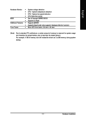
English Hardware Monitor Š System voltage detection Š CPU / System temperature detection Š CPU / System fan speed detection Š CPU Smart fan control BIOS Š Use of licensed AWARD BIOS Š Supports Q-Flash Additional Features Š Supports @BIOS Š Supports EasyTune5 (only supports Hardware Monitor ...
English Hardware Monitor Š System voltage detection Š CPU / System temperature detection Š CPU / System fan speed detection Š CPU Smart fan control BIOS Š Use of licensed AWARD BIOS Š Supports Q-Flash Additional Features Š Supports @BIOS Š Supports EasyTune5 (only supports Hardware Monitor ...
Manual
Page 12
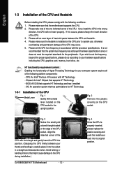
... frequency in a straight and downwards motion. BIOS: A BIOS that the motherboard supports the CPU. 2. Avoid twisting or bending motions that supports HT Technology - If you wish to the CPU during installation.) GA-8I865GM(F)K-775 Motherboard - 12 - CPU: An Intel® Pentium 4 Processor with the processor specifications. HT functionality requirement content : Enabling the functionality of the...
... frequency in a straight and downwards motion. BIOS: A BIOS that the motherboard supports the CPU. 2. Avoid twisting or bending motions that supports HT Technology - If you wish to the CPU during installation.) GA-8I865GM(F)K-775 Motherboard - 12 - CPU: An Intel® Pentium 4 Processor with the processor specifications. HT functionality requirement content : Enabling the functionality of the...
Manual
Page 13
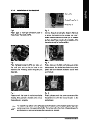
... Push Pin Female Push Pin Fig.1 Please apply an even layer of heatsink paste on the surface of the heatsink to the CPU fan header located on the motherboard. If the push pin is complete. Fig. 6 Finally, please attach the power connector of the installed...dissipation or using extreme care when removing the heatsink. - 13 - Hardware Installation Pressing down the push pins diagonally. The heatsink may adhere to the CPU as the picture, the installation is inserted as a result of hardening of motherboard after installing. Fig. 4 Please make sure the push pins aim to...
... Push Pin Female Push Pin Fig.1 Please apply an even layer of heatsink paste on the surface of the heatsink to the CPU fan header located on the motherboard. If the push pin is complete. Fig. 6 Finally, please attach the power connector of the installed...dissipation or using extreme care when removing the heatsink. - 13 - Hardware Installation Pressing down the push pins diagonally. The heatsink may adhere to the CPU as the picture, the installation is inserted as a result of hardening of motherboard after installing. Fig. 4 Please make sure the push pins aim to...

Manual
Page 19
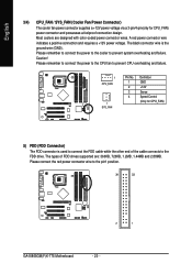
... power to start . Please use of the power connector, the power supply can lead to an unstable system or a system that is unable to the CPU. Align the power connector with its proper location on the motherboard before plugging in while the ATX power supplier is used (300W or greater). Otherwise...
... power to start . Please use of the power connector, the power supply can lead to an unstable system or a system that is unable to the CPU. Align the power connector with its proper location on the motherboard before plugging in while the ATX power supplier is used (300W or greater). Otherwise...
Manual
Page 20
... ground wire (GND). Please remember to connect the power to the cooler to the FDD drive. Please remember to connect the power to the CPU fan to prevent CPU overheating and failure. 1 CPU_FAN 1 SYS_FAN Pin No. 1 2 3 4 Definition GND +12V Sense Speed Control (Only for CPU_FAN) power connector and possesses a ...red power connector wire indicates a positive connection and requires a +12V power voltage. Please connect the red power connector wire to the pin1 position. 34 33 2 1 GA-8I865GM(F)K-775 Motherboard - 20 - Most coolers are : 360KB, 720KB, 1.2MB, 1.44MB and 2.88MB.
... ground wire (GND). Please remember to connect the power to the cooler to the FDD drive. Please remember to connect the power to the CPU fan to prevent CPU overheating and failure. 1 CPU_FAN 1 SYS_FAN Pin No. 1 2 3 4 Definition GND +12V Sense Speed Control (Only for CPU_FAN) power connector and possesses a ...red power connector wire indicates a positive connection and requires a +12V power voltage. Please connect the red power connector wire to the pin1 position. 34 33 2 1 GA-8I865GM(F)K-775 Motherboard - 20 - Most coolers are : 360KB, 720KB, 1.2MB, 1.44MB and 2.88MB.
Manual
Page 30
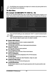
...Status This setup page is the System auto detect Temperature, voltage, fan, speed. „ Frequency/Voltage Control This setup page is control CPU clock and frequency ratio. „ Load Fail-Safe Defaults Fail-Safe Defaults indicates the value of the system parameters which the system would be...Save & Exit Setup Exit Without Saving KLJI: Select Item F10: Save & Exit Setup Time, Date, Hard Disk Type... GA-8I865GM(F)K-775 Motherboard - 30 - The Main Menu (For example: GA-8I865GMFK-775 / BIOS Ver. : E2) Once you want, please press "Ctrl+F1" to accept or enter the sub-menu. Please...
...Status This setup page is the System auto detect Temperature, voltage, fan, speed. „ Frequency/Voltage Control This setup page is control CPU clock and frequency ratio. „ Load Fail-Safe Defaults Fail-Safe Defaults indicates the value of the system parameters which the system would be...Save & Exit Setup Exit Without Saving KLJI: Select Item F10: Save & Exit Setup Time, Date, Hard Disk Type... GA-8I865GM(F)K-775 Motherboard - 30 - The Main Menu (For example: GA-8I865GMFK-775 / BIOS Ver. : E2) Once you want, please press "Ctrl+F1" to accept or enter the sub-menu. Please...
Manual
Page 33
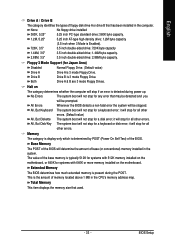
... the amount of base (or conventional) memory installed in the system. Total Memory This item displays the memory size that has been installed in the CPU's memory address map. The system boot will not stop for any error that may be detected and you will not stop for a disk error; Both...
... the amount of base (or conventional) memory installed in the system. Total Memory This item displays the memory size that has been installed in the CPU's memory address map. The system boot will not stop for any error that may be detected and you will not stop for a disk error; Both...
Manual
Page 34
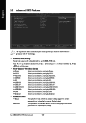
...not access to Setup page if the correct password is not entered at the prompt. LAN Select your boot device priority by USB-ZIP. GA-8I865GM(F)K-775 Motherboard - 34 - Hard Disk Boot Priority Select boot sequence for onboard(or add-on cards) SCSI, RAID, etc. USB-FDD Select...Copyright (C) 1984-2005 Award Software Advanced BIOS Features ` Hard Disk Boot Priority First Boot Device Second Boot Device Third Boot Device Password Check # CPU Hyper-Threading Limit CPUID Max. Hard Disk Select your boot device priority by ZIP. to exit this menu. First / Second / Third Boot ...
...not access to Setup page if the correct password is not entered at the prompt. LAN Select your boot device priority by USB-ZIP. GA-8I865GM(F)K-775 Motherboard - 34 - Hard Disk Boot Priority Select boot sequence for onboard(or add-on cards) SCSI, RAID, etc. USB-FDD Select...Copyright (C) 1984-2005 Award Software Advanced BIOS Features ` Hard Disk Boot Priority First Boot Device Second Boot Device Third Boot Device Password Check # CPU Hyper-Threading Limit CPUID Max. Hard Disk Select your boot device priority by ZIP. to exit this menu. First / Second / Third Boot ...
Manual
Page 35
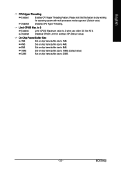
...-chip frame buffer size to 8MB. BIOS Setup to 3 Enabled Disabled Limit CPUID Maximum value to 32MB. - 35 - English CPU Hyper-Threading Enabled Disabled Enables CPU Hyper Threading Feature. Limit CPUID Max. Please note that this feature is only working for windows XP.(Default value) On-Chip Frame...16MB Set on -chip frame buffer size to 4MB. Disables CPUID Limit for operating system with multi processors mode supported. (Default value) Disables CPU Hyper Threading. Set on-chip frame buffer size to 16MB. (Default value) 32MB Set on-chip frame buffer size to 3 when use ...
...-chip frame buffer size to 8MB. BIOS Setup to 3 Enabled Disabled Limit CPUID Maximum value to 32MB. - 35 - English CPU Hyper-Threading Enabled Disabled Enables CPU Hyper Threading Feature. Limit CPUID Max. Please note that this feature is only working for windows XP.(Default value) On-Chip Frame...16MB Set on -chip frame buffer size to 4MB. Disables CPUID Limit for operating system with multi processors mode supported. (Default value) Disables CPU Hyper Threading. Set on-chip frame buffer size to 16MB. (Default value) 32MB Set on-chip frame buffer size to 3 when use ...

Manual
Page 41
.... When this function. Note: In fact, the Voltage option can adjust the fan speed with 3-pin or 4-pin power cables. However, some 4-pin CPU fan power cables are not designed following Intel 4-Wire fans PWM control specifications. Current Voltage(V) Vcore / +3.3V / +5V / +12V / DDR25V Detect... system's voltage status automatically. Auto Voltage BIOS autodetects the type of CPU fan you use a CPU fan with a 4-pin fan power cable. Users can be used for it. (Default Value) Set to PWM when you installed and sets ...
.... When this function. Note: In fact, the Voltage option can adjust the fan speed with 3-pin or 4-pin power cables. However, some 4-pin CPU fan power cables are not designed following Intel 4-Wire fans PWM control specifications. Current Voltage(V) Vcore / +3.3V / +5V / +12V / DDR25V Detect... system's voltage status automatically. Auto Voltage BIOS autodetects the type of CPU fan you use a CPU fan with a 4-pin fan power cable. Users can be used for it. (Default Value) Set to PWM when you installed and sets ...
Manual
Page 42
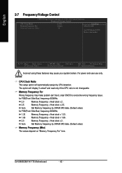
...Control CMOS Setup Utility-Copyright (C) 1984-2005 Award Software Frequency/Voltage Control CPU Clock Ratio Memory Frequency For Memory Frequency (Mhz) [15X] [Auto] 266 Item Help Menu Level` Set CPU Ratio if CPU Ratio is not changeable. Auto Set Memory frequency by DRAM SPD data.... (Mhz) The values depend on "Memory Frequency For" item. GA-8I865GM(F)K-775 Motherboard - 42 - Auto Set Memory frequency by CPU detection. CPU Clock Ratio This setup option will display "Locked" and read only if the CPU ratio is unclocked KLJI: Move Enter: Select F5: Previous Values ...
...Control CMOS Setup Utility-Copyright (C) 1984-2005 Award Software Frequency/Voltage Control CPU Clock Ratio Memory Frequency For Memory Frequency (Mhz) [15X] [Auto] 266 Item Help Menu Level` Set CPU Ratio if CPU Ratio is not changeable. Auto Set Memory frequency by DRAM SPD data.... (Mhz) The values depend on "Memory Frequency For" item. GA-8I865GM(F)K-775 Motherboard - 42 - Auto Set Memory frequency by CPU detection. CPU Clock Ratio This setup option will display "Locked" and read only if the CPU ratio is unclocked KLJI: Move Enter: Select F5: Previous Values ...
Manual
Page 51
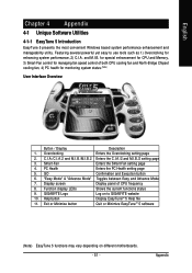
...setting page 5. "Easy Mode" & "Advance Mode" Toggles between Easy and Advance Mode 7. Display screen Display panel of both CPU cooling fan and North-Bridge Chipset cooling fan, 4) PC health for enhancing system performance, 2) C.I.A. Appendix Overclocking Enters the ...for monitoring system status.(Note) User Interface Overview Button / Display Description 1. Smart-Fan Enters the Smart-Fan setting page 4. GIGABYTE Logo Log on different motherboards. - 51 - English Chapter 4 Appendix 4-1 Unique Software Utilities 4-1-1 EasyTune 5 Introduction EasyTune 5...
...setting page 5. "Easy Mode" & "Advance Mode" Toggles between Easy and Advance Mode 7. Display screen Display panel of both CPU cooling fan and North-Bridge Chipset cooling fan, 4) PC health for enhancing system performance, 2) C.I.A. Appendix Overclocking Enters the ...for monitoring system status.(Note) User Interface Overview Button / Display Description 1. Smart-Fan Enters the Smart-Fan setting page 4. GIGABYTE Logo Log on different motherboards. - 51 - English Chapter 4 Appendix 4-1 Unique Software Utilities 4-1-1 EasyTune 5 Introduction EasyTune 5...


