User Manual
Page 1
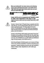
... switching the jumper to boot up normally. The GA-8I848P(-G) (or any AGP 4X/8X only) motherboards might not function properly, If you install this card is compliance with Intel® 845(GE/PE) / 845(E/G) / 850(E) / E7205 / 865(G/PE/PL/P) / 875P / 848P based motherboards. Note: Although Gigabyte's AG32S(G) graphics card is based on ATi Rage...
... switching the jumper to boot up normally. The GA-8I848P(-G) (or any AGP 4X/8X only) motherboards might not function properly, If you install this card is compliance with Intel® 845(GE/PE) / 845(E/G) / 850(E) / E7205 / 865(G/PE/PL/P) / 875P / 848P based motherboards. Note: Although Gigabyte's AG32S(G) graphics card is based on ATi Rage...

User Manual
Page 2
0 The author assumes no responsibility for any errors or omissions that may appear in this document nor does the author make a commitment to update the information contained herein. 0 Third-party brands and names are the property of their respective owners. 0 Please do not remove any labels on motherboard, this may void the warranty of this motherboard. 0 Due to rapid change in technology, some of the specifications might be out of date before publication of this booklet.
0 The author assumes no responsibility for any errors or omissions that may appear in this document nor does the author make a commitment to update the information contained herein. 0 Third-party brands and names are the property of their respective owners. 0 Please do not remove any labels on motherboard, this may void the warranty of this motherboard. 0 Due to rapid change in technology, some of the specifications might be out of date before publication of this booklet.

User Manual
Page 4
... the following two conditions: (1) This device may not cause harmful and (2) this device must accept any inference received, including that the product Product Name: Motherboard Model Number: GA-8I848P-G/GA-8I848P Conforms to the following specifications: FCC Part 15, Subpart B, Section 15.107(a) and Section 15.109 (a),Class B Digital Device Supplementary Information: This device complies...
... the following two conditions: (1) This device may not cause harmful and (2) this device must accept any inference received, including that the product Product Name: Motherboard Model Number: GA-8I848P-G/GA-8I848P Conforms to the following specifications: FCC Part 15, Subpart B, Section 15.107(a) and Section 15.109 (a),Class B Digital Device Supplementary Information: This device complies...

User Manual
Page 5
GA-8I848P(-G) P4 Titan Series Motherboard USER'S MANUAL Pentium®4 Processor Motherboard Rev. 2002 12ME-8I848P-2002
GA-8I848P(-G) P4 Titan Series Motherboard USER'S MANUAL Pentium®4 Processor Motherboard Rev. 2002 12ME-8I848P-2002

User Manual
Page 6
English Table of Content Item Checklist 4 Chapter 1 Introduction 5 Features Summary 5 GA-8I848P(-G) Motherboard Layout 7 Block Diagram 8 Chapter 2 Hardware Installation Process 10 Step 1: Install the Central Processing Unit (CPU 11 Step 1-1: CPU Installation 11 Step 1-2 : CPU Cooling Fan Installation ... 31 The Main Menu (For example: BIOS Ver. : E1 32 Standard CMOS Features 34 Advanced BIOS Features 37 Integrated Peripherals 39 Power Management Setup 44 GA-8I848P(-G) Motherboard - 2 -
English Table of Content Item Checklist 4 Chapter 1 Introduction 5 Features Summary 5 GA-8I848P(-G) Motherboard Layout 7 Block Diagram 8 Chapter 2 Hardware Installation Process 10 Step 1: Install the Central Processing Unit (CPU 11 Step 1-1: CPU Installation 11 Step 1-2 : CPU Cooling Fan Installation ... 31 The Main Menu (For example: BIOS Ver. : E1 32 Standard CMOS Features 34 Advanced BIOS Features 37 Integrated Peripherals 39 Power Management Setup 44 GA-8I848P(-G) Motherboard - 2 -

User Manual
Page 8
... your computer when working on your hands to a safely grounded object or to the chassis... English Item Checklist The GA-8I848P or GA-8I848P-G motherboard IDE cable x 2 / Floppy cable x 1 CD for motherboard driver & utility GA-8I848P(-G) user's manual I/O Shield Quick PC Installation Guide RAID Manual GC-SATA Card (Optional) (Manual; Power cable x 1) 2 Port USB Cable x 1 4 Port USB Cable...
... your computer when working on your hands to a safely grounded object or to the chassis... English Item Checklist The GA-8I848P or GA-8I848P-G motherboard IDE cable x 2 / Floppy cable x 1 CD for motherboard driver & utility GA-8I848P(-G) user's manual I/O Shield Quick PC Installation Guide RAID Manual GC-SATA Card (Optional) (Manual; Power cable x 1) 2 Port USB Cable x 1 4 Port USB Cable...
User Manual
Page 10
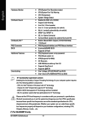
GA-8I848P(-G) Motherboard - 6 - We don't recommend you to set the CPU host frequency in Marvell 8001 Chipset (10/100/1000 Mbit) y 1 RJ45 port y PS/2 Keyboard interface and PS/2 ... Surround-Kit) y Build in accordance with HT Technology - CPU: An Intel® Pentium 4 Processor with your hardware configurations, including CPU, Chipsets, Memory, Cards....etc. (*) For GA-8I848P-G only.
GA-8I848P(-G) Motherboard - 6 - We don't recommend you to set the CPU host frequency in Marvell 8001 Chipset (10/100/1000 Mbit) y 1 RJ45 port y PS/2 Keyboard interface and PS/2 ... Surround-Kit) y Build in accordance with HT Technology - CPU: An Intel® Pentium 4 Processor with your hardware configurations, including CPU, Chipsets, Memory, Cards....etc. (*) For GA-8I848P-G only.
User Manual
Page 11
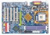
Introduction English GA-8I848P(-G) Motherboard Layout KB_MS USB COMA ATX_12V SOCKET478 CPU_FAN ATX FDD COMB LPT GA-8I848P-G Hyper Threading DDR1 DDR2 DDR3 MIC_IN USB LINE_OUT LINE_IN LAN (*) F_AUDIO CD_IN Intel® 848P Marvell 8001 (*) AGP 8X AGP BAT CLR_CMOS CODEC SUR_CEN ITE8712 GAME ICH5 PCI1 SATA PCI2 P4 Titan BIOS PCI3 SATA0 SATA1 CI IR SPDIF_IO PCI4 PCI5 INFO_LINK F_USB2 F_USB1 IDE2 IDE1 SYS_FAN F_PANEL PWR_LED (*) For GA-8I848P-G only. - 7 -
Introduction English GA-8I848P(-G) Motherboard Layout KB_MS USB COMA ATX_12V SOCKET478 CPU_FAN ATX FDD COMB LPT GA-8I848P-G Hyper Threading DDR1 DDR2 DDR3 MIC_IN USB LINE_OUT LINE_IN LAN (*) F_AUDIO CD_IN Intel® 848P Marvell 8001 (*) AGP 8X AGP BAT CLR_CMOS CODEC SUR_CEN ITE8712 GAME ICH5 PCI1 SATA PCI2 P4 Titan BIOS PCI3 SATA0 SATA1 CI IR SPDIF_IO PCI4 PCI5 INFO_LINK F_USB2 F_USB1 IDE2 IDE1 SYS_FAN F_PANEL PWR_LED (*) For GA-8I848P-G only. - 7 -

User Manual
Page 12
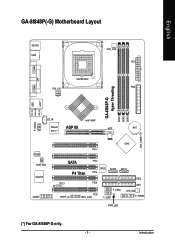
ZCLK (66MHz) CPUCLK+/- (100/133/200MHz) AGPCLK (66MHz) HCLK+/- (100/133/200MHz) ICH3V66 (66MHz) GA-8I848P(-G) Motherboard CLK GEN - 8 - English Block Diagram AGP 8X/4X AGPCLK (66MHz) 5 PCI RJ45 (*) Marvell 8001 (*) Pentium 4 Socket 478 CPU CPUCLK+/- (100/133/200MHz) System Bus 400/.../100 IDE Channels 33 MHz Serial ATA Channels PS/2 KB/Mouse COM Ports PCICLK (33MHz) USBCLK (48MHz) 14.318 MHz 33 MHz 24 MHz (*) For GA-8I848P-G only.
ZCLK (66MHz) CPUCLK+/- (100/133/200MHz) AGPCLK (66MHz) HCLK+/- (100/133/200MHz) ICH3V66 (66MHz) GA-8I848P(-G) Motherboard CLK GEN - 8 - English Block Diagram AGP 8X/4X AGPCLK (66MHz) 5 PCI RJ45 (*) Marvell 8001 (*) Pentium 4 Socket 478 CPU CPUCLK+/- (100/133/200MHz) System Bus 400/.../100 IDE Channels 33 MHz Serial ATA Channels PS/2 KB/Mouse COM Ports PCICLK (33MHz) USBCLK (48MHz) 14.318 MHz 33 MHz 24 MHz (*) For GA-8I848P-G only.
User Manual
Page 14
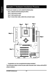
English Chapter 2 Hardware Installation Process To set up your computer, you have accomplished the hardware installation! GA-8I848P(-G) Motherboard - 10 - Install expansion cards Step 4- Install memory modules Step 3- Turn on the power supply or connect the power cable to the power outlet. Connect ribbon cables, cabinet wires, and power supply Step 4 Step 1 Step 2 Step 4 Step 4 Step 3 Congratulations you must complete the following steps: Step 1- Install the Central Processing Unit (CPU) Step 2- Continue with the BIOS/ software installation.
English Chapter 2 Hardware Installation Process To set up your computer, you have accomplished the hardware installation! GA-8I848P(-G) Motherboard - 10 - Install expansion cards Step 4- Install memory modules Step 3- Turn on the power supply or connect the power cable to the power outlet. Connect ribbon cables, cabinet wires, and power supply Step 4 Step 1 Step 2 Step 4 Step 4 Step 3 Congratulations you must complete the following steps: Step 1- Install the Central Processing Unit (CPU) Step 2- Continue with the BIOS/ software installation.

User Manual
Page 15
Please make sure the CPU type is supported by the motherboard. Step 1-1: CPU Installation Angling the rod to the 90-degree directly. Then insert the CPU into the socket. - 11 - Hardware Installation Process Pull the rod ...
Please make sure the CPU type is supported by the motherboard. Step 1-1: CPU Installation Angling the rod to the 90-degree directly. Then insert the CPU into the socket. - 11 - Hardware Installation Process Pull the rod ...

User Manual
Page 16
... thermal paste, or remove the cooling fan with the cooling fan, and might stick to the CPU due to either use Intel approved cooling fan. 2. GA-8I848P(-G) Motherboard - 12 - Please use thermal tape instead of the thermal paste. Fasten the cooling fan supporting-base onto the CPU socket on the mainboard. 2. English Step...
... thermal paste, or remove the cooling fan with the cooling fan, and might stick to the CPU due to either use Intel approved cooling fan. 2. GA-8I848P(-G) Motherboard - 12 - Please use thermal tape instead of the thermal paste. Fasten the cooling fan supporting-base onto the CPU socket on the mainboard. 2. English Step...

User Manual
Page 17
... automatically detects memory type and size. Please change the insert orientation. To install the memory module, just push it vertically into the DIMM socket. The motherboard has 3 dual inline memory module (DIMM) sockets. The DIMM module can only fit in one direction due to the one direction due to the notch...
... automatically detects memory type and size. Please change the insert orientation. To install the memory module, just push it vertically into the DIMM socket. The motherboard has 3 dual inline memory module (DIMM) sockets. The DIMM module can only fit in one direction due to the one direction due to the notch...

User Manual
Page 18
... slot. DDR memory is a high performance and cost-effective solution that builds on the existing SDRAM architecture, yet make the awesome advances in one direction. 2. GA-8I848P(-G) Motherboard - 14 - The DIMM slot has a notch, so the DIMM memory module can only fit in solving the system performance bottleneck by doubling the memory bandwidth...
... slot. DDR memory is a high performance and cost-effective solution that builds on the existing SDRAM architecture, yet make the awesome advances in one direction. 2. GA-8I848P(-G) Motherboard - 14 - The DIMM slot has a notch, so the DIMM memory module can only fit in solving the system performance bottleneck by doubling the memory bandwidth...

User Manual
Page 19
English Step 3: Install expansion cards 1. Be sure the metal contacts on the card are indeed seated in motherboard. 4. Power on the slot .Make sure your AGP card is locked by the small whitedrawable bar. - 15 - Install related driver from the computer. 3. drawable bar ...
English Step 3: Install expansion cards 1. Be sure the metal contacts on the card are indeed seated in motherboard. 4. Power on the slot .Make sure your AGP card is locked by the small whitedrawable bar. - 15 - Install related driver from the computer. 3. drawable bar ...

User Manual
Page 20
... your device(s) into USB connector(s), please make sure your OS or device(s) vendors. If your device(s) such as USB keyboard,mouse, scanner, zip, speaker..etc. GA-8I848P(-G) Motherboard - 16 - English Step 4: Connect ribbon cables, cabinet wires, and power supply Step 4-1: I/O Back Panel Introduction X Z Y \ [ X PS/2 Keyboard and PS/2 Mouse Connector PS/2 Mouse Connector (6 pin...
... your device(s) into USB connector(s), please make sure your OS or device(s) vendors. If your device(s) such as USB keyboard,mouse, scanner, zip, speaker..etc. GA-8I848P(-G) Motherboard - 16 - English Step 4: Connect ribbon cables, cabinet wires, and power supply Step 4-1: I/O Back Panel Introduction X Z Y \ [ X PS/2 Keyboard and PS/2 Mouse Connector PS/2 Mouse Connector (6 pin...

User Manual
Page 22
English Step 4-2: Connectors & Jumper Setting Introduction 1 3 2 6 12 10 8 20 11 18 19 5 14 4 16 13 17 15 7 9 1) ATX_12V 2) ATX 3) CPU_FAN 4) SYS_FAN 5) IDE1/IDE2 6) FDD 7) PWR_LED 8) BAT 9) F_PANEL 10) F_AUDIO 11) SUR_CEN 12) CD_IN 13) SPDIF_IO 14) IR 15) F_USB1/F_USB2 16) GAME 17) INFO_LINK 18) SATA0/SATA1 19) CI 20) CLR_CMOS GA-8I848P(-G) Motherboard - 18 -
English Step 4-2: Connectors & Jumper Setting Introduction 1 3 2 6 12 10 8 20 11 18 19 5 14 4 16 13 17 15 7 9 1) ATX_12V 2) ATX 3) CPU_FAN 4) SYS_FAN 5) IDE1/IDE2 6) FDD 7) PWR_LED 8) BAT 9) F_PANEL 10) F_AUDIO 11) SUR_CEN 12) CD_IN 13) SPDIF_IO 14) IR 15) F_USB1/F_USB2 16) GAME 17) INFO_LINK 18) SATA0/SATA1 19) CI 20) CLR_CMOS GA-8I848P(-G) Motherboard - 18 -

User Manual
Page 24
Definition 1 GND 1 2 +12V 3 Sense GA-8I848P(-G) Motherboard - 20 - Pin No. English 3) CPU_FAN (CPU FAN Connector) Please note, a proper installation of the CPU cooler is essential to 600 mA. Pin No. current up to prevent the CPU from running under abnormal condition or damaged by overheating.The CPU fan connector supports Max. Definition 1 1 GND 2 +12V 3 Sense 4) SYS_FAN (System FAN Connector) This connector allows you to link with the cooling fan on the system case to lower the system temperature.
Definition 1 GND 1 2 +12V 3 Sense GA-8I848P(-G) Motherboard - 20 - Pin No. English 3) CPU_FAN (CPU FAN Connector) Please note, a proper installation of the CPU cooler is essential to 600 mA. Pin No. current up to prevent the CPU from running under abnormal condition or damaged by overheating.The CPU fan connector supports Max. Definition 1 1 GND 2 +12V 3 Sense 4) SYS_FAN (System FAN Connector) This connector allows you to link with the cooling fan on the system case to lower the system temperature.

User Manual
Page 26
... power cord. 2.Remove the battery, wait for 30 second. 3.Re-install the battery. 4.Plug the power cord and turn to the manufacturer's instructions. Pin No. GA-8I848P(-G) Motherboard - 22 - English 7) PWR_LED PWR_LED is on/off. It will turn ON the computer.
... power cord. 2.Remove the battery, wait for 30 second. 3.Re-install the battery. 4.Plug the power cord and turn to the manufacturer's instructions. Pin No. GA-8I848P(-G) Motherboard - 22 - English 7) PWR_LED PWR_LED is on/off. It will turn ON the computer.

User Manual
Page 28
... audio header, your nearest dealer for optional SUR_CEN cable. 12 78 Pin No. 1 2 3 4 5 6 7 8 Definition SUR OUTL SUR OUTR GND No Pin CENTER_OUT BASS_OUT AUX_L AUX_R GA-8I848P(-G) Motherboard - 24 - Also please make sure the pin assigment on the cable is the same as the pin assigment on the MB header.
... audio header, your nearest dealer for optional SUR_CEN cable. 12 78 Pin No. 1 2 3 4 5 6 7 8 Definition SUR OUTL SUR OUTR GND No Pin CENTER_OUT BASS_OUT AUX_L AUX_R GA-8I848P(-G) Motherboard - 24 - Also please make sure the pin assigment on the cable is the same as the pin assigment on the MB header.


