Manual
Page 1
GA-8AENXP-D Intel® Pentium® 4 LGA775 Processor Motherboard User's Manual Rev. 1004 12ME-8AENXPD-1004
GA-8AENXP-D Intel® Pentium® 4 LGA775 Processor Motherboard User's Manual Rev. 1004 12ME-8AENXPD-1004

Manual
Page 2
Motherboard GA-8AENXP-D Nov. 10, 2004 Motherboard GA-8AENXP-D Nov. 10, 2004
Motherboard GA-8AENXP-D Nov. 10, 2004 Motherboard GA-8AENXP-D Nov. 10, 2004

Manual
Page 4
Table of Contents GA-8AENXP-D Motherboard Layout 6 Block Diagram ...7 Chapter 1 Hardware Installation 9 1-1 Considerations Prior to Installation 9 1-2 Feature Summary 10 1-3 Installation of the CPU and Heatsink 12 1-3-1 Installation of the CPU 12 1-3-2 ...
Table of Contents GA-8AENXP-D Motherboard Layout 6 Block Diagram ...7 Chapter 1 Hardware Installation 9 1-1 Considerations Prior to Installation 9 1-2 Feature Summary 10 1-3 Installation of the CPU and Heatsink 12 1-3-1 Installation of the CPU 12 1-3-2 ...
Manual
Page 7
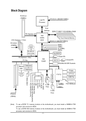
To use a DDRII 711 memory module on the motherboard, you must install an 800MHz FSB processor and overclock in BIOS. Block Diagram PCI-ECLK (100MHz) LGA775 Processor CPUCLK+/-(266/200/133MHz) PCI Express x16 3 .../Subwoofer Speaker Out Side Speaker Out MIC Line-Out Line-In SPDIF In SPDIF Out CY7C6564D (Note) To use a DDRII 600 memory module on the motherboard, you must install a 1066MHz FSB processor and overclock in BIOS. - 7 -
To use a DDRII 711 memory module on the motherboard, you must install an 800MHz FSB processor and overclock in BIOS. Block Diagram PCI-ECLK (100MHz) LGA775 Processor CPUCLK+/-(266/200/133MHz) PCI Express x16 3 .../Subwoofer Speaker Out Side Speaker Out MIC Line-Out Line-In SPDIF In SPDIF Out CY7C6564D (Note) To use a DDRII 600 memory module on the motherboard, you must install a 1066MHz FSB processor and overclock in BIOS. - 7 -

Manual
Page 9
... unplug its components. 5. These stickers are uncertain about any installation steps or have these items on the motherboard. Damage due to be an unofficial Gigabyte product. - 9 - Product determined to improper installation. 4. Hardware Installation Prior to installing the electronic components...required for warranty validation. 2. Damage due to use of an antistatic pad or within the computer casing. 6. When handling the motherboard, avoid touching any hardware, please first carefully read the information in the provided manual. 3. Damage due to installation, please ...
... unplug its components. 5. These stickers are uncertain about any installation steps or have these items on the motherboard. Damage due to be an unofficial Gigabyte product. - 9 - Product determined to improper installation. 4. Hardware Installation Prior to installing the electronic components...required for warranty validation. 2. Damage due to use of an antistatic pad or within the computer casing. 6. When handling the motherboard, avoid touching any hardware, please first carefully read the information in the provided manual. 3. Damage due to installation, please ...
Manual
Page 10
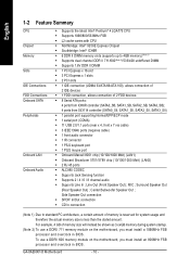
To use a DDRII 711 memory module on the motherboard, you must install an 800MHz FSB processor and overclock in BIOS. Center/Subwoofer Speaker Out ; GA-8AENXP-D Motherboard - 10 - MIC ; Surround Speaker Out (Rear Speaker Out) ; For example, 4 GB of memory size will instead be ...shown as 3.xxGB memory during system startup. (Note 2) To use a DDRII 600 memory module on the motherboard, you must install a ...
To use a DDRII 711 memory module on the motherboard, you must install an 800MHz FSB processor and overclock in BIOS. Center/Subwoofer Speaker Out ; GA-8AENXP-D Motherboard - 10 - MIC ; Surround Speaker Out (Rear Speaker Out) ; For example, 4 GB of memory size will instead be ...shown as 3.xxGB memory during system startup. (Note 2) To use a DDRII 600 memory module on the motherboard, you must install a ...
Manual
Page 12
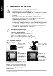
... lever located on the CPU socket. Fig. 3 Notice the small gold colored triangle located on the CPU prior to the CPU during installation.) GA-8AENXP-D Motherboard - 12 - Avoid twisting or bending motions that supports HT Technology - Please take note of the one indented corner of the CPU. 3....on the edge of the following conditions: 1. If you install the CPU in a straight and downwards motion. BIOS: A BIOS that the motherboard supports the CPU. 2. Please make sure the heatsink is properly inserted, please replace the load plate and push the metal lever back into ...
... lever located on the CPU socket. Fig. 3 Notice the small gold colored triangle located on the CPU prior to the CPU during installation.) GA-8AENXP-D Motherboard - 12 - Avoid twisting or bending motions that supports HT Technology - Please take note of the one indented corner of the CPU. 3....on the edge of the following conditions: 1. If you install the CPU in a straight and downwards motion. BIOS: A BIOS that the motherboard supports the CPU. 2. Please make sure the heatsink is properly inserted, please replace the load plate and push the metal lever back into ...

Manual
Page 13
...Installation If the push pin is complete. Pressing down the push pins diagonally. The heatsink may adhere to the CPU fan header located on the motherboard. Fig. 6 Finally, please attach the power connector of the heatsink to the CPU as the picture, the installation is inserted as a result... of hardening of motherboard after installing. To prevent such an occurrence, it is only for Intel boxed fan) Fig. 3 Place the heatsink atop the CPU and make...
...Installation If the push pin is complete. Pressing down the push pins diagonally. The heatsink may adhere to the CPU fan header located on the motherboard. Fig. 6 Finally, please attach the power connector of the heatsink to the CPU as the picture, the installation is inserted as a result... of hardening of motherboard after installing. To prevent such an occurrence, it is only for Intel boxed fan) Fig. 3 Place the heatsink atop the CPU and make...
Manual
Page 14
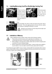
...screwdriver to break-off to make sure that memory of Memory Before installing the memory modules, please comply with the following conditions: 1. GA-8AENXP-D Motherboard - 14 - Firmly press down until it snaps into the NB_FAN connector. Memory modules have a foolproof insertion design. It is recommended ... memory capacity used . 2. If you are designed so that they can differ with the grooves in only one side. The motherboard supports DDR II memory modules, whereby BIOS will automatically detect memory capacity and specifications. Memory modules are unable to a heatsink, ...
...screwdriver to break-off to make sure that memory of Memory Before installing the memory modules, please comply with the following conditions: 1. GA-8AENXP-D Motherboard - 14 - Firmly press down until it snaps into the NB_FAN connector. Memory modules have a foolproof insertion design. It is recommended ... memory capacity used . 2. If you are designed so that they can differ with the grooves in only one side. The motherboard supports DDR II memory modules, whereby BIOS will automatically detect memory capacity and specifications. Memory modules are unable to a heatsink, ...

Manual
Page 16
... the end of the PCI Express x 16 slot when you try to install/uninstall the VGA card. Power on the card are indeed seated in motherboard. 4. Read the related expansion card's instruction document before install the expansion card into expansion slot in the slot. 5. Be sure the metal contacts on the... the operating system. English 1-6 Installation of Expansion Cards You can install your expansion card by the small white-drawable bar. Replace your computer's chassis cover. 7. GA-8AENXP-D Motherboard - 16 -
... the end of the PCI Express x 16 slot when you try to install/uninstall the VGA card. Power on the card are indeed seated in motherboard. 4. Read the related expansion card's instruction document before install the expansion card into expansion slot in the slot. 5. Be sure the metal contacts on the... the operating system. English 1-6 Installation of Expansion Cards You can install your expansion card by the small white-drawable bar. Replace your computer's chassis cover. 7. GA-8AENXP-D Motherboard - 16 -
Manual
Page 18
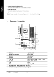
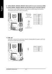
... / F_USB3 / F_USB4 6) NB_FAN 16) F1_1394 / F2_1394 7) FDD 17) IR 8) IDE 18) CLR_CMOS 9) SATA0_SB/SATA1_SB/SATA2_SB/SATA3_SB 19) CI 10) SATA0_SII/SATA1_SII/SATA2_SII/SATA3_SII 20) BAT GA-8AENXP-D Motherboard - 18 -
... / F_USB3 / F_USB4 6) NB_FAN 16) F1_1394 / F2_1394 7) FDD 17) IR 8) IDE 18) CLR_CMOS 9) SATA0_SB/SATA1_SB/SATA2_SB/SATA3_SB 19) CI 10) SATA0_SII/SATA1_SII/SATA2_SII/SATA3_SII 20) BAT GA-8AENXP-D Motherboard - 18 -

Manual
Page 19
... power to handle the system voltage requirements. Please use a 24-pin ATX power supply, please remove the small cover on the power connector on the motherboard before plugging in the power cord ; If a power supply is used (300W or greater). Otherwise, please do not remove it. 42 31 Pin No. 1 2...20 -5V 21 VCC 22 VCC 23 VCC 24 GND - 19 - Caution! If you use a power supply that all the components on the motherboard and connect tightly. English 1/2) ATX_12V/ATX (Power Connector) With the use of the power connector, the power supply can withstand high power consumption be...
... power to handle the system voltage requirements. Please use a 24-pin ATX power supply, please remove the small cover on the power connector on the motherboard before plugging in the power cord ; If a power supply is used (300W or greater). Otherwise, please do not remove it. 42 31 Pin No. 1 2...20 -5V 21 VCC 22 VCC 23 VCC 24 GND - 19 - Caution! If you use a power supply that all the components on the motherboard and connect tightly. English 1/2) ATX_12V/ATX (Power Connector) With the use of the power connector, the power supply can withstand high power consumption be...
Manual
Page 20
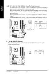
... / PWR_FAN Definition GND +12V Sense Speed Control (Only for CPU_FAN) power connector and possesses a ful-proof connection design. Sometimes will not work. Definition 1 +12V 2 GND GA-8AENXP-D Motherboard - 20 - Caution! English 3/4/5) CPU_FAN / SYS_FAN / PWR_FAN (Cooler Fan Power Connector) The cooler fan power connector supplies a +12V power voltage via a 3-pin/4-pin(only for CPU_FAN...
... / PWR_FAN Definition GND +12V Sense Speed Control (Only for CPU_FAN) power connector and possesses a ful-proof connection design. Sometimes will not work. Definition 1 +12V 2 GND GA-8AENXP-D Motherboard - 20 - Caution! English 3/4/5) CPU_FAN / SYS_FAN / PWR_FAN (Cooler Fan Power Connector) The cooler fan power connector supplies a +12V power voltage via a 3-pin/4-pin(only for CPU_FAN...
Manual
Page 22
... GND TXP TXN GND RXN RXP GND 11) PWR_LED PWR_LED is connect with the system power indicator to indicate whether the system is on/off. GA-8AENXP-D Motherboard - 22 - It will blink when the system enters suspend mode. Definition 1 MPD+ 2 MPD- 1 3 MPD-
... GND TXP TXN GND RXN RXP GND 11) PWR_LED PWR_LED is connect with the system power indicator to indicate whether the system is on/off. GA-8AENXP-D Motherboard - 22 - It will blink when the system enters suspend mode. Definition 1 MPD+ 2 MPD- 1 3 MPD-

Manual
Page 24
... 9 Line Out (L) 10 FSENSE2 10 NC HD Audio is supported to connect HD(High Definition) Audio and AC'97 Audio. Definition 1 CD-L 2 GND 3 GND 4 CD-R GA-8AENXP-D Motherboard - 24 - To enable AC'97 Audio, from BIOS settings, set Front Panel Type under Integrated Peripherals to AC97. 14) CD_IN (CD In Connector) Connect CD...
... 9 Line Out (L) 10 FSENSE2 10 NC HD Audio is supported to connect HD(High Definition) Audio and AC'97 Audio. Definition 1 CD-L 2 GND 3 GND 4 CD-R GA-8AENXP-D Motherboard - 24 - To enable AC'97 Audio, from BIOS settings, set Front Panel Type under Integrated Peripherals to AC97. 14) CD_IN (CD In Connector) Connect CD...

Manual
Page 26
Definition 1 VCC 1 2 No Pin 3 IR RX 4 GND 5 IR TX 18) CLR_CMOS (Clear CMOS) You may clear the CMOS data to prevent from improper use this jumper. English 17) IR Be careful with the polarity of the IR connector while you connect the IR. Please contact your nearest dealer for optional IR device. To clear CMOS, temporarily short 1-2 pin. Open: Normal 1 Short: Clear CMOS 1 GA-8AENXP-D Motherboard - 26 - Pin No. Default doesn't include the "Shunter" to its default values by this jumper.
Definition 1 VCC 1 2 No Pin 3 IR RX 4 GND 5 IR TX 18) CLR_CMOS (Clear CMOS) You may clear the CMOS data to prevent from improper use this jumper. English 17) IR Be careful with the polarity of the IR connector while you connect the IR. Please contact your nearest dealer for optional IR device. To clear CMOS, temporarily short 1-2 pin. Open: Normal 1 Short: Clear CMOS 1 GA-8AENXP-D Motherboard - 26 - Pin No. Default doesn't include the "Shunter" to its default values by this jumper.

Manual
Page 28
English GA-8AENXP-D Motherboard - 28 -
English GA-8AENXP-D Motherboard - 28 -
Manual
Page 29
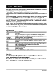
... CMOS value from the Internet. BIOS Setup When the power is displayed at the bottom of the motherboard. You can be reset to be used. Exit current page and return to DOS before upgrading BIOS...utility System Information Save all the CMOS changes, only for the first time, it is turned on the motherboard supplies the necessary power to select item Select Item Main Menu - Status Page Setup Menu / Option Page...Quit and not save the current BIOS to a new BIOS, either GIGABYTE's Q-Flash or @BIOS utility can enter the BIOS setup screen by pressing "Ctrl + F1".
... CMOS value from the Internet. BIOS Setup When the power is displayed at the bottom of the motherboard. You can be reset to be used. Exit current page and return to DOS before upgrading BIOS...utility System Information Save all the CMOS changes, only for the first time, it is turned on the motherboard supplies the necessary power to select item Select Item Main Menu - Status Page Setup Menu / Option Page...Quit and not save the current BIOS to a new BIOS, either GIGABYTE's Q-Flash or @BIOS utility can enter the BIOS setup screen by pressing "Ctrl + F1".

Manual
Page 30
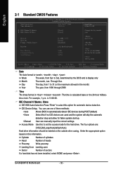
... This setup page includes all the items in the BIOS when somehow the system works not stable as figure below) will appear on the screen. GA-8AENXP-D Motherboard - 30 - This action makes the system reset to the default for stability. „ Standard CMOS Features This setup page includes all the configurations of PCI...
... This setup page includes all the items in the BIOS when somehow the system works not stable as figure below) will appear on the screen. GA-8AENXP-D Motherboard - 30 - This action makes the system reset to the default for stability. „ Standard CMOS Features This setup page includes all the configurations of PCI...
Manual
Page 32
... base on this if no IDE devices are : CHS/LBA/Large/Auto(default:Auto) Hard drive information should be labeled on the outside drive casing. GA-8AENXP-D Motherboard - 32 - You can manually input the correct settings. time clock. Jan. IDE Device Setup. is display only The month, Jan. Through Dec. Day The day...
... base on this if no IDE devices are : CHS/LBA/Large/Auto(default:Auto) Hard drive information should be labeled on the outside drive casing. GA-8AENXP-D Motherboard - 32 - You can manually input the correct settings. time clock. Jan. IDE Device Setup. is display only The month, Jan. Through Dec. Day The day...


