Manual
Page 3
...respective owners. For product-related information, check on our website at: http://www.gigabyte.com.tw Identifying Your Motherboard Revision The revision number on your motherboard revision before updating motherboard BIOS, drivers, or when looking for technical information. Example: Changes to use of the... the following types of documentations: For quick set-up of this manual may be made by any form or by GIGABYTE without GIGABYTE's prior written permission. All rights reserved. For detailed product information, carefully read the Quick Installation Guide included with the...
...respective owners. For product-related information, check on our website at: http://www.gigabyte.com.tw Identifying Your Motherboard Revision The revision number on your motherboard revision before updating motherboard BIOS, drivers, or when looking for technical information. Example: Changes to use of the... the following types of documentations: For quick set-up of this manual may be made by any form or by GIGABYTE without GIGABYTE's prior written permission. All rights reserved. For detailed product information, carefully read the Quick Installation Guide included with the...
Manual
Page 4
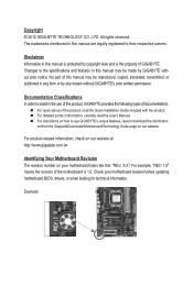
Table of Contents Box Contents...6 Optional Items...6 GA-880GMA-UD2H Motherboard Layout 7 GA-880GMA-UD2H Motherboard Block Diagram 8 Chapter 1 Hardware Installation 9 1-1 Installation Precautions 9 1-2 Product Specifications 10 1-3 Installing the CPU and CPU Cooler...8482; Configuration 19 1-7 Back Panel Connectors 20 1-8 Internal Connectors 23 Chapter 2 BIOS Setup 33 2-1 Startup Screen 34 2-2 The Main Menu 36 2-3 MB Intelligent Tweaker(M.I.T 38 2-4 Standard CMOS Features 45 2-5 Advanced BIOS Features 47 2-6 Integrated Peripherals 49 2-7 Power Management Setup 52 2-8 PnP/PCI ...
Table of Contents Box Contents...6 Optional Items...6 GA-880GMA-UD2H Motherboard Layout 7 GA-880GMA-UD2H Motherboard Block Diagram 8 Chapter 1 Hardware Installation 9 1-1 Installation Precautions 9 1-2 Product Specifications 10 1-3 Installing the CPU and CPU Cooler...8482; Configuration 19 1-7 Back Panel Connectors 20 1-8 Internal Connectors 23 Chapter 2 BIOS Setup 33 2-1 Startup Screen 34 2-2 The Main Menu 36 2-3 MB Intelligent Tweaker(M.I.T 38 2-4 Standard CMOS Features 45 2-5 Advanced BIOS Features 47 2-6 Integrated Peripherals 49 2-7 Power Management Setup 52 2-8 PnP/PCI ...
Manual
Page 5
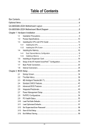
... 62 3-4 Contact...63 3-5 System...63 3-6 Download Center 64 3-7 New Utilities...64 Chapter 4 Unique Features 65 4-1 Xpress Recovery2 65 4-2 BIOS Update Utilities 68 4-2-1 Updating the BIOS with the Q-Flash Utility 68 4-2-2 Updating the BIOS with the @BIOS Utility 71 4-3 EasyTune 6...72 4-4 Easy Energy Saver 73 4-5 Q-Share...75 4-6 SMART Recovery 76 4-7 Auto Green...77 Chapter 5 Appendix...
... 62 3-4 Contact...63 3-5 System...63 3-6 Download Center 64 3-7 New Utilities...64 Chapter 4 Unique Features 65 4-1 Xpress Recovery2 65 4-2 BIOS Update Utilities 68 4-2-1 Updating the BIOS with the Q-Flash Utility 68 4-2-2 Updating the BIOS with the @BIOS Utility 71 4-3 EasyTune 6...72 4-4 Easy Energy Saver 73 4-5 Q-Share...75 4-6 SMART Recovery 76 4-7 Auto Green...77 Chapter 5 Appendix...
Manual
Page 8
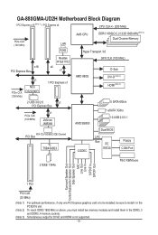
GA-880GMA-UD2H Motherboard Block Diagram 1 PCI Express x16 (Note 1) 1 PCI Express x4 CPU CLK+/- (200 MHz) PCIe CLK (100 MHz) LAN RJ45 AM3 CPU DDR3 1800(O.C.)/1333/... (100 MHz) D-Sub DVI-D (Note 3) HDMI (Note 3) 5 SATA 6Gb/s 1 eSATA 3Gb/s 10 USB 2.0/1.1 ATA-133/100/66/33 IDE Channel PCI Bus T.I. TSB43AB23 CODEC Dual BIOS LPC Bus iTE IT8720 Floppy COM Port 2 IEEE 1394a PS/2 KB/Mouse Surround Speaker Out Center/Subwoofer Speaker Out Side Speaker Out MIC Line Out...
GA-880GMA-UD2H Motherboard Block Diagram 1 PCI Express x16 (Note 1) 1 PCI Express x4 CPU CLK+/- (200 MHz) PCIe CLK (100 MHz) LAN RJ45 AM3 CPU DDR3 1800(O.C.)/1333/... (100 MHz) D-Sub DVI-D (Note 3) HDMI (Note 3) 5 SATA 6Gb/s 1 eSATA 3Gb/s 10 USB 2.0/1.1 ATA-133/100/66/33 IDE Channel PCI Bus T.I. TSB43AB23 CODEC Dual BIOS LPC Bus iTE IT8720 Floppy COM Port 2 IEEE 1394a PS/2 KB/Mouse Surround Speaker Out Center/Subwoofer Speaker Out Side Speaker Out MIC Line Out...
Manual
Page 12
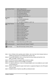
.../System fan fail warning CPU/System fan speed control (Note 6) 2 x 8 Mbit flash Use of licensed AWARD BIOS Support for DualBIOS™ PnP 1.0a, DMI 2.0, SM BIOS 2.4, ACPI 1.0b Support for @BIOS Support for Q-Flash Support for Xpress BIOS Rescue Support for Download Center Support for Xpress Install Support for Xpress Recovery2 Support for EasyTune...
.../System fan fail warning CPU/System fan speed control (Note 6) 2 x 8 Mbit flash Use of licensed AWARD BIOS Support for DualBIOS™ PnP 1.0a, DMI 2.0, SM BIOS 2.4, ACPI 1.0b Support for @BIOS Support for Q-Flash Support for Xpress BIOS Rescue Support for Download Center Support for Xpress Install Support for Xpress Recovery2 Support for EasyTune...

Manual
Page 16
... DDR3_2 DDR3_3 DDR3_4 Due to prevent hardware damage. • Memory modules have a foolproof design. Dual Channel mode cannot be used . (Go to GIGABYTE's website for optimum performance. Hardware Installation - 16 - It is recommended that memory of the same capacity, brand, speed, and chips be installed ...in only one DDR3 memory module is installed, the BIOS will double the original memory bandwidth. After the memory is installed. 2. A memory module can be used and installed in the same ...
... DDR3_2 DDR3_3 DDR3_4 Due to prevent hardware damage. • Memory modules have a foolproof design. Dual Channel mode cannot be used . (Go to GIGABYTE's website for optimum performance. Hardware Installation - 16 - It is recommended that memory of the same capacity, brand, speed, and chips be installed ...in only one DDR3 memory module is installed, the BIOS will double the original memory bandwidth. After the memory is installed. 2. A memory module can be used and installed in the same ...
Manual
Page 18
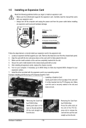
... straight out from the PCIEX16 Slot: Gently push back on the lever on the top edge of the PCI Express slot to make any required BIOS changes for your card. Install the driver provided with the expansion card in the slot. 3. Make sure the card is fully seated in your expansion... the PCIEX4 Slot: Press the white latch at the end of the card until it is fully inserted into the slot. 4. If necessary, go to BIOS Setup to release the card and then pull the card straight up from the chassis back panel. 2.
... straight out from the PCIEX16 Slot: Gently push back on the lever on the top edge of the PCI Express slot to make any required BIOS changes for your card. Install the driver provided with the expansion card in the slot. 3. Make sure the card is fully seated in your expansion... the PCIEX4 Slot: Press the white latch at the end of the card until it is fully inserted into the slot. 4. If necessary, go to BIOS Setup to release the card and then pull the card straight up from the chassis back panel. 2.
Manual
Page 19
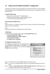
... Requirements - C. Set Internal Graphics Mode to the ATI Catalyst™ Control Center. Hardware Installation Read the following items under the Advanced BIOS Features menu: - An ATI Hybrid CrossFireX-supported graphics card (Note 2) B. Step 2: Plug the display cable into the onboard graphics ...D. Windows 7, Vista, or Windows XP (Note 1) operating system - An ATI Hybrid CrossFireX-supported motherboard and correct driver - BIOS Setup Enter BIOS Setup to 256MB or 512MB. (Note 3) - A. stalled. (Note 3) To change the Internal Graphics Mode or UMA Frame Buffer Size ...
... Requirements - C. Set Internal Graphics Mode to the ATI Catalyst™ Control Center. Hardware Installation Read the following items under the Advanced BIOS Features menu: - An ATI Hybrid CrossFireX-supported graphics card (Note 2) B. Step 2: Plug the display cable into the onboard graphics ...D. Windows 7, Vista, or Windows XP (Note 1) operating system - An ATI Hybrid CrossFireX-supported motherboard and correct driver - BIOS Setup Enter BIOS Setup to 256MB or 512MB. (Note 3) - A. stalled. (Note 3) To change the Internal Graphics Mode or UMA Frame Buffer Size ...

Manual
Page 21
... support D-Sub connection by adapter. (Note 2) Simultaneous output for DVI-D and HDMI is compatible with dual channel mode enabled • BIOS Setup: At least 256 MB of UMA Frame Buffer Size (refer to the recommended system requirements (or better) below shows the supported ...Blu-ray Discs: In order to get better playback quality, when playing the HD DVD or Blu-ray discs, refer to Chapter 2, "BIOS Setup," "Advanced BIOS Features," for more information) • Playback software: CyberLink PowerDVD 8.0 or later (Note: Please ensure Hardware Acceleration is enabled.) •...
... support D-Sub connection by adapter. (Note 2) Simultaneous output for DVI-D and HDMI is compatible with dual channel mode enabled • BIOS Setup: At least 256 MB of UMA Frame Buffer Size (refer to the recommended system requirements (or better) below shows the supported ...Blu-ray Discs: In order to get better playback quality, when playing the HD DVD or Blu-ray discs, refer to Chapter 2, "BIOS Setup," "Advanced BIOS Features," for more information) • Playback software: CyberLink PowerDVD 8.0 or later (Note: Please ensure Hardware Acceleration is enabled.) •...
Manual
Page 27
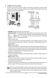
...activity LED, speaker and etc. Hardware Installation RESRES+ CICI+ PWR+ PWR- When connecting your system using the power switch (refer to Chapter 2, "BIOS Setup," "Power Management Setup," for information about beep codes. • HD (Hard Drive Activity LED, Blue) Connects to the hard drive activity LED... to this header, make sure the wire assignments and the pin assignments are matched correctly. - 27 - S1 Blinking tem is detected, the BIOS may differ by issuing a beep code. The LED is off when the system is reading or writing data. • RES (Reset Switch,...
...activity LED, speaker and etc. Hardware Installation RESRES+ CICI+ PWR+ PWR- When connecting your system using the power switch (refer to Chapter 2, "BIOS Setup," "Power Management Setup," for information about beep codes. • HD (Hard Drive Activity LED, Blue) Connects to the hard drive activity LED... to this header, make sure the wire assignments and the pin assignments are matched correctly. - 27 - S1 Blinking tem is detected, the BIOS may differ by issuing a beep code. The LED is off when the system is reading or writing data. • RES (Reset Switch,...
Manual
Page 31
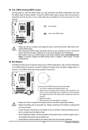
... the jumper cap from the battery holder and wait for one . Danger of purchase or local dealer if you are not able to Chapter 2, "BIOS Setup," for 5 seconds.) 3. Open: Normal Short: Clear CMOS Values • Always turn off your computer and unplug the power cord from the...like a screwdriver to touch the positive and negative terminals of the battery holder, making them short for BIOS configurations). 16) BAT (Battery) The battery provides power to keep the values (such as BIOS configurations, date, and time information) in accordance with an incorrect model. • Contact the place ...
... the jumper cap from the battery holder and wait for one . Danger of purchase or local dealer if you are not able to Chapter 2, "BIOS Setup," for 5 seconds.) 3. Open: Normal Short: Clear CMOS Values • Always turn off your computer and unplug the power cord from the...like a screwdriver to touch the positive and negative terminals of the battery holder, making them short for BIOS configurations). 16) BAT (Battery) The battery provides power to keep the values (such as BIOS configurations, date, and time information) in accordance with an incorrect model. • Contact the place ...
Manual
Page 33
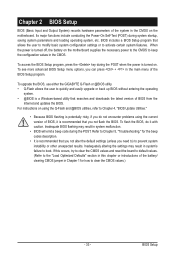
... utility that allows the user to modify basic system configuration settings or to keep the configuration values in the main menu of BIOS from the Internet and updates the BIOS. To upgrade the BIOS, use either the GIGABYTE Q-Flash or @BIOS utility. • Q-Flash allows the user to quickly and easily upgrade or back up...
... utility that allows the user to modify basic system configuration settings or to keep the configuration values in the main menu of BIOS from the Internet and updates the BIOS. To upgrade the BIOS, use either the GIGABYTE Q-Flash or @BIOS utility. • Q-Flash allows the user to quickly and easily upgrade or back up...
Manual
Page 34
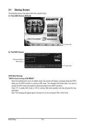
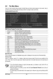
... running at IDE MODE!" Press to enable AHCI mode or to AHCI mode and enable hot plug functionality for the SATA connectors. Motherboard Model BIOS Version GA-880GMA-UD2H E1 . . . . : BIOS Setup : XpressRecovery2 : Boot Menu : Qflash 03/25/2010-RS880P-SB850-7A66BG0KC-00 Function Keys SATA Mode Message: "SATA is set to its default values...
... running at IDE MODE!" Press to enable AHCI mode or to AHCI mode and enable hot plug functionality for the SATA connectors. Motherboard Model BIOS Version GA-880GMA-UD2H E1 . . . . : BIOS Setup : XpressRecovery2 : Boot Menu : Qflash 03/25/2010-RS880P-SB850-7A66BG0KC-00 Function Keys SATA Mode Message: "SATA is set to its default values...

Manual
Page 35
... the device configured in Boot Menu is effective for subsequent access to show the BIOS POST screen at system startup, refer to the instructions on the Full Screen LOGO Show item on BIOS Setup settings. To show the BIOS POST screen. Function Keys: : POST SCREEN Press the key to Xpress Recovery2 during the... arrow key or the down arrow key to select the first boot device, then press to set the first boot device without having to enter BIOS Setup first. - 35 - In Boot Menu, use the up hard drive data using the driver disk, the key can access Boot Menu again to change...
... the device configured in Boot Menu is effective for subsequent access to show the BIOS POST screen at system startup, refer to the instructions on the Full Screen LOGO Show item on BIOS Setup settings. To show the BIOS POST screen. Function Keys: : POST SCREEN Press the key to Xpress Recovery2 during the... arrow key or the down arrow key to select the first boot device, then press to set the first boot device without having to enter BIOS Setup first. - 35 - In Boot Menu, use the up hard drive data using the driver disk, the key can access Boot Menu again to change...
Manual
Page 36
... Without Saving ESC: Quit F8: Q-Flash Select Item F10: Save & Exit Setup Change CPU's Clock & Voltage F11: Save CMOS to BIOS F12: Load CMOS from BIOS BIOS Setup Program Function Keys Move the selection bar to select an item Execute command or enter the submenu Main Menu: Exit the...description of a highlighted setup option is displayed on the screen. Press to exit the help screen (General Help) of function keys available for the menu. BIOS Setup - 36 - Submenu Help While in a submenu, press to display a help screen. 2-2 The Main Menu Once you want in the Main Menu...
... Without Saving ESC: Quit F8: Q-Flash Select Item F10: Save & Exit Setup Change CPU's Clock & Voltage F11: Save CMOS to BIOS F12: Load CMOS from BIOS BIOS Setup Program Function Keys Move the selection bar to select an item Execute command or enter the submenu Main Menu: Exit the...description of a highlighted setup option is displayed on the screen. Press to exit the help screen (General Help) of function keys available for the menu. BIOS Setup - 36 - Submenu Help While in a submenu, press to display a help screen. 2-2 The Main Menu Once you want in the Main Menu...

Manual
Page 37
...optimal-performance system operations. Set Supervisor Password Change, set , or disable password. First select the profile you to the system and BIOS Setup. A supervisor password allows you wish to load, then press to complete. MB Intelligent Tweaker(M.I.T.) Use this menu to configure ...61565; F12: Load CMOS from a profile created before, without the hassles of errors that stop the system boot, etc. Advanced BIOS Features Use this menu to configure the device boot order, advanced features available on the CPU, and the primary display adapter. ...
...optimal-performance system operations. Set Supervisor Password Change, set , or disable password. First select the profile you to the system and BIOS Setup. A supervisor password allows you wish to load, then press to complete. MB Intelligent Tweaker(M.I.T.) Use this menu to configure ...61565; F12: Load CMOS from a profile created before, without the hassles of errors that stop the system boot, etc. Advanced BIOS Features Use this menu to configure the device boot order, advanced features available on the CPU, and the primary display adapter. ...
Manual
Page 38
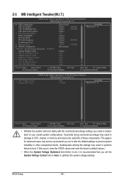
... F1: General Help F7: Optimized Defaults CMOS Setup Utility-Copyright (C) 1984-2010 Award Software MB Intelligent Tweaker(M.I .T.) } IGX Configuration CPU Clock Ratio CPU NorthBridge Freq. BIOS Setup - 38 -
... F1: General Help F7: Optimized Defaults CMOS Setup Utility-Copyright (C) 1984-2010 Award Software MB Intelligent Tweaker(M.I .T.) } IGX Configuration CPU Clock Ratio CPU NorthBridge Freq. BIOS Setup - 38 -
Manual
Page 39
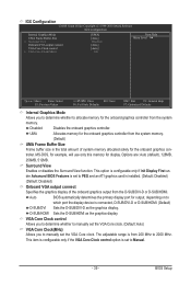
BIOS Setup Surround View Enables or disables the Surround View function. Options are: Auto (default), 128MB, 256MB, 512MB. VGA Core Clock control Allows you to determine ... onboard graphics controller from the D-SUB/DVI-D or D-SUB/HDMI. This option is configurable only if Init Display First under Advanced BIOS Features is set the VGA Core clock. Auto BIOS automatically determines the primary display port for output, depending on to which port the display device is the total amount of...
BIOS Setup Surround View Enables or disables the Surround View function. Options are: Auto (default), 128MB, 256MB, 512MB. VGA Core Clock control Allows you to determine ... onboard graphics controller from the D-SUB/DVI-D or D-SUB/HDMI. This option is configurable only if Init Display First under Advanced BIOS Features is set the VGA Core clock. Auto BIOS automatically determines the primary display port for output, depending on to which port the display device is the total amount of...

Manual
Page 40
Auto (default) allows the BIOS to X5.33. This option is configurable only when CPU Host Clock Control is highly recommended ... Link between the CPU and chipset. The adjustable range is dependent on the CPU being used . Auto BIOS will automatically adjust the HT Link Frequency. (Default) x1~x10 Sets HT Link Frequency to x1~x10 (200 MHz~2.0 GHz). ... (Default) 8 bit Sets HT Link Width to 8 bit. 16 bit Sets HT Link Width to 16 bit. Auto lets BIOS automatically set the memory clock. X4.00 Sets Memory Clock to X8.00. CPU Clock Ratio Allows you to alter the clock ratio...
Auto (default) allows the BIOS to X5.33. This option is configurable only when CPU Host Clock Control is highly recommended ... Link between the CPU and chipset. The adjustable range is dependent on the CPU being used . Auto BIOS will automatically adjust the HT Link Frequency. (Default) x1~x10 Sets HT Link Frequency to x1~x10 (200 MHz~2.0 GHz). ... (Default) 8 bit Sets HT Link Width to 8 bit. 16 bit Sets HT Link Width to 16 bit. Auto lets BIOS automatically set the memory clock. X4.00 Sets Memory Clock to X8.00. CPU Clock Ratio Allows you to alter the clock ratio...

Manual
Page 41
...) DDR3 Timing Items Manual allows all DDR3 Timing items below to set memory control mode. RAS to CAS R/W Delay Options are : Auto (default), 4T~12T. BIOS Setup Options are: Auto (default), Manual. Auto -- --
...) DDR3 Timing Items Manual allows all DDR3 Timing items below to set memory control mode. RAS to CAS R/W Delay Options are : Auto (default), 4T~12T. BIOS Setup Options are: Auto (default), Manual. Auto -- --


