Manual
Page 4
Table of Contents Box Contents...6 Optional Items...6 GA-880GMA-UD2H Motherboard Layout 7 GA-880GMA-UD2H Motherboard Block Diagram 8 Chapter 1 Hardware Installation 9 1-1 Installation Precautions 9 1-2 Product Specifications 10 1-3 Installing the CPU and CPU Cooler 13 1-3-1 Installing the CPU 13 1-3-2 Installing the CPU Cooler 15 1-4 Installing the Memory 16 1-4-1 Dual Channel Memory Configuration 16 1-4-2 Installing a Memory 17 1-5 Installing an Expansion Card 18 1-6 Setup...
Table of Contents Box Contents...6 Optional Items...6 GA-880GMA-UD2H Motherboard Layout 7 GA-880GMA-UD2H Motherboard Block Diagram 8 Chapter 1 Hardware Installation 9 1-1 Installation Precautions 9 1-2 Product Specifications 10 1-3 Installing the CPU and CPU Cooler 13 1-3-1 Installing the CPU 13 1-3-2 Installing the CPU Cooler 15 1-4 Installing the Memory 16 1-4-1 Dual Channel Memory Configuration 16 1-4-2 Installing a Memory 17 1-5 Installing an Expansion Card 18 1-6 Setup...
Manual
Page 8
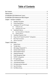
... (Note 2) To reach DDR3 1800 MHz or above, you must install two memory modules and install them in the DDR3_3 and DDR3_4 memory sockets. (Note 3) Simultaneous output for DVI-D and HDMI is not supported. - 8 - GA-880GMA-UD2H Motherboard Block Diagram 1 PCI Express x16 (Note 1) 1 PCI Express x4 CPU... CLK+/- (200 MHz) PCIe CLK (100 MHz) LAN RJ45 AM3 CPU DDR3 1800(O.C.)/1333/1066 MHz(Note 2) Dual Channel Memory Hyper Transport 3.0 x16 PCI Express Bus Realtek RTL8111D...
... (Note 2) To reach DDR3 1800 MHz or above, you must install two memory modules and install them in the DDR3_3 and DDR3_4 memory sockets. (Note 3) Simultaneous output for DVI-D and HDMI is not supported. - 8 - GA-880GMA-UD2H Motherboard Block Diagram 1 PCI Express x16 (Note 1) 1 PCI Express x4 CPU... CLK+/- (200 MHz) PCIe CLK (100 MHz) LAN RJ45 AM3 CPU DDR3 1800(O.C.)/1333/1066 MHz(Note 2) Dual Channel Memory Hyper Transport 3.0 x16 PCI Express Bus Realtek RTL8111D...
Manual
Page 9
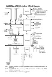
... components. • When connecting hardware components to the internal connectors on the computer power during the installation process can become damaged as a motherboard, CPU or memory. ponents such as a result of an antistatic pad or within the computer casing. • Do not place the computer system on an uneven surface. •...
... components. • When connecting hardware components to the internal connectors on the computer power during the installation process can become damaged as a motherboard, CPU or memory. ponents such as a result of an antistatic pad or within the computer casing. • Do not place the computer system on an uneven surface. •...
Manual
Page 10
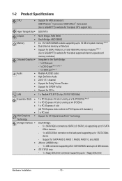
...; II processor/ AMD Athlon™ II processor (Go to GIGABYTE's website for the latest CPU support list.) Hyper Transport Bus 5200 MT/s Chipset Memory Onboard Graphics Audio ...5V DDR3 DIMM sockets supporting up to 16 GB of system memory (Note 1) Dual channel memory architecture Support for DDR3 1800(O.C.)/1333/1066 MHz memory modules (Note 2) (Go to GIGABYTE's website for the latest supported memory speeds and memory modules.) Integrated in the North Bridge: - 1 x ...
...; II processor/ AMD Athlon™ II processor (Go to GIGABYTE's website for the latest CPU support list.) Hyper Transport Bus 5200 MT/s Chipset Memory Onboard Graphics Audio ...5V DDR3 DIMM sockets supporting up to 16 GB of system memory (Note 1) Dual channel memory architecture Support for DDR3 1800(O.C.)/1333/1066 MHz memory modules (Note 2) (Go to GIGABYTE's website for the latest supported memory speeds and memory modules.) Integrated in the North Bridge: - 1 x ...
Manual
Page 12
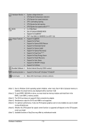
...Form Factor w Micro ATX Form Factor; 24.4cm x 24.4cm (Note 1) Due to Windows 32-bit operating system limitation, when more than 4 GB of physical memory is installed, the actual memory size displayed will be less than 4 GB. (Note 2) To reach DDR3 1800 MHz or above, you must install two... memory modules and install them in the DDR3_3 and DDR3_4 memory sockets. (Note 3) The DVI-D port does not support D-Sub connection by adapter. (Note 4) Simultaneous output for DVI-D and HDMI is not supported. (...
...Form Factor w Micro ATX Form Factor; 24.4cm x 24.4cm (Note 1) Due to Windows 32-bit operating system limitation, when more than 4 GB of physical memory is installed, the actual memory size displayed will be less than 4 GB. (Note 2) To reach DDR3 1800 MHz or above, you must install two... memory modules and install them in the DDR3_3 and DDR3_4 memory sockets. (Note 3) The DVI-D port does not support D-Sub connection by adapter. (Note 4) Simultaneous output for DVI-D and HDMI is not supported. (...
Manual
Page 13
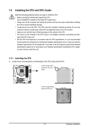
...cord from the power outlet before you begin to install the CPU: • Make sure that the motherboard supports the CPU. (Go to GIGABYTE's website for the latest CPU support list.) • Always turn on the computer if the CPU cooler is not recommended that the system bus... frequency be inserted if oriented incorrectly. (Or you wish to your hardware specifications including the CPU, graphics card, memory, hard drive, etc. 1-3-1 Installing the CPU A. Hardware Installation A Small Triangle Mark Denotes Pin One of the CPU socket and the CPU. ...
...cord from the power outlet before you begin to install the CPU: • Make sure that the motherboard supports the CPU. (Go to GIGABYTE's website for the latest CPU support list.) • Always turn on the computer if the CPU cooler is not recommended that the system bus... frequency be inserted if oriented incorrectly. (Or you wish to your hardware specifications including the CPU, graphics card, memory, hard drive, etc. 1-3-1 Installing the CPU A. Hardware Installation A Small Triangle Mark Denotes Pin One of the CPU socket and the CPU. ...

Manual
Page 16
...When enabling Dual Channel mode with two or four memory modules, it is recommended that memory of the same capacity, brand, speed, and chips be used . (Go to GIGABYTE's website for optimum performance. If you begin to prevent hardware damage. • Memory modules have a foolproof design. DS/SS DS/...SS Four Modules DS/SS DS/SS DS/SS DS/SS (SS=Single-Sided, DS=Double-Sided, "- -"=No Memory) DDR3_1 DDR3_2 DDR3_3 DDR3_4...
...When enabling Dual Channel mode with two or four memory modules, it is recommended that memory of the same capacity, brand, speed, and chips be used . (Go to GIGABYTE's website for optimum performance. If you begin to prevent hardware damage. • Memory modules have a foolproof design. DS/SS DS/...SS Four Modules DS/SS DS/SS DS/SS DS/SS (SS=Single-Sided, DS=Double-Sided, "- -"=No Memory) DDR3_1 DDR3_2 DDR3_3 DDR3_4...
Manual
Page 17
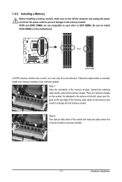
...the computer and unplug the power cord from the power outlet to prevent damage to correctly install your fingers on the memory and insert it can only fit in the memory sockets. DDR3 and DDR2 DIMMs are not compatible to each other or DDR DIMMs. Be sure to install DDR3 ...Follow the steps below to the memory module. Step 1: Note the orientation of the memory, push down on the top edge of the memory module. Step 2: The clips at both ends of the memory socket. Notch DDR3 DIMM A DDR3 memory module has a notch, so it vertically into place when the memory module is securely inserted. -...
...the computer and unplug the power cord from the power outlet to prevent damage to correctly install your fingers on the memory and insert it can only fit in the memory sockets. DDR3 and DDR2 DIMMs are not compatible to each other or DDR DIMMs. Be sure to install DDR3 ...Follow the steps below to the memory module. Step 1: Note the orientation of the memory, push down on the top edge of the memory module. Step 2: The clips at both ends of the memory socket. Notch DDR3 DIMM A DDR3 memory module has a notch, so it vertically into place when the memory module is securely inserted. -...

Manual
Page 21
... quality, when playing the HD DVD or Blu-ray discs, refer to prevent an electrical short inside the cable connector. - 21 - A. The table below . • Memory: Two 1 GB DDR3 1066 memory modules with SATA 1.5Gb/s standard.
... quality, when playing the HD DVD or Blu-ray discs, refer to prevent an electrical short inside the cable connector. - 21 - A. The table below . • Memory: Two 1 GB DDR3 1066 memory modules with SATA 1.5Gb/s standard.

Manual
Page 37
... effect. First enter the profile name (to erase the default profile name, use this function to load the BIOS settings from BIOS If your CPU, memory, etc. Standard CMOS Features Use this menu to configure the system time and date, hard drive types, floppy disk drive types, and the type...
... effect. First enter the profile name (to erase the default profile name, use this function to load the BIOS settings from BIOS If your CPU, memory, etc. Standard CMOS Features Use this menu to configure the system time and date, hard drive types, floppy disk drive types, and the type...
Manual
Page 38
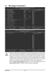
... system's failure to boot. CPU Host Clock Control x CPU Frequency(MHz) PCIE Clock(MHz) HT Link Width HT Link Frequency Set Memory Clock x Memory Clock } DRAM Configuration ******** System Voltage Optimized ******** System Voltage Control x CPU PLL Voltage Control x DRAM Voltage Control x DDR VTT ...BIOS Setup - 38 - This page is recommended that you set the System Voltage Control item to Auto to CPU, chipset, or memory and reduce the useful life of these components. 2-3 MB Intelligent Tweaker(M.I.T.) CMOS Setup Utility-Copyright (C) 1984-2010 Award Software MB Intelligent...
... system's failure to boot. CPU Host Clock Control x CPU Frequency(MHz) PCIE Clock(MHz) HT Link Width HT Link Frequency Set Memory Clock x Memory Clock } DRAM Configuration ******** System Voltage Optimized ******** System Voltage Control x CPU PLL Voltage Control x DRAM Voltage Control x DDR VTT ...BIOS Setup - 38 - This page is recommended that you set the System Voltage Control item to Auto to CPU, chipset, or memory and reduce the useful life of these components. 2-3 MB Intelligent Tweaker(M.I.T.) CMOS Setup Utility-Copyright (C) 1984-2010 Award Software MB Intelligent...
Manual
Page 39
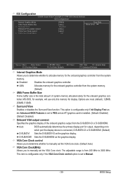
... Setup MS-DOS, for example, will use only this memory for the onboard graphics controller from the system memory. (Default) UMA Frame Buffer Size Frame buffer size is the total amount of the onboard graphics output from the D-SUB/DVI-D or D-SUB/HDMI. D-... graphics card is installed. (Default: Disabled) (Default: Disabled) Onboard VGA output connect Specifies the graphics display of system memory allocated solely for output, depending on to manually set to allocate memory for display. This item is configurable only if the VGA Core Clock control option is set the VGA Core clock...
... Setup MS-DOS, for example, will use only this memory for the onboard graphics controller from the system memory. (Default) UMA Frame Buffer Size Frame buffer size is the total amount of the onboard graphics output from the D-SUB/DVI-D or D-SUB/HDMI. D-... graphics card is installed. (Default: Disabled) (Default: Disabled) Onboard VGA output connect Specifies the graphics display of system memory allocated solely for output, depending on to manually set to allocate memory for display. This item is configurable only if the VGA Core Clock control option is set the VGA Core clock...

Manual
Page 40
... The adjustable range is dependent on the CPU being used . Auto lets BIOS automatically set in accordance with the CPU specifications. X6.66 Sets Memory Clock to 150 MHz. CPU Host Clock Control Enables or disables the control of CPU host clock. CPU Frequency(MHz) Allows you to automatically ...the HT Link Width. (Default) 8 bit Sets HT Link Width to 8 bit. 16 bit Sets HT Link Width to manually set the memory clock. X4.00 Sets Memory Clock to x1~x10 (200 MHz~2.0 GHz). Allows you to Manual. The adjustable range is dependent on the CPU being used . The ...
... The adjustable range is dependent on the CPU being used . Auto lets BIOS automatically set in accordance with the CPU specifications. X6.66 Sets Memory Clock to 150 MHz. CPU Host Clock Control Enables or disables the control of CPU host clock. CPU Frequency(MHz) Allows you to automatically ...the HT Link Width. (Default) 8 bit Sets HT Link Width to 8 bit. 16 bit Sets HT Link Width to manually set the memory clock. X4.00 Sets Memory Clock to x1~x10 (200 MHz~2.0 GHz). Allows you to Manual. The adjustable range is dependent on the CPU being used . The ...

Manual
Page 41
... Time x Row Cycle Time x RAS to single dual-channel. Options are : Auto (default), 4T~12T. CAS# latency Options are : Auto (default), Manual. Ganged Sets memory control mode to RAS Delay **DCTs Drive Strength** ProcOdt(ohms) DQS Drive Strength [Unganged] [Auto] SPD Auto Auto 9T 9T Auto 9T 9T Auto 9T... 9T Auto 24T 24T Auto -- -- Unganged Sets memory control mode to two single-channel. (Default) DDR3 Timing Items Manual allows all DDR3 Timing items below to set...
... Time x Row Cycle Time x RAS to single dual-channel. Options are : Auto (default), 4T~12T. CAS# latency Options are : Auto (default), Manual. Ganged Sets memory control mode to RAS Delay **DCTs Drive Strength** ProcOdt(ohms) DQS Drive Strength [Unganged] [Auto] SPD Auto Auto 9T 9T Auto 9T 9T Auto 9T... 9T Auto 24T 24T Auto -- -- Unganged Sets memory control mode to two single-channel. (Default) DDR3 Timing Items Manual allows all DDR3 Timing items below to set...
Manual
Page 43
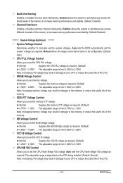
...(Default) 1.450V ~ 2.100V The adjustable range is from 1.300V to 1.100V. DRAM Voltage Control Allows you to 2.100V. Note: Increasing memory voltage may result in damage to 3.100V. Normal Supplies the VCC18 voltage as required. (Default) 2.220V ~ 3.100V The adjustable range is ...in damage to set the VCC18 voltage. VCC18 Voltage Control Allows you to your CPU or reduce the useful life of the memory to increase memory performance and stability. (Default: Enabled) ******** System Voltage Optimized ******** System Voltage Control Determines whether to set the CPU North...
...(Default) 1.450V ~ 2.100V The adjustable range is from 1.300V to 1.100V. DRAM Voltage Control Allows you to 2.100V. Note: Increasing memory voltage may result in damage to 3.100V. Normal Supplies the VCC18 voltage as required. (Default) 2.220V ~ 3.100V The adjustable range is ...in damage to set the VCC18 voltage. VCC18 Voltage Control Allows you to your CPU or reduce the useful life of the memory to increase memory performance and stability. (Default: Enabled) ******** System Voltage Optimized ******** System Voltage Control Determines whether to set the CPU North...
Manual
Page 45
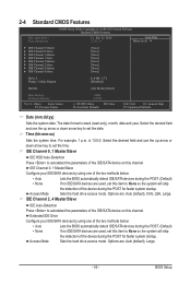
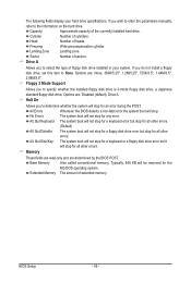
... 4 Master } IDE Channel 4 Slave [None] [None] [None] [None] [None] [None] [None] [None] Drive A Floppy 3 Mode Support [1.44M, 3.5"] [Disabled] Halt On [All, But Keyboard] Base Memory Extended Memory 640K 1022M Move Enter: Select F5: Previous Values +/-/PU/PD: Value F10: Save F6: Fail-Safe Defaults ESC: Exit F1: General Help F7: Optimized Defaults...
... 4 Master } IDE Channel 4 Slave [None] [None] [None] [None] [None] [None] [None] [None] Drive A Floppy 3 Mode Support [1.44M, 3.5"] [Disabled] Halt On [All, But Keyboard] Base Memory Extended Memory 640K 1022M Move Enter: Select F5: Previous Values +/-/PU/PD: Value F10: Save F6: Fail-Safe Defaults ESC: Exit F1: General Help F7: Optimized Defaults...
Manual
Page 46
..., 360K/5.25", 1.2M/5.25", 720K/3.5", 1.44M/3.5", 2.88M/3.5". If you wish to enter the parameters manually, refer to select the type of sectors. Base Memory Also called conventional memory. Landing Zone Landing zone. Floppy 3 Mode Support Allows you to the information on the hard drive. All, But Keyboard The system boot will not...
..., 360K/5.25", 1.2M/5.25", 720K/3.5", 1.44M/3.5", 2.88M/3.5". If you wish to enter the parameters manually, refer to select the type of sectors. Base Memory Also called conventional memory. Landing Zone Landing zone. Floppy 3 Mode Support Allows you to the information on the hard drive. All, But Keyboard The system boot will not...
Manual
Page 53
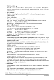
... by keyboard, and wake on LAN. (Note) Supported on Windows 7/Vista operating system only. - 53 - Any KEY Press any key on the keyboard to accept. Memory The system returns to be awakened from a PCI or PCIe device. BIOS Setup Power On By Keyboard Allows the system to its last known awake...
... by keyboard, and wake on LAN. (Note) Supported on Windows 7/Vista operating system only. - 53 - Any KEY Press any key on the keyboard to accept. Memory The system returns to be awakened from a PCI or PCIe device. BIOS Setup Power On By Keyboard Allows the system to its last known awake...
Manual
Page 65
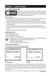
... first and second SATA connectors, the hard drive on your system soon after the operating system and drivers are installed. • The amount of system memory • VESA compatible graphics card • Windows XP with Xpress Recovery cannot be restored using Xpress Recovery2. • USB hard drives are not supported. actual...
... first and second SATA connectors, the hard drive on your system soon after the operating system and drivers are installed. • The amount of system memory • VESA compatible graphics card • Windows XP with Xpress Recovery cannot be restored using Xpress Recovery2. • USB hard drives are not supported. actual...
Manual
Page 72
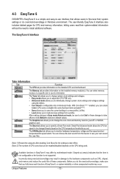
...may result in Windows environment. Unique Features - 72 - The user-friendly EasyTune 6 interface also includes tabbed pages for CPU and memory information, letting users read their system settings or do the overclock/overvoltage, make sure that you to see its information. You ... Available functions in Advanced mode. The HW Monitor tab allows you to be sure to click Set for these components. 4-3 EasyTune 6 GIGABYTE's EasyTune 6 is a simple and easy-to-use your ATI or NVIDIA graphics card. The EasyTune 6 Interface Tabs Information Tab Function The...
...may result in Windows environment. Unique Features - 72 - The user-friendly EasyTune 6 interface also includes tabbed pages for CPU and memory information, letting users read their system settings or do the overclock/overvoltage, make sure that you to see its information. You ... Available functions in Advanced mode. The HW Monitor tab allows you to be sure to click Set for these components. 4-3 EasyTune 6 GIGABYTE's EasyTune 6 is a simple and easy-to-use your ATI or NVIDIA graphics card. The EasyTune 6 Interface Tabs Information Tab Function The...


