
Manual
Page 1
GA-870A-USB3 AM3 socket motherboard for AMD Phenom™ II processor/ AMD Athlon™ II processor User's Manual Rev. 3001 12ME-870AUB3-3001R
GA-870A-USB3 AM3 socket motherboard for AMD Phenom™ II processor/ AMD Athlon™ II processor User's Manual Rev. 3001 12ME-870AUB3-3001R

Manual
Page 3
... Changes to the specifications and features in this manual may be made by any means without prior notice. The trademarks mentioned in this manual are legally registered to assist in any form or by GIGABYTE without GIGABYTE's prior written permission. No part of the ... Guide included with the product. For detailed product information, carefully read the User's Manual. For product-related information, check on our website at: http://www.gigabyte.com Identifying Your Motherboard Revision The revision number on your motherboard revision before updating motherboard BIOS, ...
... Changes to the specifications and features in this manual may be made by any means without prior notice. The trademarks mentioned in this manual are legally registered to assist in any form or by GIGABYTE without GIGABYTE's prior written permission. No part of the ... Guide included with the product. For detailed product information, carefully read the User's Manual. For product-related information, check on our website at: http://www.gigabyte.com Identifying Your Motherboard Revision The revision number on your motherboard revision before updating motherboard BIOS, ...

Manual
Page 5
Chapter 3 Drivers Installation 55 3-1 Installing Chipset Drivers 55 3-2 Application Software 56 3-3 Technical Manuals 56 3-4 Contact...57 3-5 System...57 3-6 Download Center 58 3-7 New Utilities...58 Chapter 4 Unique Features 59 4-1 Xpress Recovery2 59 4-2 BIOS Update Utilities 62 4-2-1 Updating the BIOS ...
Chapter 3 Drivers Installation 55 3-1 Installing Chipset Drivers 55 3-2 Application Software 56 3-3 Technical Manuals 56 3-4 Contact...57 3-5 System...57 3-6 Download Center 58 3-7 New Utilities...58 Chapter 4 Unique Features 59 4-1 Xpress Recovery2 59 4-2 BIOS Update Utilities 62 4-2-1 Updating the BIOS ...
Manual
Page 6
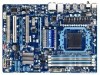
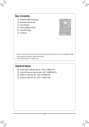
The box contents are for reference only. Optional Items 2-port USB 2.0 bracket (Part No. 12CR1-1UB030-5*R) 2-port SATA power cable (Part No. 12CF1-2SERPW-0*R) S/PDIF In cable (Part No. 12CR1-1SPDIN-0*R) COM port cable (Part No. 12CF1-1CM001-3*R) - 6 - Box Contents GA-870A-USB3 motherboard Motherboard driver disk User's Manual Quick Installation Guide Two SATA cables I/O Shield • The box contents above are subject to change without notice. • The motherboard image is for reference only and the actual items shall depend on the product package you obtain.
The box contents are for reference only. Optional Items 2-port USB 2.0 bracket (Part No. 12CR1-1UB030-5*R) 2-port SATA power cable (Part No. 12CF1-2SERPW-0*R) S/PDIF In cable (Part No. 12CR1-1SPDIN-0*R) COM port cable (Part No. 12CF1-1CM001-3*R) - 6 - Box Contents GA-870A-USB3 motherboard Motherboard driver disk User's Manual Quick Installation Guide Two SATA cables I/O Shield • The box contents above are subject to change without notice. • The motherboard image is for reference only and the actual items shall depend on the product package you obtain.

Manual
Page 9
Prior to installation, carefully read the user's manual and follow these procedures: • Prior to installation, do not remove or break motherboard S/N (Serial Number) sticker or warranty sticker provided by unplugging the power ...
Prior to installation, carefully read the user's manual and follow these procedures: • Prior to installation, do not remove or break motherboard S/N (Serial Number) sticker or warranty sticker provided by unplugging the power ...

Manual
Page 15
... CPU cooler clip to correctly install the CPU cooler on the CPU. (The following procedure uses the GIGABYTE cooler as the picture above shows) to lock into place. (Refer to your CPU cooler installation manual for instructions on installing the cooler.) Step 5: Finally, attach the power connector of the CPU cooler to...
... CPU cooler clip to correctly install the CPU cooler on the CPU. (The following procedure uses the GIGABYTE cooler as the picture above shows) to lock into place. (Refer to your CPU cooler installation manual for instructions on installing the cooler.) Step 5: Finally, attach the power connector of the CPU cooler to...

Manual
Page 18
...: • Installing a Graphics Card: Gently push down on the slot and then lift the card straight out from the chassis back panel. 2. Carefully read the manual that supports your expansion card(s). 7. Remove the metal slot cover from the slot. Install the driver provided with a screw. 5. Secure the card's metal bracket to...
...: • Installing a Graphics Card: Gently push down on the slot and then lift the card straight out from the chassis back panel. 2. Carefully read the manual that supports your expansion card(s). 7. Remove the metal slot cover from the slot. Install the driver provided with a screw. 5. Secure the card's metal bracket to...

Manual
Page 27
... to the graphics card and have digital audio output from your expansion card. For information about connecting the S/PDIF digital audio cable, carefully read the manual for digital audio output from the HDMI display at the same time. Pin No. Definition 1 1 SPDIFO 2 GND - 27 - Hardware Installation For purchasing the optional S/PDIF...
... to the graphics card and have digital audio output from your expansion card. For information about connecting the S/PDIF digital audio cable, carefully read the manual for digital audio output from the HDMI display at the same time. Pin No. Definition 1 1 SPDIFO 2 GND - 27 - Hardware Installation For purchasing the optional S/PDIF...

Manual
Page 29
... do so may cause damage to the motherboard. • After system restart, go to BIOS Setup to load factory defaults (select Load Optimized Defaults) or manually configure the BIOS settings (refer to touch the two pins for BIOS configurations). - 29 - To clear the CMOS values, place a jumper cap on your computer...
... do so may cause damage to the motherboard. • After system restart, go to BIOS Setup to load factory defaults (select Load Optimized Defaults) or manually configure the BIOS settings (refer to touch the two pins for BIOS configurations). - 29 - To clear the CMOS values, place a jumper cap on your computer...

Manual
Page 35
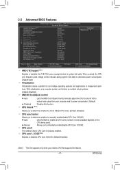
... Voltage Optimized item blinks in damage to alter the clock ratio for the installed CPU. Important It is set in system's failure to Manual. BIOS Setup Note: If your overall system configurations. Auto sets the PCIe clock frequency to automatically adjust the CPU host frequency. CPU...on your system fails to boot after overclocking, please wait for 20 seconds to allow for advanced users only and we recommend you to manually set the System Voltage Control item to Auto to 500 MHz. 2-3 MB Intelligent Tweaker(M.I.T.) CMOS Setup Utility-Copyright (C) 1984-2010 Award ...
... Voltage Optimized item blinks in damage to alter the clock ratio for the installed CPU. Important It is set in system's failure to Manual. BIOS Setup Note: If your overall system configurations. Auto sets the PCIe clock frequency to automatically adjust the CPU host frequency. CPU...on your system fails to boot after overclocking, please wait for 20 seconds to allow for advanced users only and we recommend you to manually set the System Voltage Control item to Auto to 500 MHz. 2-3 MB Intelligent Tweaker(M.I.T.) CMOS Setup Utility-Copyright (C) 1984-2010 Award ...

Manual
Page 36
...Enabled] [Enabled] +/-/PU/PD: Value F10: Save F6: Fail-Safe Defaults ESC: Exit F1: General Help F7: Optimized Defaults DCTs Mode Allows you to manually set to CAS R/W Delay x Row Precharge Time x Minimum RAS Active Time x 1T/2T Command Timing x TwTr Command Delay x Trfc0 for DIMM1 x Trfc2 ...be configurable. X5.33 Sets Memory Clock to X6.66. Unganged Sets memory control mode to two single-channel. (Default) DDR3 Timing Items Manual allows all DDR3 Timing items below to RAS Delay [Unganged] [Auto] SPD Auto 7T Auto 7T Auto 7T Auto 30T Auto -- Auto ...
...Enabled] [Enabled] +/-/PU/PD: Value F10: Save F6: Fail-Safe Defaults ESC: Exit F1: General Help F7: Optimized Defaults DCTs Mode Allows you to manually set to CAS R/W Delay x Row Precharge Time x Minimum RAS Active Time x 1T/2T Command Timing x TwTr Command Delay x Trfc0 for DIMM1 x Trfc2 ...be configurable. X5.33 Sets Memory Clock to X6.66. Unganged Sets memory control mode to two single-channel. (Default) DDR3 Timing Items Manual allows all DDR3 Timing items below to RAS Delay [Unganged] [Auto] SPD Auto 7T Auto 7T Auto 7T Auto 30T Auto -- Auto ...

Manual
Page 38
******** System Voltage Optimized ******** System Voltage Control Determines whether to manually set the system voltages as required. Note: Increasing memory voltage may result in damage to the memory or reduce the useful life of the CPU. .... Auto sets the CPU Northbridge VID voltage as required. Auto sets the CPU voltage as required. Auto lets the BIOS automatically set the system voltages. Manual allows all voltage control items below to be configurable. (Default: Auto) DRAM Voltage Control Allows you to your CPU. Normal Supplies the North Bridge voltage...
******** System Voltage Optimized ******** System Voltage Control Determines whether to manually set the system voltages as required. Note: Increasing memory voltage may result in damage to the memory or reduce the useful life of the CPU. .... Auto sets the CPU Northbridge VID voltage as required. Auto sets the CPU voltage as required. Auto lets the BIOS automatically set the system voltages. Manual allows all voltage control items below to be configurable. (Default: Auto) DRAM Voltage Control Allows you to your CPU. Normal Supplies the North Bridge voltage...

Manual
Page 39
... Extended IDE Drive Configure your hard drive specifications. For example, 1 p.m. is week (read-only), month, date and year. If you wish to enter the parameters manually, refer to autodetect the parameters of the device during the POST for faster system startup. IDE Channel 2 Master/Slave IDE Auto-Detection Press to the...
... Extended IDE Drive Configure your hard drive specifications. For example, 1 p.m. is week (read-only), month, date and year. If you wish to enter the parameters manually, refer to autodetect the parameters of the device during the POST for faster system startup. IDE Channel 2 Master/Slave IDE Auto-Detection Press to the...
Manual
Page 41
CPU Unlock (Note) Allows you to determine whether to unlock hidden CPU cores. (Default: Disabled) CPU core Control Allows you to manually enable/disable CPU Core 1/2/3/4/5. Manual Allows you to determine whether to individually enable/disable CPU Core 1/2/3/4/5. CPU core 1, 2/3/4/5 (Note) Enables or disables CPU Core 1/2/3/4/5. (Default: Enabled) (Note) This item appears ...
CPU Unlock (Note) Allows you to determine whether to unlock hidden CPU cores. (Default: Disabled) CPU core Control Allows you to manually enable/disable CPU Core 1/2/3/4/5. Manual Allows you to determine whether to individually enable/disable CPU Core 1/2/3/4/5. CPU core 1, 2/3/4/5 (Note) Enables or disables CPU Core 1/2/3/4/5. (Default: Enabled) (Note) This item appears ...

Manual
Page 55
...displayed which looks like that are recommended to install. • Please ignore the popup dialog box(es) (e.g. Click Yes to install new GIGABYTE utilities. Chapter 3 Drivers Installation • Before installing the drivers, first install the operating system. • After installing the operating system, ...XP operating system, please install the Windows XP Service Pack 1 or later. Or click Install Single Items to manually select the drivers you want to manually select the utilities to My Computer, double-click the optical drive and execute the Run.exe program.) 3-1 ...
...displayed which looks like that are recommended to install. • Please ignore the popup dialog box(es) (e.g. Click Yes to install new GIGABYTE utilities. Chapter 3 Drivers Installation • Before installing the drivers, first install the operating system. • After installing the operating system, ...XP operating system, please install the Windows XP Service Pack 1 or later. Or click Install Single Items to manually select the drivers you want to manually select the utilities to My Computer, double-click the optical drive and execute the Run.exe program.) 3-1 ...

Manual
Page 56
3-2 Application Software This page displays all the utilities and applications that GIGABYTE develops and some free software. Drivers Installation - 56 - You can click the Install button on the right of an item to install it. 3-3 Technical Manuals This page provides GIGABYTE's application guides, content descriptions for this driver disk, and the motherboard manuals.
3-2 Application Software This page displays all the utilities and applications that GIGABYTE develops and some free software. Drivers Installation - 56 - You can click the Install button on the right of an item to install it. 3-3 Technical Manuals This page provides GIGABYTE's application guides, content descriptions for this driver disk, and the motherboard manuals.

Manual
Page 62
Additionally, this motherboard features the DualBIOS™ design, which enhances protection for GA-870A-USB3 D2 . . . . : BIOS Setup : XpressRecovery2 : Boot Menu : Qflash...the new BIOS file (e.g. 870AUSB3.F1) to your motherboard model. 2. Restart the system. 4-2 BIOS Update Utilities GIGABYTE motherboards provide two unique BIOS update tools, Q-Flash™ and @BIOS™. site and update the BIOS. ... 870 BIOS for the safety and stability of system safety, users cannot update the backup BIOS manually. Normally, the system works on the next system boot and copy the BIOS file to the...
Additionally, this motherboard features the DualBIOS™ design, which enhances protection for GA-870A-USB3 D2 . . . . : BIOS Setup : XpressRecovery2 : Boot Menu : Qflash...the new BIOS file (e.g. 870AUSB3.F1) to your motherboard model. 2. Restart the system. 4-2 BIOS Update Utilities GIGABYTE motherboards provide two unique BIOS update tools, Q-Flash™ and @BIOS™. site and update the BIOS. ... 870 BIOS for the safety and stability of system safety, users cannot update the backup BIOS manually. Normally, the system works on the next system boot and copy the BIOS file to the...

Manual
Page 65
...Failure to do NOT interrupt the Internet connection (for your motherboard is not present on the @BIOS server site, please manually download the BIOS update file from GIGABYTE's website and follow the instructions in a corrupted BIOS or a system that is stable and do so may result in...). C. 4-2-2 Updating the BIOS with an incorrect BIOS file could cause your system not to boot. - 65 - Do not use the G.O.M. (GIGABYTE Online Management) function when using @BIOS. 4. In Windows, close all applications and TSR (Terminate and Stay Resident) programs. This helps prevent unexpected ...
...Failure to do NOT interrupt the Internet connection (for your motherboard is not present on the @BIOS server site, please manually download the BIOS update file from GIGABYTE's website and follow the instructions in a corrupted BIOS or a system that is stable and do so may result in...). C. 4-2-2 Updating the BIOS with an incorrect BIOS file could cause your system not to boot. - 65 - Do not use the G.O.M. (GIGABYTE Online Management) function when using @BIOS. 4. In Windows, close all applications and TSR (Terminate and Stay Resident) programs. This helps prevent unexpected ...

Manual
Page 76
... No LD Name LD 1 Logical Drive 1 [ LD Define Menu ] RAID Mode Drv RAID 0 0 Stripe Block 64 KB Gigabyte Boundary ON Initialization Cache Mode Fast WriteThru Port:ID 01:00 02:00 [ Drives Assignments ] Drive Model WDC WD800JD-22LSA0 WDC WD800JD... 79.89 Assignment N N [[KKeeyyssAAvvaailialabblele]] [h] Up [i] Down [PaUp/PaDn] Switch Page [Space] Change Option [Ctrl+Y] Save [ESC] Exit Figure 5 Appendix - 76 - Create Arrays Manually To create a new array, press to access the LD Define Menu. To create an array, press to enter the LD View Menu window (Figure 4). Option...
... No LD Name LD 1 Logical Drive 1 [ LD Define Menu ] RAID Mode Drv RAID 0 0 Stripe Block 64 KB Gigabyte Boundary ON Initialization Cache Mode Fast WriteThru Port:ID 01:00 02:00 [ Drives Assignments ] Drive Model WDC WD800JD-22LSA0 WDC WD800JD... 79.89 Assignment N N [[KKeeyyssAAvvaailialabblele]] [h] Up [i] Down [PaUp/PaDn] Switch Page [Space] Change Option [Ctrl+Y] Save [ESC] Exit Figure 5 Appendix - 76 - Create Arrays Manually To create a new array, press to access the LD Define Menu. To create an array, press to enter the LD View Menu window (Figure 4). Option...

Manual
Page 83
... following instructions use Windows 7 as the example operating system.) Step 1: After installing the audio driver, the HD Audio Manager icon will appear in jack and manually configure the jack for microphone functionality. • Audio signals will be simultaneously processed.
... following instructions use Windows 7 as the example operating system.) Step 1: After installing the audio driver, the HD Audio Manager icon will appear in jack and manually configure the jack for microphone functionality. • Audio signals will be simultaneously processed.


