
Manual
Page 3
... For detailed product information, carefully read the User's Manual. Example: For example, "REV: 1.0" means the revision of GIGABYTE. Changes to their respective owners. No part of this manual may be reproduced, copied, translated, transmitted, or published in this ...REV: X.X." For product-related information, check on our website at: http://www.gigabyte.com Identifying Your Motherboard Revision The revision number on your motherboard revision before updating motherboard BIOS, drivers, or when looking for technical information. Disclaimer Information in any form or...
... For detailed product information, carefully read the User's Manual. Example: For example, "REV: 1.0" means the revision of GIGABYTE. Changes to their respective owners. No part of this manual may be reproduced, copied, translated, transmitted, or published in this ...REV: X.X." For product-related information, check on our website at: http://www.gigabyte.com Identifying Your Motherboard Revision The revision number on your motherboard revision before updating motherboard BIOS, drivers, or when looking for technical information. Disclaimer Information in any form or...

Manual
Page 4
Table of Contents Box Contents...6 Optional Items...6 GA-870A-USB3 Motherboard Layout 7 GA-870A-USB3 Motherboard Block Diagram 8 Chapter 1 Hardware Installation 9 1-1 Installation Precautions 9 1-2 Product Specifications 10 1-3 Installing the CPU and CPU ... an Expansion Card 18 1-6 Back Panel Connectors 19 1-7 Internal Connectors 21 Chapter 2 BIOS Setup 31 2-1 Startup Screen 32 2-2 The Main Menu 33 2-3 MB Intelligent Tweaker(M.I.T 35 2-4 Standard CMOS Features 39 2-5 Advanced BIOS Features 41 2-6 Integrated Peripherals 43 2-7 Power Management Setup 47 2-8 PC Health Status ...
Table of Contents Box Contents...6 Optional Items...6 GA-870A-USB3 Motherboard Layout 7 GA-870A-USB3 Motherboard Block Diagram 8 Chapter 1 Hardware Installation 9 1-1 Installation Precautions 9 1-2 Product Specifications 10 1-3 Installing the CPU and CPU ... an Expansion Card 18 1-6 Back Panel Connectors 19 1-7 Internal Connectors 21 Chapter 2 BIOS Setup 31 2-1 Startup Screen 32 2-2 The Main Menu 33 2-3 MB Intelligent Tweaker(M.I.T 35 2-4 Standard CMOS Features 39 2-5 Advanced BIOS Features 41 2-6 Integrated Peripherals 43 2-7 Power Management Setup 47 2-8 PC Health Status ...

Manual
Page 5
... 56 3-4 Contact...57 3-5 System...57 3-6 Download Center 58 3-7 New Utilities...58 Chapter 4 Unique Features 59 4-1 Xpress Recovery2 59 4-2 BIOS Update Utilities 62 4-2-1 Updating the BIOS with the Q-Flash Utility 62 4-2-2 Updating the BIOS with the @BIOS Utility 65 4-3 EasyTune 6...66 4-4 Easy Energy Saver 67 4-5 Q-Share...69 4-6 SMART Recovery 70 4-7 Auto Green...71 4-8 Cloud OC...
... 56 3-4 Contact...57 3-5 System...57 3-6 Download Center 58 3-7 New Utilities...58 Chapter 4 Unique Features 59 4-1 Xpress Recovery2 59 4-2 BIOS Update Utilities 62 4-2-1 Updating the BIOS with the Q-Flash Utility 62 4-2-2 Updating the BIOS with the @BIOS Utility 65 4-3 EasyTune 6...66 4-4 Easy Energy Saver 67 4-5 Q-Share...69 4-6 SMART Recovery 70 4-7 Auto Green...71 4-8 Cloud OC...

Manual
Page 8
GA-870A-USB3 Motherboard Block Diagram PCIe CLK (100 MHz) CPU CLK+/- (200 MHz) 1 PCI Express x16 PCI Express x16 AM3 CPU DDR3 2000(O.C.)/1333/1066 MHz Dual ...) 1 PCI Express x1 1 PCI Express x4 LAN PCIe CLK (100 MHz) 1 PCI Express x1 RJ45 Realtek RTL8111E x1 x1 PCI Express Bus PCI Bus Dual BIOS AMD 870 AMD SB850 Etron EJ168 x1 PCI Express Bus 12 USB 2.0/1.1 6 SATA 6Gb/s LPC Bus CODEC iTE IT8720 COM Port PS/2 KB/Mouse Surround...
GA-870A-USB3 Motherboard Block Diagram PCIe CLK (100 MHz) CPU CLK+/- (200 MHz) 1 PCI Express x16 PCI Express x16 AM3 CPU DDR3 2000(O.C.)/1333/1066 MHz Dual ...) 1 PCI Express x1 1 PCI Express x4 LAN PCIe CLK (100 MHz) 1 PCI Express x1 RJ45 Realtek RTL8111E x1 x1 PCI Express Bus PCI Bus Dual BIOS AMD 870 AMD SB850 Etron EJ168 x1 PCI Express Bus 12 USB 2.0/1.1 6 SATA 6Gb/s LPC Bus CODEC iTE IT8720 COM Port PS/2 KB/Mouse Surround...

Manual
Page 11
Hardware Installation Internal Connectors Back Panel Connectors I/O Controller Hardware Monitor BIOS ŠŠ 1 x 24-pin ATX main power connector ŠŠ 1 x 8-pin ATX 12V power connector ŠŠ 6 x SATA 6Gb/s connectors ŠŠ 1 x CPU fan header &#... speed control function is supported will depend on the CPU/system cooler you install. ŠŠ 2 x 16 Mbit flash ŠŠ Use of licensed AWARD BIOS ŠŠ Support for DualBIOS™ ŠŠ PnP 1.0a, DMI 2.0, SM...
Hardware Installation Internal Connectors Back Panel Connectors I/O Controller Hardware Monitor BIOS ŠŠ 1 x 24-pin ATX main power connector ŠŠ 1 x 8-pin ATX 12V power connector ŠŠ 6 x SATA 6Gb/s connectors ŠŠ 1 x CPU fan header &#... speed control function is supported will depend on the CPU/system cooler you install. ŠŠ 2 x 16 Mbit flash ŠŠ Use of licensed AWARD BIOS ŠŠ Support for DualBIOS™ ŠŠ PnP 1.0a, DMI 2.0, SM...

Manual
Page 12
...;Š Support for Q-Flash ŠŠ Support for Xpress BIOS Rescue ŠŠ Support for Download Center ŠŠ Support for Xpress Install ŠŠ Support for Xpress Recovery2 ŠŠ Support for EasyTune * Available ... Security (OEM version) Operating System ŠŠ Support for Microsoft® Windows 7/Vista/XP Form Factor ŠŠ ATX Form Factor; 30.5cm x 22.0cm * GIGABYTE reserves the right to make any changes to the product specifications and product-related information without prior notice. Hardware Installation - 12 -
...;Š Support for Q-Flash ŠŠ Support for Xpress BIOS Rescue ŠŠ Support for Download Center ŠŠ Support for Xpress Install ŠŠ Support for Xpress Recovery2 ŠŠ Support for EasyTune * Available ... Security (OEM version) Operating System ŠŠ Support for Microsoft® Windows 7/Vista/XP Form Factor ŠŠ ATX Form Factor; 30.5cm x 22.0cm * GIGABYTE reserves the right to make any changes to the product specifications and product-related information without prior notice. Hardware Installation - 12 -
Manual
Page 16
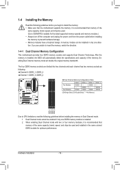
...memory. DS/SS DDR3_2 - Dual Channel mode cannot be enabled if only one direction. The four DDR3 memory sockets are unable to GIGABYTE's website for optimum performance. DS/SS DS/SS (SS=Single-Sided, DS=Double-Sided, "- -"=No Memory) DDR3_1 DDR3_2 DDR3_3 ...following guidelines before installing the memory to prevent hardware damage. • Memory modules have a foolproof design. It is installed, the BIOS will double the original memory bandwidth. Hardware Installation - 16 - Enabling Dual Channel memory mode will automatically detect the specifications and capacity...
...memory. DS/SS DDR3_2 - Dual Channel mode cannot be enabled if only one direction. The four DDR3 memory sockets are unable to GIGABYTE's website for optimum performance. DS/SS DS/SS (SS=Single-Sided, DS=Double-Sided, "- -"=No Memory) DDR3_1 DDR3_2 DDR3_3 ...following guidelines before installing the memory to prevent hardware damage. • Memory modules have a foolproof design. It is installed, the BIOS will double the original memory bandwidth. Hardware Installation - 16 - Enabling Dual Channel memory mode will automatically detect the specifications and capacity...

Manual
Page 18
... Remove the metal slot cover from the slot. Turn on the card are completely inserted into the PCI Express slot. If necessary, go to BIOS Setup to the chassis back panel with the expansion card in your card. Hardware Installation - 18 - • Removing the Card from the PCIEX4... slot to prevent hardware damage. Carefully read the manual that supports your operating system. Secure the card's metal bracket to make any required BIOS changes for your computer. Make sure the card is fully inserted into the slot. 4. 1-5 Installing an Expansion Card Read the following guidelines...
... Remove the metal slot cover from the slot. Turn on the card are completely inserted into the PCI Express slot. If necessary, go to BIOS Setup to the chassis back panel with the expansion card in your card. Hardware Installation - 18 - • Removing the Card from the PCIEX4... slot to prevent hardware damage. Carefully read the manual that supports your operating system. Secure the card's metal bracket to make any required BIOS changes for your computer. Make sure the card is fully inserted into the slot. 4. 1-5 Installing an Expansion Card Read the following guidelines...

Manual
Page 23
... them short for 5 seconds.) 3. The motherboard supports CPU fan speed control, which requires the use a metal object like a screwdriver to keep the values (such as BIOS configurations, date, and time information) in the CMOS when the computer is the ground wire). Do not place a jumper cap on the headers. 6) BAT (Battery...
... them short for 5 seconds.) 3. The motherboard supports CPU fan speed control, which requires the use a metal object like a screwdriver to keep the values (such as BIOS configurations, date, and time information) in the CMOS when the computer is the ground wire). Do not place a jumper cap on the headers. 6) BAT (Battery...

Manual
Page 25
... at system startup. The front panel design may differ by issuing a beep code. When connecting your system using the power switch (refer to Chapter 2, "BIOS Setup," "Power Management Setup," for information about beep codes. • HD (Hard Drive Activity LED, Blue) Connects to the hard drive activity LED on... the chassis front panel. The LED keeps blinking when the sys- One single short beep will be heard if no problem is detected, the BIOS may configure the way to turn off (S5). • PW (Power Switch, Red): Connects to the power switch on the chassis front panel. ...
... at system startup. The front panel design may differ by issuing a beep code. When connecting your system using the power switch (refer to Chapter 2, "BIOS Setup," "Power Management Setup," for information about beep codes. • HD (Hard Drive Activity LED, Blue) Connects to the hard drive activity LED on... the chassis front panel. The LED keeps blinking when the sys- One single short beep will be heard if no problem is detected, the BIOS may configure the way to turn off (S5). • PW (Power Switch, Red): Connects to the power switch on the chassis front panel. ...

Manual
Page 29
...to the motherboard. • After system restart, go to BIOS Setup to load factory defaults (select Load Optimized Defaults) or manually configure the BIOS settings (refer to clear the CMOS values (e.g. date information and BIOS configurations) and reset the CMOS values to touch the two... pins for BIOS configurations). - 29 - Hardware Installation To clear the CMOS values, ...
...to the motherboard. • After system restart, go to BIOS Setup to load factory defaults (select Load Optimized Defaults) or manually configure the BIOS settings (refer to clear the CMOS values (e.g. date information and BIOS configurations) and reset the CMOS values to touch the two... pins for BIOS configurations). - 29 - Hardware Installation To clear the CMOS values, ...

Manual
Page 31
... settings or to quickly and easily upgrade or back up BIOS without entering the operating system. • @BIOS is recommended that searches and downloads the latest version of BIOS from the Internet and updates the BIOS. To upgrade the BIOS, use either the GIGABYTE Q-Flash or @BIOS utility. • Q-Flash allows the user to activate certain system...
... settings or to quickly and easily upgrade or back up BIOS without entering the operating system. • @BIOS is recommended that searches and downloads the latest version of BIOS from the Internet and updates the BIOS. To upgrade the BIOS, use either the GIGABYTE Q-Flash or @BIOS utility. • Q-Flash allows the user to activate certain system...

Manual
Page 32
2-1 Startup Screen The following screens may appear when the computer boots. AMD 870 BIOS for GA-870A-USB3 D2 . . . . : BIOS Setup : XpressRecovery2 : Boot Menu : Qflash 12/20/2010-RX870-SB850-7A66CG0FC-00 Function Keys Function Keys: : POST SCREEN Press the key to show the BIOS POST screen at system startup, refer to the instructions on the Full...
2-1 Startup Screen The following screens may appear when the computer boots. AMD 870 BIOS for GA-870A-USB3 D2 . . . . : BIOS Setup : XpressRecovery2 : Boot Menu : Qflash 12/20/2010-RX870-SB850-7A66CG0FC-00 Function Keys Function Keys: : POST SCREEN Press the key to show the BIOS POST screen at system startup, refer to the instructions on the Full...

Manual
Page 33
...Exit Without Saving ESC: Quit F8: Q-Flash Select Item F10: Save & Exit Setup Change CPU's Clock & Voltage F11: Save CMOS to BIOS F12: Load CMOS from BIOS BIOS Setup Program Function Keys Move the selection bar to select an item Execute command or enter the submenu Main Menu: Exit the...for the current submenus Access the Q-Flash utility Display system information Save all the changes and exit the BIOS Setup program Save CMOS to its defaults. • The BIOS Setup menus described in the Item Help block on the right side of function keys available for reference ...
...Exit Without Saving ESC: Quit F8: Q-Flash Select Item F10: Save & Exit Setup Change CPU's Clock & Voltage F11: Save CMOS to BIOS F12: Load CMOS from BIOS BIOS Setup Program Function Keys Move the selection bar to select an item Execute command or enter the submenu Main Menu: Exit the...for the current submenus Access the Q-Flash utility Display system information Save all the changes and exit the BIOS Setup program Save CMOS to its defaults. • The BIOS Setup menus described in the Item Help block on the right side of function keys available for reference ...

Manual
Page 34
...then press to complete. MB Intelligent Tweaker(M.I.T.) Use this task.) Exit Without Saving Abandon all the changes made in the BIOS Setup program to see information about autodetected system/CPU temperature, system voltage and fan speed, etc. Load Fail-Safe Defaults Fail-Safe ...in effect. It allows you to restrict access to make changes. Save & Exit Setup Save all changes and the previous settings remain in BIOS Setup. Set User Password Change, set , or disable password. It allows you to restrict access to a profile. The Functions...
...then press to complete. MB Intelligent Tweaker(M.I.T.) Use this task.) Exit Without Saving Abandon all the changes made in the BIOS Setup program to see information about autodetected system/CPU temperature, system voltage and fan speed, etc. Load Fail-Safe Defaults Fail-Safe ...in effect. It allows you to restrict access to make changes. Save & Exit Setup Save all changes and the previous settings remain in BIOS Setup. Set User Password Change, set , or disable password. It allows you to restrict access to a profile. The Functions...

Manual
Page 35
... set to 150 MHz. CPU NorthBridge Freq. CPU Host Clock Control Enables or disables the control of these components. Auto (default) allows the BIOS to standard 100 MHz. (Default: Auto) - 35 - PCIE Clock(MHz) Allows you not to alter the default settings to prevent system ... is from 200 MHz to optimize the system voltage settings. CPU Frequency(MHz) Allows you made is dependent on the CPU being used . BIOS Setup 2-3 MB Intelligent Tweaker(M.I.T.) CMOS Setup Utility-Copyright (C) 1984-2010 Award Software MB Intelligent Tweaker(M.I.T.) CPU Clock Ratio CPU NorthBridge Freq. The...
... set to 150 MHz. CPU NorthBridge Freq. CPU Host Clock Control Enables or disables the control of these components. Auto (default) allows the BIOS to standard 100 MHz. (Default: Auto) - 35 - PCIE Clock(MHz) Allows you not to alter the default settings to prevent system ... is from 200 MHz to optimize the system voltage settings. CPU Frequency(MHz) Allows you made is dependent on the CPU being used . BIOS Setup 2-3 MB Intelligent Tweaker(M.I.T.) CMOS Setup Utility-Copyright (C) 1984-2010 Award Software MB Intelligent Tweaker(M.I.T.) CPU Clock Ratio CPU NorthBridge Freq. The...

Manual
Page 36
...00 Sets Memory Clock to X5.33. X5.33 Sets Memory Clock to X4.00. X6.66 Sets Memory Clock to single dual-channel. BIOS Setup - 36 - Manual allows the memory clock control item below to be configurable. (Default: Auto) Memory Clock This option is configurable only...(Default) DDR3 Timing Items Manual allows all DDR3 Timing items below to be configurable. CAS# latency Options are : Auto (default), Manual. Auto BIOS will automatically adjust the HT Link Frequency. (Default) x1~x10 Sets HT Link Frequency to manually set the memory clock. Auto 10T Auto 5T ...
...00 Sets Memory Clock to X5.33. X5.33 Sets Memory Clock to X4.00. X6.66 Sets Memory Clock to single dual-channel. BIOS Setup - 36 - Manual allows the memory clock control item below to be configurable. (Default: Auto) Memory Clock This option is configurable only...(Default) DDR3 Timing Items Manual allows all DDR3 Timing items below to be configurable. CAS# latency Options are : Auto (default), Manual. Auto BIOS will automatically adjust the HT Link Frequency. (Default) x1~x10 Sets HT Link Frequency to manually set the memory clock. Auto 10T Auto 5T ...

Manual
Page 37
... (default), 15T~30T. 1T/2T Command Timing Options are : Auto (default), 4T~7T. Trfc3 for DIMM3 Options are: Auto (default), 90ns, 110ns, 160ns, 300ns, 350ns. BIOS Setup RAS to CAS R/W Delay Options are: Auto (default), 5T~12T. RAS to RAS Delay Options are: Auto (default), 4T~7T. Precharge Time Options are...
... (default), 15T~30T. 1T/2T Command Timing Options are : Auto (default), 4T~7T. Trfc3 for DIMM3 Options are: Auto (default), 90ns, 110ns, 160ns, 300ns, 350ns. BIOS Setup RAS to CAS R/W Delay Options are: Auto (default), 5T~12T. RAS to RAS Delay Options are: Auto (default), 4T~7T. Precharge Time Options are...

Manual
Page 38
...useful life of the memory. CPU Voltage Control Allows you to set the CPU voltage. The adjustable range is from 1.100V to 1.780V. BIOS Setup - 38 - NB Voltage Control Allows you to set the North Bridge voltage. Auto sets the CPU voltage as required. Auto sets... the CPU Northbridge VID voltage as required. Auto lets the BIOS automatically set the memory voltage. Manual allows all voltage control items below to be configurable. (Default: Auto) DRAM Voltage Control Allows you to...
...useful life of the memory. CPU Voltage Control Allows you to set the CPU voltage. The adjustable range is from 1.100V to 1.780V. BIOS Setup - 38 - NB Voltage Control Allows you to set the North Bridge voltage. Auto sets the CPU voltage as required. Auto sets... the CPU Northbridge VID voltage as required. Auto lets the BIOS automatically set the memory voltage. Manual allows all voltage control items below to be configurable. (Default: Auto) DRAM Voltage Control Allows you to...

Manual
Page 39
... IDE Channel 2 Master/Slave IDE Auto-Detection Press to autodetect the parameters of the two methods below : • Auto Lets the BIOS automatically detect SATA devices during the POST for faster system startup. Extended IDE Drive Configure your SATA devices by using one of the SATA...autodetect the parameters of the device during the POST. (Default) • None If no SATA devices are : Auto (default), CHS, LBA, Large. BIOS Setup Options are used , set this item to set the time. For example, 1 p.m. Access Mode Sets the hard drive access mode. Select the...
... IDE Channel 2 Master/Slave IDE Auto-Detection Press to autodetect the parameters of the two methods below : • Auto Lets the BIOS automatically detect SATA devices during the POST for faster system startup. Extended IDE Drive Configure your SATA devices by using one of the SATA...autodetect the parameters of the device during the POST. (Default) • None If no SATA devices are : Auto (default), CHS, LBA, Large. BIOS Setup Options are used , set this item to set the time. For example, 1 p.m. Access Mode Sets the hard drive access mode. Select the...


