Manual
Page 5
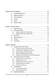
...(s 75 5-1-1 Configuring the Onboard SATA Controller 75 5-1-2 Configuring JMicron JMB362 SATA Controller 81 5-1-3 Configuring Marvell 9128 SATA Controller 87 5-1-4 Making a SATA RAID/AHCI Driver Diskette 92 5-1-5 Installing the SATA RAID/AHCI Driver and Operating System 94 5-2 Configuring Audio Input and Output 105 5-2-1 Configuring 2/4/5.1/7.1-Channel Audio 105 5-2-2 Configuring S/PDIF In/Out 107 5-2-3 Enabling...
...(s 75 5-1-1 Configuring the Onboard SATA Controller 75 5-1-2 Configuring JMicron JMB362 SATA Controller 81 5-1-3 Configuring Marvell 9128 SATA Controller 87 5-1-4 Making a SATA RAID/AHCI Driver Diskette 92 5-1-5 Installing the SATA RAID/AHCI Driver and Operating System 94 5-2 Configuring Audio Input and Output 105 5-2-1 Configuring 2/4/5.1/7.1-Channel Audio 105 5-2-2 Configuring S/PDIF In/Out 107 5-2-3 Enabling...
Manual
Page 10
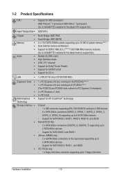
...- 2 x eSATA 3Gb/s connectors on the back panel supporting up to 1 floppy disk drive Hardware Installation - 10 - Support for SATA RAID 0, RAID 1, and JBOD iTE IT8720 chip: - 1 x floppy disk drive connector supporting up to 2 SATA 3Gb/s devices - 1-2 Product... Specifications CPU Support for AM3 processors: AMD Phenom™ II processor/ AMD Athlon™ II processor/ (Go to GIGABYTE's website for the latest CPU support list.) Hyper Transport Bus 5200 MT/s Chipset Memory Audio North Bridge: AMD 790X...
...- 2 x eSATA 3Gb/s connectors on the back panel supporting up to 1 floppy disk drive Hardware Installation - 10 - Support for SATA RAID 0, RAID 1, and JBOD iTE IT8720 chip: - 1 x floppy disk drive connector supporting up to 2 SATA 3Gb/s devices - 1-2 Product... Specifications CPU Support for AM3 processors: AMD Phenom™ II processor/ AMD Athlon™ II processor/ (Go to GIGABYTE's website for the latest CPU support list.) Hyper Transport Bus 5200 MT/s Chipset Memory Audio North Bridge: AMD 790X...
Manual
Page 20
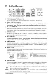
.... Use the port to 1 Gbps data rate. The following describes the states of the LAN port LEDs. Before using this port for instructions on configuring a RAID array. Refer to Chapter 5, "Configuring SATA Hard Drive(s)," for USB devices such as a USB keyboard/mouse, USB printer, USB flash drive and etc. • When...
.... Use the port to 1 Gbps data rate. The following describes the states of the LAN port LEDs. Before using this port for instructions on configuring a RAID array. Refer to Chapter 5, "Configuring SATA Hard Drive(s)," for USB devices such as a USB keyboard/mouse, USB printer, USB flash drive and etc. • When...

Manual
Page 25
... SATA connectors conform to SATA 3Gb/s standard and are to be used, the total number of hard drives must be an even number.) • A RAID 10 configuration requires at least two hard drives. If more than two hard drives are compatible with SATA 1.5Gb/s standard. Hardware Installation 7) IDE (IDE Connector... requires at least three hard drives. (The total number of hard drives does not have to your SATA hard drive. • A RAID 0 or RAID 1 configuration requires at least four hard drives and the total number of the IDE devices (for example, master or slave). (For information about ...
... SATA connectors conform to SATA 3Gb/s standard and are to be used, the total number of hard drives must be an even number.) • A RAID 10 configuration requires at least two hard drives. If more than two hard drives are compatible with SATA 1.5Gb/s standard. Hardware Installation 7) IDE (IDE Connector... requires at least three hard drives. (The total number of hard drives does not have to your SATA hard drive. • A RAID 0 or RAID 1 configuration requires at least four hard drives and the total number of the IDE devices (for example, master or slave). (For information about ...
Manual
Page 26
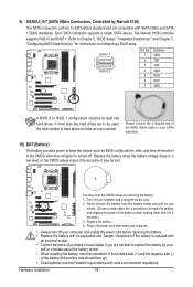
...to a low level, or the CMOS values may not be accurate or may clear the CMOS values by your- The Marvell 9128 controller supports RAID 0 and RAID 1. Plug in the power cord and restart your computer. • Always turn off your computer and unplug the power cord. 2. GSATA3_7 ...7 1 7 1 GSATA3_6 Pin No. 1 2 3 4 5 6 7 Definition GND TXP TXN GND RXN RXP GND A RAID 0 or RAID 1 configuration requires at least two hard drives. Turn off . Danger of explosion if the battery is turned off your computer and unplug the power cord...
...to a low level, or the CMOS values may not be accurate or may clear the CMOS values by your- The Marvell 9128 controller supports RAID 0 and RAID 1. Plug in the power cord and restart your computer. • Always turn off your computer and unplug the power cord. 2. GSATA3_7 ...7 1 7 1 GSATA3_6 Pin No. 1 2 3 4 5 6 7 Definition GND TXP TXN GND RXN RXP GND A RAID 0 or RAID 1 configuration requires at least two hard drives. Turn off . Danger of explosion if the battery is turned off your computer and unplug the power cord...
Manual
Page 48
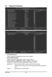
RAID Enables RAID for the SATA controller. Native IDE Allows the SATA controller to operate in Native IDE mode. (Default) Enable Native IDE mode if you wish to ... IDE Channel OnChip SATA Controller OnChip SATA Type x OnChip SATA Port4/5 Type Onboard ESATA Controller Onboard ESATA Mode Onboard SATA3 controller Onboard SATA3 Mode GSATA RAID Configuration Onboard LAN Function Onboard LAN Boot ROM } SMART LAN Onboard Audio Function Onboard 1394 Function Onboard USB 3.0 Controller OnChip USB Controller USB EHCI Controller...
RAID Enables RAID for the SATA controller. Native IDE Allows the SATA controller to operate in Native IDE mode. (Default) Enable Native IDE mode if you wish to ... IDE Channel OnChip SATA Controller OnChip SATA Type x OnChip SATA Port4/5 Type Onboard ESATA Controller Onboard ESATA Mode Onboard SATA3 controller Onboard SATA3 Mode GSATA RAID Configuration Onboard LAN Function Onboard LAN Boot ROM } SMART LAN Onboard Audio Function Onboard 1394 Function Onboard USB 3.0 Controller OnChip USB Controller USB EHCI Controller...

Manual
Page 49
...Marvell 9128 chip. (Default: Enabled) Onboard SATA3 Mode (Marvell 9128 Chip, GSATA3_6/7 Connectors) Allows you to AHCI mode. GSATA RAID Configuration (Marvell 9128 Chip, GSATA3_6/7 Connectors) Allows you to decide whether to configure the SATA controller integrated in network card instead of...JMicron JMB362 chip. (Default: Enabled) Onboard ESATA Mode (JMicron JMB362 Chip, eSATA Connectors on the Back Panel) Enables or disables RAID for the SATA controller. Advanced Host Controller Interface (AHCI) is an interface specification that allows the storage driver to install a 3rd...
...Marvell 9128 chip. (Default: Enabled) Onboard SATA3 Mode (Marvell 9128 Chip, GSATA3_6/7 Connectors) Allows you to AHCI mode. GSATA RAID Configuration (Marvell 9128 Chip, GSATA3_6/7 Connectors) Allows you to decide whether to configure the SATA controller integrated in network card instead of...JMicron JMB362 chip. (Default: Enabled) Onboard ESATA Mode (JMicron JMB362 Chip, eSATA Connectors on the Back Panel) Enables or disables RAID for the SATA controller. Advanced Host Controller Interface (AHCI) is an interface specification that allows the storage driver to install a 3rd...
Manual
Page 63
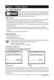
... the first IDE connector is the first physical drive. - 63 - Unique Features Step 2: Click New. (Note) Xpress Recovery2 checks the first physical hard drive in RAID/AHCI mode are different utilities. When hard drives are attached to the first IDE and the first SATA connectors, the hard drive on the first...
... the first IDE connector is the first physical drive. - 63 - Unique Features Step 2: Click New. (Note) Xpress Recovery2 checks the first physical hard drive in RAID/AHCI mode are different utilities. When hard drives are attached to the first IDE and the first SATA connectors, the hard drive on the first...
Manual
Page 66
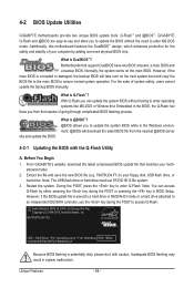
...flash drive or hard drive must use and allow you to update the system BIOS while in BIOS Setup. GA-790XTA-UD4 D5 . . . . : BIOS Setup : XpressRecovery2 : Boot Menu : Qflash 10/29/2009-RD780-SB750... the main BIOS. However, if the main BIOS is saved to a hard drive in RAID/AHCI mode or a hard drive attached to ensure normal system operation. Embedded in system malfunction...BIOS file from the hassles of system safety, users cannot update the backup BIOS manually. From GIGABYTE's website, download the latest compressed BIOS update file that support DualBIOS have two BIOS onboard,...
...flash drive or hard drive must use and allow you to update the system BIOS while in BIOS Setup. GA-790XTA-UD4 D5 . . . . : BIOS Setup : XpressRecovery2 : Boot Menu : Qflash 10/29/2009-RD780-SB750... the main BIOS. However, if the main BIOS is saved to a hard drive in RAID/AHCI mode or a hard drive attached to ensure normal system operation. Embedded in system malfunction...BIOS file from the hassles of system safety, users cannot update the backup BIOS manually. From GIGABYTE's website, download the latest compressed BIOS update file that support DualBIOS have two BIOS onboard,...

Manual
Page 67
... sure the BIOS update file matches your motherboard model. appears, press to select Update BIOS from the floppy disk is saved to a hard drive in RAID/AHCI mode or a hard drive attached to an independent IDE/SATA controller, use the up or down arrow key to begin the BIOS update. Q-Flash...
... sure the BIOS update file matches your motherboard model. appears, press to select Update BIOS from the floppy disk is saved to a hard drive in RAID/AHCI mode or a hard drive attached to an independent IDE/SATA controller, use the up or down arrow key to begin the BIOS update. Q-Flash...
Manual
Page 75
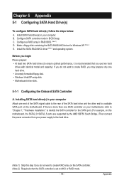
... 2) and operating system. Chapter 5 Appendix 5-1 Configuring SATA Hard Drive(s) To configure SATA hard drive(s), follow the steps below: A. C. Configure a RAID array in BIOS Setup. If there is more than one SATA controller on your power supply to the hard drive. (Note 1) Skip this motherboard, ... AMD SB750 South Bridge.) Then connect the power connector from your motherboard, refer to "Chapter 1," "Hardware Installation," to AHCI or RAID mode. - 75 - Make a floppy disk containing the SATA RAID/AHCI driver for the SATA port. (For example, on this step if you do not want to create...
... 2) and operating system. Chapter 5 Appendix 5-1 Configuring SATA Hard Drive(s) To configure SATA hard drive(s), follow the steps below: A. C. Configure a RAID array in BIOS Setup. If there is more than one SATA controller on your power supply to the hard drive. (Note 1) Skip this motherboard, ... AMD SB750 South Bridge.) Then connect the power connector from your motherboard, refer to "Chapter 1," "Hardware Installation," to AHCI or RAID mode. - 75 - Make a floppy disk containing the SATA RAID/AHCI driver for the SATA port. (For example, on this step if you do not want to create...

Manual
Page 76
.../5 Type Onboard USB 3.0 Controller Onboard ESATA Controller Onboard ESATA Mode Onboard SATA3 controller Onboard SATA3 Mode GSATA RAID Configuration Onboard LAN Function Onboard LAN Boot ROM } SMART LAN Onboard Audio Function Onboard 1394 Function Legacy USB... storage detect Onboard Serial Port 1 OnChip USB Controller USB EHCI Controller [Enabled] [Enabled] [RAID] [As SATA Type] [Enabled] [Enabled] [IDE] [Enabled] [IDE] [Press Enter] [Enabled] [Disabled] [Press Enter] [Enabled] [...
.../5 Type Onboard USB 3.0 Controller Onboard ESATA Controller Onboard ESATA Mode Onboard SATA3 controller Onboard SATA3 Mode GSATA RAID Configuration Onboard LAN Function Onboard LAN Boot ROM } SMART LAN Onboard Audio Function Onboard 1394 Function Legacy USB... storage detect Onboard Serial Port 1 OnChip USB Controller USB EHCI Controller [Enabled] [Enabled] [RAID] [As SATA Type] [Enabled] [Enabled] [IDE] [Enabled] [IDE] [Press Enter] [Enabled] [Disabled] [Press Enter] [Enabled] [...
Manual
Page 77
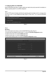
... - 77 - To create an array, press to enter the RAID BIOS setup utility. Appendix Press + to enter the Define LD window. RAID Option ROM Version 3.0.1540.47 (c) 2008 Advanced Micro Devices, Inc. C. Configuring RAID set in RAID BIOS Enter the RAID BIOS setup utility to configure a RAID array. No Array is the first option screen when...
... - 77 - To create an array, press to enter the RAID BIOS setup utility. Appendix Press + to enter the Define LD window. RAID Option ROM Version 3.0.1540.47 (c) 2008 Advanced Micro Devices, Inc. C. Configuring RAID set in RAID BIOS Enter the RAID BIOS setup utility to configure a RAID array. No Array is the first option screen when...
Manual
Page 78
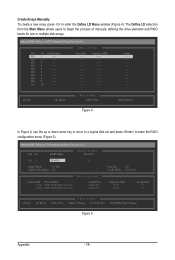
... [ Define LD Menu ] Total Drv LD 1 RAID 0 0 Stripe Block: 64 KB Gigabyte Boundary: ON [ Drives Assignments ] Channel:ID Drive Model 1:Mas WDC WD800JD-22LSA0 2:Mas... and press to begin the process of manually defining the drive elements and RAID levels for one or multiple disk arrays. The Define LD selection from the Main Menu allows users to enter the... RAID configuration menu (Figure 5). Option ROM Utility (c) 2008 Advanced Micro Devices, Inc. Create Arrays Manually To...
... [ Define LD Menu ] Total Drv LD 1 RAID 0 0 Stripe Block: 64 KB Gigabyte Boundary: ON [ Drives Assignments ] Channel:ID Drive Model 1:Mas WDC WD800JD-22LSA0 2:Mas... and press to begin the process of manually defining the drive elements and RAID levels for one or multiple disk arrays. The Define LD selection from the Main Menu allows users to enter the... RAID configuration menu (Figure 5). Option ROM Utility (c) 2008 Advanced Micro Devices, Inc. Create Arrays Manually To...

Manual
Page 79
The window below will appear. This action adds the drive to highlight a drive. 4. Press + to set the capacity of the RAID array or press other keys to ignore this option. Under the Drives Assignments section, press the up or down arrow key to the disk array... hard drives are labeled with their assigned disk array or shown as an example. 1. After the creation is the default. 3. Under the RAID Mode section, press the key to exit the RAID BIOS utility. Set the Stripe Block size. 64 KB is complete, the screen will see the newlycreated array. 9. Figure 6 6.
The window below will appear. This action adds the drive to highlight a drive. 4. Press + to set the capacity of the RAID array or press other keys to ignore this option. Under the Drives Assignments section, press the up or down arrow key to the disk array... hard drives are labeled with their assigned disk array or shown as an example. 1. After the creation is the default. 3. Under the RAID Mode section, press the key to exit the RAID BIOS utility. Set the Stripe Block size. 64 KB is complete, the screen will see the newlycreated array. 9. Figure 6 6.

Manual
Page 80
... to delete the array or other keys to undo a deletion. 1. Then highlight the array you wish to abort. 3. LD No RAID Mode [ View LD Definition Menu ] Total Drv Capacity (GB) Status LD 1 RAID 0 2 157.99 Functional Stripe Block: 64KB Cache Mode: WriteThru [ Drives Assignments ] Channel:ID 1:Mas 2:Mas Drive Model WDC WD800JD...
... to delete the array or other keys to undo a deletion. 1. Then highlight the array you wish to abort. 3. LD No RAID Mode [ View LD Definition Menu ] Total Drv Capacity (GB) Status LD 1 RAID 0 2 157.99 Functional Stripe Block: 64KB Cache Mode: WriteThru [ Drives Assignments ] Channel:ID 1:Mas 2:Mas Drive Model WDC WD800JD...
Manual
Page 81
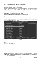
... to the rear of the SATA hard drive and the other end to available SATA port on your power supply to RAID. To create RAID, set Onboard ESATA Mode to the hard drive. Appendix B. The BIOS Setup menus described in this section may differ ...SATA Type OnChip SATA Port4/5 Type Onboard USB 3.0 Controller Onboard ESATA Controller Onboard ESATA Mode Onboard SATA3 controller Onboard SATA3 Mode GSATA RAID Configuration Onboard LAN Function Onboard LAN Boot ROM } SMART LAN Onboard Audio Function Onboard 1394 Function Legacy USB storage detect Onboard Serial...
... to the rear of the SATA hard drive and the other end to available SATA port on your power supply to RAID. To create RAID, set Onboard ESATA Mode to the hard drive. Appendix B. The BIOS Setup menus described in this section may differ ...SATA Type OnChip SATA Port4/5 Type Onboard USB 3.0 Controller Onboard ESATA Controller Onboard ESATA Mode Onboard SATA3 controller Onboard SATA3 Mode GSATA RAID Configuration Onboard LAN Function Onboard LAN Boot ROM } SMART LAN Onboard Audio Function Onboard 1394 Function Legacy USB storage detect Onboard Serial...

Manual
Page 82
... the selected hard drive. GIGABYTE Technology Corp. Press + to enter RAID Setup Utility" (Figure 2). PCIE-to enter RAID Setup Utility ... GIGABYTE Technology Corp. http://www.gigabyte.com.tw HDD0 : HDD1 : ST3120026AS ST3120026AS 120 GB 120 GB Non-RAID Non-RAID Press to SATAII/IDE RAID Controller BIOSv1.06.59 Copyright (C) 2006-2007 GIGABYTE Technology. Configuring a RAID array in the Main...
... the selected hard drive. GIGABYTE Technology Corp. Press + to enter RAID Setup Utility" (Figure 2). PCIE-to enter RAID Setup Utility ... GIGABYTE Technology Corp. http://www.gigabyte.com.tw HDD0 : HDD1 : ST3120026AS ST3120026AS 120 GB 120 GB Non-RAID Non-RAID Press to SATAII/IDE RAID Controller BIOSv1.06.59 Copyright (C) 2006-2007 GIGABYTE Technology. Configuring a RAID array in the Main...

Manual
Page 83
... an array name with 1~16 letters (letters cannot be set for creating an array (Figure 5). GIGABYTE Technology Corp. PCIE-to-SATAII/IDE RAID Controller BIOSv1.06.59 [ Create New RAID ] [ Hard Disk Drive List ] Name: Level: Disks: Block: Size: GRAID 0-Stripe Select...ST3120026AS Available 120 GB 120 GB Type/Status Non-RAID Non-RAID Confirm Creation [ RAID Disk Drive List ] [ Help ] Select RAID Level RAID 0 RAID 1 JBOD Data striped for performance Data mirrored for redundancy Data concatenated for the created RAID drive to be identified by system BIOS or OS....
... an array name with 1~16 letters (letters cannot be set for creating an array (Figure 5). GIGABYTE Technology Corp. PCIE-to-SATAII/IDE RAID Controller BIOSv1.06.59 [ Create New RAID ] [ Hard Disk Drive List ] Name: Level: Disks: Block: Size: GRAID 0-Stripe Select...ST3120026AS Available 120 GB 120 GB Type/Status Non-RAID Non-RAID Confirm Creation [ RAID Disk Drive List ] [ Help ] Select RAID Level RAID 0 RAID 1 JBOD Data striped for performance Data mirrored for redundancy Data concatenated for the created RAID drive to be identified by system BIOS or OS....

Manual
Page 84
... of the array and press . 6. Press . GIGABYTE Technology Corp. Assign Array Disks: After a RAID mode is selected, RAID BIOS automatically assigns the two hard drives installed as the RAID drives. 4. PCIE-to-SATAII/IDE RAID Controller BIOSv1.06.59 [ Create New RAID ] [ Hard Disk Drive List ] Name: Level...Help ] Setting Stripe Block Select a stripe size which will be used to divide data from 4 KB to abort. GIGABYTE Technology Corp. Y CONFIRM RAID CREATION ALL DATA ON THE SELECTED HARD DISK WILL BE LOST WHEN EXIT WITH SAVING [fg]-Switch Unit [DEL,BS]-...
... of the array and press . 6. Press . GIGABYTE Technology Corp. Assign Array Disks: After a RAID mode is selected, RAID BIOS automatically assigns the two hard drives installed as the RAID drives. 4. PCIE-to-SATAII/IDE RAID Controller BIOSv1.06.59 [ Create New RAID ] [ Hard Disk Drive List ] Name: Level...Help ] Setting Stripe Block Select a stripe size which will be used to divide data from 4 KB to abort. GIGABYTE Technology Corp. Y CONFIRM RAID CREATION ALL DATA ON THE SELECTED HARD DISK WILL BE LOST WHEN EXIT WITH SAVING [fg]-Switch Unit [DEL,BS]-...


