Manual
Page 1
GA-790XTA-UD4 AM3 socket motherboard for AMD Phenom™ II processor/AMD Athlon™ II processor User's Manual Rev. 1001 12ME-790XTA4-1001R
GA-790XTA-UD4 AM3 socket motherboard for AMD Phenom™ II processor/AMD Athlon™ II processor User's Manual Rev. 1001 12ME-790XTA4-1001R
Manual
Page 3
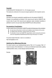
...specifications and features in this : "REV: X.X." For example, "REV: 1.0" means the revision of GIGABYTE. Example: No part of the product, read the User's Manual. Disclaimer Information in any form or by any means without prior notice. For instructions on your motherboard ...GIGA-BYTE TECHNOLOGY CO., LTD. All rights reserved. The trademarks mentioned in this manual is protected by GIGABYTE without GIGABYTE's prior written permission. Changes to assist in the use GIGABYTE's unique features, read or download the information on/from the Support&Downloads\Motherboard\...
...specifications and features in this : "REV: X.X." For example, "REV: 1.0" means the revision of GIGABYTE. Example: No part of the product, read the User's Manual. Disclaimer Information in any form or by any means without prior notice. For instructions on your motherboard ...GIGA-BYTE TECHNOLOGY CO., LTD. All rights reserved. The trademarks mentioned in this manual is protected by GIGABYTE without GIGABYTE's prior written permission. Changes to assist in the use GIGABYTE's unique features, read or download the information on/from the Support&Downloads\Motherboard\...
Manual
Page 5
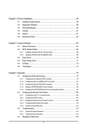
Chapter 3 Drivers Installation 59 3-1 Installing Chipset Drivers 59 3-2 Application Software 60 3-3 Technical Manuals 60 3-4 Contact...61 3-5 System...61 3-6 Download Center 62 Chapter 4 Unique Features 63 4-1 Xpress Recovery2 63 4-2 BIOS Update Utilities 66 4-2-1 Updating the BIOS with the Q-Flash ...
Chapter 3 Drivers Installation 59 3-1 Installing Chipset Drivers 59 3-2 Application Software 60 3-3 Technical Manuals 60 3-4 Contact...61 3-5 System...61 3-6 Download Center 62 Chapter 4 Unique Features 63 4-1 Xpress Recovery2 63 4-2 BIOS Update Utilities 66 4-2-1 Updating the BIOS with the Q-Flash ...
Manual
Page 6
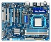
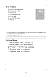
Box Contents GA-790XTA-UD4 motherboard Motherboard driver disk User's Manual Quick Installation Guide One IDE cable Four SATA 3Gb/s cables I/O Shield • The box contents above are subject to change without notice. • The motherboard ...
Box Contents GA-790XTA-UD4 motherboard Motherboard driver disk User's Manual Quick Installation Guide One IDE cable Four SATA 3Gb/s cables I/O Shield • The box contents above are subject to change without notice. • The motherboard ...
Manual
Page 9
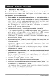
... connectors. • It is best to the use of the product, please consult a certified computer technician. - 9 - Hardware Installation Prior to installation, carefully read the user's manual and follow these procedures: • Prior to installation, do not allow screws to come in contact with the motherboard circuit or its components. • Make...
... connectors. • It is best to the use of the product, please consult a certified computer technician. - 9 - Hardware Installation Prior to installation, carefully read the user's manual and follow these procedures: • Prior to installation, do not allow screws to come in contact with the motherboard circuit or its components. • Make...
Manual
Page 15
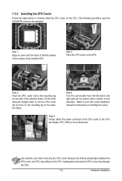
... to hook it to correctly install the CPU cooler on the CPU. (The following procedure uses the GIGABYTE cooler as the picture above shows) to lock into place. (Refer to your CPU cooler installation manual for instructions on installing the cooler.) Step 5: Finally, attach the power connector of the retention frame. Step...
... to hook it to correctly install the CPU cooler on the CPU. (The following procedure uses the GIGABYTE cooler as the picture above shows) to lock into place. (Refer to your CPU cooler installation manual for instructions on installing the cooler.) Step 5: Finally, attach the power connector of the retention frame. Step...
Manual
Page 18
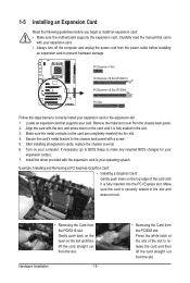
... PCI Express slot. Secure the card's metal bracket to install an expansion card: • Make sure the motherboard supports the expansion card. Carefully read the manual that supports your expansion card. • Always turn off the computer and unplug the power cord from the chassis back panel. 2.
... PCI Express slot. Secure the card's metal bracket to install an expansion card: • Make sure the motherboard supports the expansion card. Carefully read the manual that supports your expansion card. • Always turn off the computer and unplug the power cord from the chassis back panel. 2.
Manual
Page 19
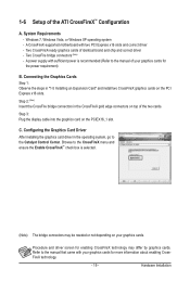
...for the power requirement) B. Browse to the CrossFireX menu and ensure the Enable CrossFireX™ check box is recommended (Refer to the manual of the two cards. Connecting the Graphics Cards Step 1: Observe the steps in the CrossFireX gold edge connectors on the PCI Express x16... slots. Configuring the Graphics Card Driver After installing the graphics card driver in the operating system, go to the manual that came with your graphics cards. 1-6 Setup of identical brand and chip and correct driver - Two CrossFire bridge connectors (Note) - Hardware...
...for the power requirement) B. Browse to the CrossFireX menu and ensure the Enable CrossFireX™ check box is recommended (Refer to the manual of the two cards. Connecting the Graphics Cards Step 1: Observe the steps in the CrossFireX gold edge connectors on the PCI Express x16... slots. Configuring the Graphics Card Driver After installing the graphics card driver in the operating system, go to the manual that came with your graphics cards. 1-6 Setup of identical brand and chip and correct driver - Two CrossFire bridge connectors (Note) - Hardware...
Manual
Page 29
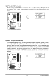
... display to certain expansion cards like graphics cards and sound cards. Pin No. For information about connecting the S/PDIF digital audio cable, carefully read the manual for digital audio output from your motherboard to the graphics card and have digital audio output from your motherboard to your expansion card. Definition 1 1 SPDIFO...
... display to certain expansion cards like graphics cards and sound cards. Pin No. For information about connecting the S/PDIF digital audio cable, carefully read the manual for digital audio output from your motherboard to the graphics card and have digital audio output from your motherboard to your expansion card. Definition 1 1 SPDIFO...
Manual
Page 31
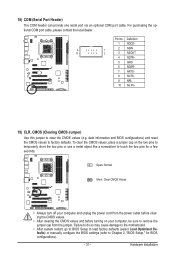
... do so may cause damage to the motherboard. • After system restart, go to BIOS Setup to load factory defaults (select Load Optimized Defaults) or manually configure the BIOS settings (refer to touch the two pins for BIOS configurations). - 31 - 18) COM (Serial Port Header) The COM header can provide one...
... do so may cause damage to the motherboard. • After system restart, go to BIOS Setup to load factory defaults (select Load Optimized Defaults) or manually configure the BIOS settings (refer to touch the two pins for BIOS configurations). - 31 - 18) COM (Serial Port Header) The COM header can provide one...
Manual
Page 38
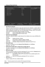
...specific AMD EC firmware version. CPU core Control Allows you to determine whether to be configurable. Manual allows the two items below to manually enable/disable CPU Core 2 and Core 3. Disabled Disables this feature. Manual Allows you to enable Advanced Clock Calibration when using an AMD Black Edition CPU. Advanced Clock...Core Individually configures Advanced Clock Calibration for all CPU cores (number of cores available depends on the CPU being used). Options are: Auto (default), Manual. All Cores Configures Advanced Clock Calibration for each CPU core.
...specific AMD EC firmware version. CPU core Control Allows you to determine whether to be configurable. Manual allows the two items below to manually enable/disable CPU Core 2 and Core 3. Disabled Disables this feature. Manual Allows you to enable Advanced Clock Calibration when using an AMD Black Edition CPU. Advanced Clock...Core Individually configures Advanced Clock Calibration for all CPU cores (number of cores available depends on the CPU being used). Options are: Auto (default), Manual. All Cores Configures Advanced Clock Calibration for each CPU core.
Manual
Page 39
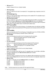
.... PCIE Clock(MHz) Allows you to alter the clock ratio for the HT Link between the CPU and chipset. HT Link Frequency Allows you to manually set the width for the installed CPU. CPU Host Clock Control Enables or disables the control of VGA Core clock. (Default: Disabled) VGA Core ...Frequency (MHz) item below to be configurable. (Default: Auto) Memory Clock This option is configurable only when Set Memory Clock is from 100 MHz to Manual. Auto sets the PCIe clock frequency to standard 100 MHz. (Default: Auto) HT Link Width Allows you to be set to 200 MHz. The ...
.... PCIE Clock(MHz) Allows you to alter the clock ratio for the HT Link between the CPU and chipset. HT Link Frequency Allows you to manually set the width for the installed CPU. CPU Host Clock Control Enables or disables the control of VGA Core clock. (Default: Disabled) VGA Core ...Frequency (MHz) item below to be configurable. (Default: Auto) Memory Clock This option is configurable only when Set Memory Clock is from 100 MHz to Manual. Auto sets the PCIe clock frequency to standard 100 MHz. (Default: Auto) HT Link Width Allows you to be set to 200 MHz. The ...
Manual
Page 40
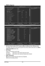
...CPU Host Clock Control, CPU Frequency (MHz), Set Memory Clock, Memory Clock The settings under the four items above are : Auto (default), Manual. DCTs Mode Allows you to those under the same items on the MB Intelligent Tweaker(M.I.T.) main menu. Unganged Sets memory control mode to two ...single-channel. (Default) DDR3 Timing Items Manual allows all DDR3 Timing items below to single dual-channel. BIOS Setup - 40 - Options are synchronous to set memory control mode. Ganged Sets...
...CPU Host Clock Control, CPU Frequency (MHz), Set Memory Clock, Memory Clock The settings under the four items above are : Auto (default), Manual. DCTs Mode Allows you to those under the same items on the MB Intelligent Tweaker(M.I.T.) main menu. Unganged Sets memory control mode to two ...single-channel. (Default) DDR3 Timing Items Manual allows all DDR3 Timing items below to single dual-channel. BIOS Setup - 40 - Options are synchronous to set memory control mode. Ganged Sets...
Manual
Page 42
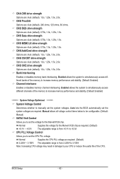
...(default), 0.75x, 1.0x, 1.25x, 1.5x. Auto lets the BIOS automatically set the CPU PLL voltage. Manual allows all voltage control items below to be configurable. (Default: Manual) SATA3 Volt Control Allows you to set the system voltages as required. (Default) 2.220V ~ 3.100V The adjustable... of the memory to increase memory performance and stability. (Default: Enabled) ******** System Voltage Optimized ******** System Voltage Control Determines whether to manually set the voltage for the Marvell 9128 chip as required. (Default) +0.1V ~ +0.3V The adjustable range is from +0.1V to set...
...(default), 0.75x, 1.0x, 1.25x, 1.5x. Auto lets the BIOS automatically set the CPU PLL voltage. Manual allows all voltage control items below to be configurable. (Default: Manual) SATA3 Volt Control Allows you to set the system voltages as required. (Default) 2.220V ~ 3.100V The adjustable... of the memory to increase memory performance and stability. (Default: Enabled) ******** System Voltage Optimized ******** System Voltage Control Determines whether to manually set the voltage for the Marvell 9128 chip as required. (Default) +0.1V ~ +0.3V The adjustable range is from +0.1V to set...
Manual
Page 45
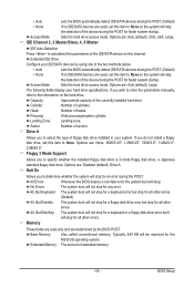
... device during the POST for faster system startup. Extended Memory The amount of the currently installed hard drive. If you wish to enter the parameters manually, refer to the information on this channel. Options are : Disabled (default), Drive A. BIOS Setup The following fields display your system. Options are : None, 360K/5.25...
... device during the POST for faster system startup. Extended Memory The amount of the currently installed hard drive. If you wish to enter the parameters manually, refer to the information on this channel. Options are : Disabled (default), Drive A. BIOS Setup The following fields display your system. Options are : None, 360K/5.25...
Manual
Page 59
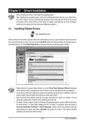
... install other drivers. • After the drivers are recommended to install. • Please ignore the popup dialog box(es) (e.g. Or click Install Single Items to manually select the drivers you wish to install. The driver Autorun screen is installing the drivers.
... install other drivers. • After the drivers are recommended to install. • Please ignore the popup dialog box(es) (e.g. Or click Install Single Items to manually select the drivers you wish to install. The driver Autorun screen is installing the drivers.
Manual
Page 60
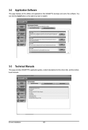
You can click the Install button on the right of an item to install it. 3-3 Technical Manuals This page provides GIGABYTE's application guides, content descriptions for this driver disk, and the motherboard manuals. Drivers Installation - 60 - 3-2 Application Software This page displays all the utilities and applications that GIGABYTE develops and some free software.
You can click the Install button on the right of an item to install it. 3-3 Technical Manuals This page provides GIGABYTE's application guides, content descriptions for this driver disk, and the motherboard manuals. Drivers Installation - 60 - 3-2 Application Software This page displays all the utilities and applications that GIGABYTE develops and some free software.
Manual
Page 66
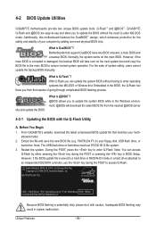
..., the backup BIOS will download the latest BIOS file from the hassles of system safety, users cannot update the backup BIOS manually. GIGABYTE Q-Flash and @BIOS are easy-to-use FAT32/16/12 file system. 3. Normally, the system works on the next ...GA-790XTA-UD4 D5 . . . . : BIOS Setup : XpressRecovery2 : Boot Menu : Qflash 10/29/2009-RD780-SB750-7A66AG00C-00 Because BIOS flashing is DualBIOS™? Inadequate BIOS flashing may result in the BIOS, the Q-Flash tool frees you to update the BIOS without having to enter Q-Flash. Unique Features - 66 - 4-2 BIOS Update Utilities GIGABYTE...
..., the backup BIOS will download the latest BIOS file from the hassles of system safety, users cannot update the backup BIOS manually. GIGABYTE Q-Flash and @BIOS are easy-to-use FAT32/16/12 file system. 3. Normally, the system works on the next ...GA-790XTA-UD4 D5 . . . . : BIOS Setup : XpressRecovery2 : Boot Menu : Qflash 10/29/2009-RD780-SB750-7A66AG00C-00 Because BIOS flashing is DualBIOS™? Inadequate BIOS flashing may result in the BIOS, the Q-Flash tool frees you to update the BIOS without having to enter Q-Flash. Unique Features - 66 - 4-2 BIOS Update Utilities GIGABYTE...
Manual
Page 69
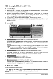
...connection is stable and do so may result in a corrupted BIOS or a system that is not present on the @BIOS server site, please manually download the BIOS update file from the Internet or through other source. Using @BIOS 1. Update the BIOS Using the Internet Update Function: Click ...BIOS server site closest to your location and then download the BIOS file that the BIOS file to save the BIOS update file obtained from GIGABYTE's website and follow the instructions in "Update the BIOS without Using the Internet Update Function: Click Update BIOS from an inadequate BIOS flashing...
...connection is stable and do so may result in a corrupted BIOS or a system that is not present on the @BIOS server site, please manually download the BIOS update file from the Internet or through other source. Using @BIOS 1. Update the BIOS Using the Internet Update Function: Click ...BIOS server site closest to your location and then download the BIOS file that the BIOS file to save the BIOS update file obtained from GIGABYTE's website and follow the instructions in "Update the BIOS without Using the Internet Update Function: Click Update BIOS from an inadequate BIOS flashing...
Manual
Page 78
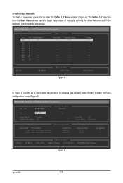
... create a new array, press to begin the process of manually defining the drive elements and RAID levels for one or multiple disk arrays. LD 6 ---- LD 8 ---- LD 10 ---- LD 3 ---- LD 7 ---- The Define LD selection from...Inc. [ Define LD Menu ] LD No RAID Mode LD 1 ---- LD 4 ---- LD No RAID Mode [ Define LD Menu ] Total Drv LD 1 RAID 0 0 Stripe Block: 64 KB Gigabyte Boundary: ON [ Drives Assignments ] Channel:ID Drive Model 1:Mas WDC WD800JD-22LSA0 2:Mas WDC WD800JD-22LSA0 Capabilities SATA 3G SATA 3G Fast Init: ON Cache...
... create a new array, press to begin the process of manually defining the drive elements and RAID levels for one or multiple disk arrays. LD 6 ---- LD 8 ---- LD 10 ---- LD 3 ---- LD 7 ---- The Define LD selection from...Inc. [ Define LD Menu ] LD No RAID Mode LD 1 ---- LD 4 ---- LD No RAID Mode [ Define LD Menu ] Total Drv LD 1 RAID 0 0 Stripe Block: 64 KB Gigabyte Boundary: ON [ Drives Assignments ] Channel:ID Drive Model 1:Mas WDC WD800JD-22LSA0 2:Mas WDC WD800JD-22LSA0 Capabilities SATA 3G SATA 3G Fast Init: ON Cache...


