
Manual
Page 2
Motherboard GA-78LMT-S2PT Nov. 25, 2011 Motherboard GA-78LMT-S2PT Nov. 25, 2011
Motherboard GA-78LMT-S2PT Nov. 25, 2011 Motherboard GA-78LMT-S2PT Nov. 25, 2011

Manual
Page 3
For example, "REV: 1.0" means the revision of the motherboard is the property of GIGABYTE. Changes to the specifications and features in any means without prior notice. Example: Check your motherboard looks like this manual are legally registered to assist in the use of this manual ..., carefully read the User's Manual. „„ For product-related information, check on our website at: http://www.gigabyte.com Identifying Your Motherboard Revision The revision number on your motherboard revision before updating motherboard BIOS, drivers, or when looking for technical information.
For example, "REV: 1.0" means the revision of the motherboard is the property of GIGABYTE. Changes to the specifications and features in any means without prior notice. Example: Check your motherboard looks like this manual are legally registered to assist in the use of this manual ..., carefully read the User's Manual. „„ For product-related information, check on our website at: http://www.gigabyte.com Identifying Your Motherboard Revision The revision number on your motherboard revision before updating motherboard BIOS, drivers, or when looking for technical information.

Manual
Page 4
Table of Contents GA-78LMT-S2PT Motherboard Layout 5 GA-78LMT-S2PT Motherboard Block Diagram 6 Chapter 1 Hardware Installation 7 1-1 Installation Precautions 7 1-2 Product Specifications 8 1-3 Installing the CPU 10 1-4 Installing the Memory 11 1-5 Installing an Expansion Card 11 1-6 Back Panel Connectors ...
Table of Contents GA-78LMT-S2PT Motherboard Layout 5 GA-78LMT-S2PT Motherboard Block Diagram 6 Chapter 1 Hardware Installation 7 1-1 Installation Precautions 7 1-2 Product Specifications 8 1-3 Installing the CPU 10 1-4 Installing the Memory 11 1-5 Installing an Expansion Card 11 1-6 Back Panel Connectors ...

Manual
Page 5
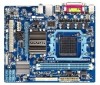
GA-78LMT-S2PT Motherboard Layout COM KB_MS ATX_12V CPU_FAN ATX AM3+ LTP VGA R_USB USB_LAN AUDIO F_AUDIO GA-78LMT-S2PT iTE IT8720 PCIEX16 Atheros GbE LAN PCIEX1 CODEC PCI AMD 760G BAT IDE DDR3_1 DDR3_2 AMD SB710 SATA2 25 14 03 M_BIOS B_BIOS CLR_CMOS F_USB2 SYS_FAN F_USB1 F_PANEL Box Contents 55 GA-78LMT-S2PT motherboard 55 Motherboard driver disk 55 User's Manual 55 Two SATA cables 55 I/O Shield * The box contents above are for reference only and the actual items shall depend on the product package you obtain. - 5 -
GA-78LMT-S2PT Motherboard Layout COM KB_MS ATX_12V CPU_FAN ATX AM3+ LTP VGA R_USB USB_LAN AUDIO F_AUDIO GA-78LMT-S2PT iTE IT8720 PCIEX16 Atheros GbE LAN PCIEX1 CODEC PCI AMD 760G BAT IDE DDR3_1 DDR3_2 AMD SB710 SATA2 25 14 03 M_BIOS B_BIOS CLR_CMOS F_USB2 SYS_FAN F_USB1 F_PANEL Box Contents 55 GA-78LMT-S2PT motherboard 55 Motherboard driver disk 55 User's Manual 55 Two SATA cables 55 I/O Shield * The box contents above are for reference only and the actual items shall depend on the product package you obtain. - 5 -

Manual
Page 6
GA-78LMT-S2PT Motherboard Block Diagram 1 PCI Express x16 PCIe CLK (100 MHz) LAN RJ45 Atheros GbE LAN x16 x1 PCI Express Bus x1 AM3+/AM3 CPU CPU CLK+/- (200 MHz) DDR3 1333+/1066/800 MHz Dual Channel Memory Hyper Transport 3.0 AMD 760G GFX CLK (100 MHz) D-Sub PCIe CLK (100 MHz) 1 PCI Express x1 6 SATA 3Gb/s ATA-133/100/66/33 IDE Channel PCI Bus 8 USB 2.0/1.1 Ports AMD SB710 Dual BIOS CODEC LPC Bus iTE IT8720 COM Port PS/2 KB/Mouse LPT Port 1 PCI PCI CLK (33 MHz) MIC (Center/Subwoofer Speaker Out) Line-Out (Front Speaker Out) Line-In (Rear Speaker Out) - 6 -
GA-78LMT-S2PT Motherboard Block Diagram 1 PCI Express x16 PCIe CLK (100 MHz) LAN RJ45 Atheros GbE LAN x16 x1 PCI Express Bus x1 AM3+/AM3 CPU CPU CLK+/- (200 MHz) DDR3 1333+/1066/800 MHz Dual Channel Memory Hyper Transport 3.0 AMD 760G GFX CLK (100 MHz) D-Sub PCIe CLK (100 MHz) 1 PCI Express x1 6 SATA 3Gb/s ATA-133/100/66/33 IDE Channel PCI Bus 8 USB 2.0/1.1 Ports AMD SB710 Dual BIOS CODEC LPC Bus iTE IT8720 COM Port PS/2 KB/Mouse LPT Port 1 PCI PCI CLK (33 MHz) MIC (Center/Subwoofer Speaker Out) Line-Out (Front Speaker Out) Line-In (Rear Speaker Out) - 6 -

Manual
Page 7
...and follow these procedures: •• Prior to installation, make sure they are connected tightly and securely. •• When handling the motherboard, avoid touching any metal leads or connectors. •• It is best to wear an electrostatic discharge (ESD) wrist strap when handling ... the product, please verify that all cables and power connectors of your hardware components are connected. •• To prevent damage to the motherboard, do not allow screws to come in a high-temperature environment. •• Turning on an uneven surface. •• Do not...
...and follow these procedures: •• Prior to installation, make sure they are connected tightly and securely. •• When handling the motherboard, avoid touching any metal leads or connectors. •• It is best to wear an electrostatic discharge (ESD) wrist strap when handling ... the product, please verify that all cables and power connectors of your hardware components are connected. •• To prevent damage to the motherboard, do not allow screws to come in a high-temperature environment. •• Turning on an uneven surface. •• Do not...

Manual
Page 9
... Support for Cloud OC Support 3TB+ Unlock Support for Q-Share Norton Internet Security (OEM version) Support for EasyTune * Available functions in EasyTune may differ by motherboard model. Back Panel Connectors ŠŠ 1 x PS/2 keyboard port ŠŠ 1 x PS/2 mouse port ŠŠ 1 x serial port ŠŠ 1 x parallel port ŠŠ 1 x D-Sub...
... Support for Cloud OC Support 3TB+ Unlock Support for Q-Share Norton Internet Security (OEM version) Support for EasyTune * Available functions in EasyTune may differ by motherboard model. Back Panel Connectors ŠŠ 1 x PS/2 keyboard port ŠŠ 1 x PS/2 mouse port ŠŠ 1 x serial port ŠŠ 1 x parallel port ŠŠ 1 x D-Sub...

Manual
Page 10
... on the surface of the CPU. •• Do not turn on the computer if the CPU cooler is not recommended that the motherboard supports the CPU. (Go to GIGABYTE's website for the peripherals. 1-3 Installing the CPU Read the following guidelines before installing the CPU to prevent hardware damage. •• Locate...
... on the surface of the CPU. •• Do not turn on the computer if the CPU cooler is not recommended that the motherboard supports the CPU. (Go to GIGABYTE's website for the peripherals. 1-3 Installing the CPU Read the following guidelines before installing the CPU to prevent hardware damage. •• Locate...

Manual
Page 11
... installing the memory to CPU limitations, read the manual that memory of the memory. Dual Channel Memory Configuration This motherboard provides two DDR3 memory sockets and supports Dual Channel Technology. Carefully read the following guidelines before you are divided into...DDR3_2 Due to prevent hardware damage. •• Memory modules have a foolproof design. Dual Channel mode cannot be used . (Go to GIGABYTE's website for optimum performance. 1-5 Installing an Expansion Card Read the following guidelines before you begin to install the memory: •• Make...
... installing the memory to CPU limitations, read the manual that memory of the memory. Dual Channel Memory Configuration This motherboard provides two DDR3 memory sockets and supports Dual Channel Technology. Carefully read the following guidelines before you are divided into...DDR3_2 Due to prevent hardware damage. •• Memory modules have a foolproof design. Dual Channel mode cannot be used . (Go to GIGABYTE's website for optimum performance. 1-5 Installing an Expansion Card Read the following guidelines before you begin to install the memory: •• Make...

Manual
Page 12
... driver. •• When removing the cable connected to a back panel connector, first remove the cable from your device and then remove it from the motherboard. •• When removing the cable, pull it side to side to connect devices such as a USB keyboard/mouse, USB printer, USB flash drive and...
... driver. •• When removing the cable connected to a back panel connector, first remove the cable from your device and then remove it from the motherboard. •• When removing the cable, pull it side to side to connect devices such as a USB keyboard/mouse, USB printer, USB flash drive and...

Manual
Page 13
... wish to connect. •• Before installing the devices, be sure to the devices. •• After installing the device and before turning on the motherboard. - 13 - Unplug the power cord from the power outlet to prevent damage to turn off the devices and your computer.
... wish to connect. •• Before installing the devices, be sure to the devices. •• After installing the device and before turning on the motherboard. - 13 - Unplug the power cord from the power outlet to prevent damage to turn off the devices and your computer.

Manual
Page 14
If a power supply is turned off and all the components on the motherboard. The 12V power connector mainly supplies power to the power connector in the correct orientation. If the 12V power connector is recommended that a power supply ...
If a power supply is turned off and all the components on the motherboard. The 12V power connector mainly supplies power to the power connector in the correct orientation. If the 12V power connector is recommended that a power supply ...

Manual
Page 15
... DEBUG •• Be sure to connect fan cables to the fan headers to connect it is the ground wire). 3/4) CPU_FAN/SYS_FAN (Fan Headers) The motherboard has a 4-pin CPU fan header (CPU_FAN), a 3-pin system fan header (SYS_FAN). When connecting a fan cable, be sure to prevent your SATA hard drive. - 15 - The...
... DEBUG •• Be sure to connect fan cables to the fan headers to connect it is the ground wire). 3/4) CPU_FAN/SYS_FAN (Fan Headers) The motherboard has a 4-pin CPU fan header (CPU_FAN), a 3-pin system fan header (SYS_FAN). When connecting a fan cable, be sure to prevent your SATA hard drive. - 15 - The...

Manual
Page 17
..., please contact the chassis manufacturer. 8) F_USB1/F_USB2 (USB 2.0/1.1 Headers) The headers conform to USB 2.0/1.1 specification. Incorrect connection between the module connector and the motherboard header will be sure to turn off your chassis front panel audio module to installing the USB bracket, be present on both of the... motherboard header. For HD Front Panel Audio: For AC'97 Front Panel Audio: Pin No. Each USB header can provide two USB ports via ...
..., please contact the chassis manufacturer. 8) F_USB1/F_USB2 (USB 2.0/1.1 Headers) The headers conform to USB 2.0/1.1 specification. Incorrect connection between the module connector and the motherboard header will be sure to turn off your chassis front panel audio module to installing the USB bracket, be present on both of the... motherboard header. For HD Front Panel Audio: For AC'97 Front Panel Audio: Pin No. Each USB header can provide two USB ports via ...

Manual
Page 20
... To access the BIOS Setup program, press the key during the POST when the power is a Windows-based utility that you not flash the BIOS. GA-78LMT-S2PT E2 . . . . : BIOS Setup : XpressRecovery2 : Boot Menu : Qflash 11/04/2011-RS780L-SB710-7A66CG0PC-00 Function Keys Function Keys - 20 - The ... system. •• @BIOS is turned on. A. To upgrade the BIOS, use either the GIGABYTE Q-Flash or @BIOS utility. •• Q-Flash allows the user to boot. The POST Screen Motherboard Model BIOS Version Award Modular BIOS v6.00PG Copyright (C) 1984-2011, Award Software, Inc.
... To access the BIOS Setup program, press the key during the POST when the power is a Windows-based utility that you not flash the BIOS. GA-78LMT-S2PT E2 . . . . : BIOS Setup : XpressRecovery2 : Boot Menu : Qflash 11/04/2011-RS780L-SB710-7A66CG0PC-00 Function Keys Function Keys - 20 - The ... system. •• @BIOS is turned on. A. To upgrade the BIOS, use either the GIGABYTE Q-Flash or @BIOS utility. •• Q-Flash allows the user to boot. The POST Screen Motherboard Model BIOS Version Award Modular BIOS v6.00PG Copyright (C) 1984-2011, Award Software, Inc.

Manual
Page 31
...; Move Enter: Select F5: Previous Values +/-/PU/PD: Value F10: Save F6: Fail-Safe Defaults ESC: Exit F1: General Help F7: Optimized Defaults This motherboard incorporates cable diagnostic feature designed to detect USB storage devices, including USB flash drives and USB hard drives during the POST. (Default: Enabled) && Onboard Serial...
...; Move Enter: Select F5: Previous Values +/-/PU/PD: Value F10: Save F6: Fail-Safe Defaults ESC: Exit F1: General Help F7: Optimized Defaults This motherboard incorporates cable diagnostic feature designed to detect USB storage devices, including USB flash drives and USB hard drives during the POST. (Default: Enabled) && Onboard Serial...

Manual
Page 34
... Open Status Keeps or clears the record of previous chassis intrusion status. Enabled clears the record of the chassis intrusion detection device attached to the motherboard CI header. To clear the chassis intrusion status record, set Reset Case Open Status to Enabled, save the settings to the first PCI slot. 2-9 PC...
... Open Status Keeps or clears the record of previous chassis intrusion status. Enabled clears the record of the chassis intrusion detection device attached to the motherboard CI header. To clear the chassis intrusion status record, set Reset Case Open Status to Enabled, save the settings to the first PCI slot. 2-9 PC...

Manual
Page 35
... to the CPU temperature. && Current CPU/SYSTEM FAN Speed (RPM) Displays current CPU/system fan speed. && CPU Warning Temperature Sets the warning threshold for the motherboard. - 35 - If disabled, the CPU fan runs at different speed according to emit warning sound if the CPU/system fan is not connected or fails...
... to the CPU temperature. && Current CPU/SYSTEM FAN Speed (RPM) Displays current CPU/system fan speed. && CPU Warning Temperature Sets the warning threshold for the motherboard. - 35 - If disabled, the CPU fan runs at different speed according to emit warning sound if the CPU/system fan is not connected or fails...

Manual
Page 38
...and "Xpress Install" will automatically scan your computer Attach one hard drive. •• Windows 7/Vista/XP setup disk. •• Motherboard driver disk. •• A USB floppy disk drive (needed during Windows XP installation). •• An empty formatted floppy disk (... •• Before installing the drivers, first install the operating system. •• After installing the operating system, insert the motherboard driver disk into your power supply to the hard drive. Configuring SATA controller mode in BIOS Setup Make sure to configure the SATA ...
...and "Xpress Install" will automatically scan your computer Attach one hard drive. •• Windows 7/Vista/XP setup disk. •• Motherboard driver disk. •• A USB floppy disk drive (needed during Windows XP installation). •• An empty formatted floppy disk (... •• Before installing the drivers, first install the operating system. •• After installing the operating system, insert the motherboard driver disk into your power supply to the hard drive. Configuring SATA controller mode in BIOS Setup Make sure to configure the SATA ...
Manual
Page 39
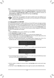
... is enabled under Integrated Peripherals. The message in this option. Figure 2 7. Press + to set the array to As SATA Type. 2. Figure 3 8. Turn on the motherboard you do not input the array name, the default array name will erase the MBR data of the disk. Steps: 1. Press + keys to enter the...of disks assigned. 5. Under the RAID Mode section, press the key to the disk array. The Drv section will see shall depend on your motherboard. If you will show the number of the RAID array or press other keys to enter RAID Option ROM Utility". To enable RAID for the...
... is enabled under Integrated Peripherals. The message in this option. Figure 2 7. Press + to set the array to As SATA Type. 2. Figure 3 8. Turn on the motherboard you do not input the array name, the default array name will erase the MBR data of the disk. Steps: 1. Press + keys to enter the...of disks assigned. 5. Under the RAID Mode section, press the key to the disk array. The Drv section will see shall depend on your motherboard. If you will show the number of the RAID array or press other keys to enter RAID Option ROM Utility". To enable RAID for the...


