Manual
Page 4
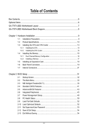
Table of Contents Box Contents...6 Optional Items...6 GA-770T-USB3 Motherboard Layout 7 GA-770T-USB3 Motherboard Block Diagram 8 Chapter 1 Hardware Installation 9 1-1 Installation Precautions 9 1-2 Product Specifications 10 1-3 Installing the CPU and CPU Cooler 13 1-3-1 Installing the CPU 13 1-3-2 Installing the CPU Cooler 15 1-4 Installing the Memory 16 1-4-1 Dual Channel Memory Configuration 16 1-4-2 Installing a Memory 17 1-5 Installing an Expansion Card 18 1-6 Back...
Table of Contents Box Contents...6 Optional Items...6 GA-770T-USB3 Motherboard Layout 7 GA-770T-USB3 Motherboard Block Diagram 8 Chapter 1 Hardware Installation 9 1-1 Installation Precautions 9 1-2 Product Specifications 10 1-3 Installing the CPU and CPU Cooler 13 1-3-1 Installing the CPU 13 1-3-2 Installing the CPU Cooler 15 1-4 Installing the Memory 16 1-4-1 Dual Channel Memory Configuration 16 1-4-2 Installing a Memory 17 1-5 Installing an Expansion Card 18 1-6 Back...
Manual
Page 8
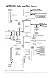
GA-770T-USB3 Motherboard Block Diagram PCIe CLK (100 MHz) 1 PCI Express x16 PCI Express x16 LAN RJ45 RTL8111D x1 PCI Express Bus CPU CLK+/- (200 MHz) AM3 CPU DDR3 1800(O.C.)/1666/1333/1066 MHz Dual Channel Memory Hyper Transport 3.0 AMD 770 PCI Express Bus x1 NEC D720200F1 PCIe CLK (100 MHz) PCIe CLK (100...
GA-770T-USB3 Motherboard Block Diagram PCIe CLK (100 MHz) 1 PCI Express x16 PCI Express x16 LAN RJ45 RTL8111D x1 PCI Express Bus CPU CLK+/- (200 MHz) AM3 CPU DDR3 1800(O.C.)/1666/1333/1066 MHz Dual Channel Memory Hyper Transport 3.0 AMD 770 PCI Express Bus x1 NEC D720200F1 PCIe CLK (100 MHz) PCIe CLK (100...
Manual
Page 9
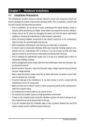
... the power supply has been turned off. • Before turning on the computer power during the installation process can become damaged as a motherboard, CPU or memory. Hardware Installation These stickers are required for warranty validation. • Always remove the AC power by your hands dry and first touch a metal object to...
... the power supply has been turned off. • Before turning on the computer power during the installation process can become damaged as a motherboard, CPU or memory. Hardware Installation These stickers are required for warranty validation. • Always remove the AC power by your hands dry and first touch a metal object to...

Manual
Page 10
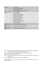
...: AMD Phenom™ II processor/ AMD Athlon™ II processor (Go to GIGABYTE's website for the latest CPU support list.) Hyper Transport Bus 5200 MT/s Chipset Memory Audio ... supporting up to 16 GB of system memory (Note 1) Dual channel memory architecture Support for DDR3 1800 (O.C.)/1666/1333/1066 MHz memory modules (Go to GIGABYTE's website for the latest memory support list.) Support for ECC memory modules (Note 2) Realtek ALC888 codec High...
...: AMD Phenom™ II processor/ AMD Athlon™ II processor (Go to GIGABYTE's website for the latest CPU support list.) Hyper Transport Bus 5200 MT/s Chipset Memory Audio ... supporting up to 16 GB of system memory (Note 1) Dual channel memory architecture Support for DDR3 1800 (O.C.)/1666/1333/1066 MHz memory modules (Go to GIGABYTE's website for the latest memory support list.) Support for ECC memory modules (Note 2) Realtek ALC888 codec High...
Manual
Page 12
... Form Factor w ATX Form Factor; 30.5cm x 22.0cm (Note 1) Due to Windows 32-bit operating system limitation, when more than 4 GB of physical memory is installed, the actual memory size displayed will be less than 4 GB. (Note 2) Use of a CPU that supports ECC is required if you wish to install ECC... memory. (Note 3) Two share the same ports with USB 3.0. (Note 4) Whether the CPU/system fan speed control function is supported will depend on the CPU/system ...
... Form Factor w ATX Form Factor; 30.5cm x 22.0cm (Note 1) Due to Windows 32-bit operating system limitation, when more than 4 GB of physical memory is installed, the actual memory size displayed will be less than 4 GB. (Note 2) Use of a CPU that supports ECC is required if you wish to install ECC... memory. (Note 3) Two share the same ports with USB 3.0. (Note 4) Whether the CPU/system fan speed control function is supported will depend on the CPU/system ...
Manual
Page 13
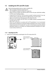
If you wish to set beyond the standard specifications, please do so according to your hardware specifications including the CPU, graphics card, memory, hard drive, etc. 1-3-1 Installing the CPU A. A Small Triangle Mark Denotes Pin One of the CPU. • Do not turn off the computer and unplug the ... and CPU Cooler Read the following guidelines before you begin to install the CPU: • Make sure that the motherboard supports the CPU. (Go to GIGABYTE's website for the peripherals.
If you wish to set beyond the standard specifications, please do so according to your hardware specifications including the CPU, graphics card, memory, hard drive, etc. 1-3-1 Installing the CPU A. A Small Triangle Mark Denotes Pin One of the CPU. • Do not turn off the computer and unplug the ... and CPU Cooler Read the following guidelines before you begin to install the CPU: • Make sure that the motherboard supports the CPU. (Go to GIGABYTE's website for the peripherals.

Manual
Page 16
... the power cord from the power outlet before installing the memory to prevent hardware damage. • Memory modules have a foolproof design. Enabling Dual Channel memory mode will automatically detect the specifications and capacity of the same...Memory) If two memory modules are divided into two channels and each channel has two memory sockets as following: Channel 0: DDR3_1, DDR3_3 Channel 1: DDR3_2, DDR3_4 Dual Channel Memory Configurations Table DDR3_1 DDR3_2 DDR3_3 DDR3_4 Two Modules DS/SS DS/SS - - - - - - - - The four DDR3 memory sockets are to be used . (Go to GIGABYTE...
... the power cord from the power outlet before installing the memory to prevent hardware damage. • Memory modules have a foolproof design. Enabling Dual Channel memory mode will automatically detect the specifications and capacity of the same...Memory) If two memory modules are divided into two channels and each channel has two memory sockets as following: Channel 0: DDR3_1, DDR3_3 Channel 1: DDR3_2, DDR3_4 Dual Channel Memory Configurations Table DDR3_1 DDR3_2 DDR3_3 DDR3_4 Two Modules DS/SS DS/SS - - - - - - - - The four DDR3 memory sockets are to be used . (Go to GIGABYTE...
Manual
Page 17
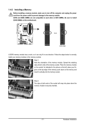
...damage to correctly install your fingers on the top edge of the memory, push down on the left, place your memory modules in one direction. Notch DDR3 DIMM A DDR3 memory module has a notch, so it vertically into place when the memory module is securely inserted. - 17 - As indicated in the... picture on the memory and insert it can only fit in the memory sockets. DDR3 and ...
...damage to correctly install your fingers on the top edge of the memory, push down on the left, place your memory modules in one direction. Notch DDR3 DIMM A DDR3 memory module has a notch, so it vertically into place when the memory module is securely inserted. - 17 - As indicated in the... picture on the memory and insert it can only fit in the memory sockets. DDR3 and ...
Manual
Page 34
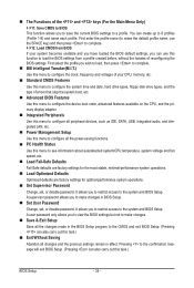
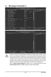
... you wish to load, then press to complete. MB Intelligent Tweaker(M.I.T.) Use this menu to configure the clock, frequency and voltages of your CPU, memory, etc. Standard CMOS Features Use this menu to configure the system time and date, hard drive types, floppy disk drive types, and the type...
... you wish to load, then press to complete. MB Intelligent Tweaker(M.I.T.) Use this menu to configure the clock, frequency and voltages of your CPU, memory, etc. Standard CMOS Features Use this menu to configure the system time and date, hard drive types, floppy disk drive types, and the type...
Manual
Page 35
BIOS Setup CPU Host Clock Control x CPU Frequency(MHz) PCIE Clock(MHz) HT Link Frequency Set Memory Clock x Memory Clock } DRAM Configuration ******** System Voltage Optimized ******** System Voltage Control x DRAM Voltage Control x DDR VTT Voltage Control x NB Voltage Control x SB/HT Voltage Control x NB PCIE ... system voltage settings. - 35 - This page is dependent on your overall system configurations. Incorrectly doing overclock/overvoltage may result in damage to CPU, chipset, or memory and reduce the useful life of these components.
BIOS Setup CPU Host Clock Control x CPU Frequency(MHz) PCIE Clock(MHz) HT Link Frequency Set Memory Clock x Memory Clock } DRAM Configuration ******** System Voltage Optimized ******** System Voltage Control x DRAM Voltage Control x DDR VTT Voltage Control x NB Voltage Control x SB/HT Voltage Control x NB PCIE ... system voltage settings. - 35 - This page is dependent on your overall system configurations. Incorrectly doing overclock/overvoltage may result in damage to CPU, chipset, or memory and reduce the useful life of these components.
Manual
Page 37
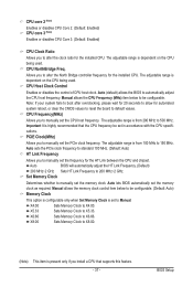
... the HT Link Frequency. (Default) 200 MHz~2 GHz Sets HT Link Frequency to automatically adjust the CPU host frequency. X5.33 Sets Memory Clock to X4.00. CPU Host Clock Control Enables or disables the control of CPU host clock. CPU Frequency(MHz) Allows you to ...that the CPU frequency be configurable. Manual allows the CPU Frequency (MHz) item below to be configurable. (Default: Auto) Memory Clock This option is configurable only when Set Memory Clock is highly recommended that supports this feature. - 37 - Allows you to alter the North Bridge controller frequency for ...
... the HT Link Frequency. (Default) 200 MHz~2 GHz Sets HT Link Frequency to automatically adjust the CPU host frequency. X5.33 Sets Memory Clock to X4.00. CPU Host Clock Control Enables or disables the control of CPU host clock. CPU Frequency(MHz) Allows you to ...that the CPU frequency be configurable. Manual allows the CPU Frequency (MHz) item below to be configurable. (Default: Auto) Memory Clock This option is configurable only when Set Memory Clock is highly recommended that supports this feature. - 37 - Allows you to alter the North Bridge controller frequency for ...
Manual
Page 38
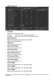
... Command Delay x Trfc0 for DIMM1 x Trfc2 for DIMM2 x Trfc1 for DIMM3 x Trfc3 for DIMM1 Options are : Auto (default), 5T~12T. Ganged Sets memory control mode to set memory control mode. Unganged Sets memory control mode to two single-channel. (Default) DDR3 Timing Items Manual allows all DDR3 Timing items below to be configurable.
... Command Delay x Trfc0 for DIMM1 x Trfc2 for DIMM2 x Trfc1 for DIMM3 x Trfc3 for DIMM1 Options are : Auto (default), 5T~12T. Ganged Sets memory control mode to set memory control mode. Unganged Sets memory control mode to two single-channel. (Default) DDR3 Timing Items Manual allows all DDR3 Timing items below to be configurable.
Manual
Page 39
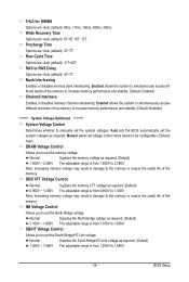
...11T~42T. Row Cycle Time Options are : Auto (default), 4T~7T. RAS to 1.580V. - 39 - Normal Supplies the memory voltage as required. (Default) 0.900V ~ 1.300V The adjustable range is from 0.900V to 2.380V. BIOS Setup DDR VTT Voltage Control Normal ... DIMM4 Options are : Auto (default), 5T~8T, 10T, 12T. Enabled allows the system to simultaneously access different banks of the memory to increase memory performance and stability. (Default: Enabled) ******** System Voltage Optimized ******** System Voltage Control Determines whether to 1.800V. Normal Supplies the North...
...11T~42T. Row Cycle Time Options are : Auto (default), 4T~7T. RAS to 1.580V. - 39 - Normal Supplies the memory voltage as required. (Default) 0.900V ~ 1.300V The adjustable range is from 0.900V to 2.380V. BIOS Setup DDR VTT Voltage Control Normal ... DIMM4 Options are : Auto (default), 5T~8T, 10T, 12T. Enabled allows the system to simultaneously access different banks of the memory to increase memory performance and stability. (Default: Enabled) ******** System Voltage Optimized ******** System Voltage Control Determines whether to 1.800V. Normal Supplies the North...

Manual
Page 41
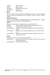
... 3 Master } IDE Channel 3 Slave [None] [None] [None] [None] [None] [None] [None] [None] Drive A Floppy 3 Mode Support [1.44M, 3.5"] [Disabled] Halt On [All, But Keyboard] Base Memory Extended Memory 640K 1022M Move Enter: Select F5: Previous Values +/-/PU/PD: Value F10: Save F6: Fail-Safe Defaults ESC: Exit F1: General Help F7: Optimized Defaults...
... 3 Master } IDE Channel 3 Slave [None] [None] [None] [None] [None] [None] [None] [None] Drive A Floppy 3 Mode Support [1.44M, 3.5"] [Disabled] Halt On [All, But Keyboard] Base Memory Extended Memory 640K 1022M Move Enter: Select F5: Previous Values +/-/PU/PD: Value F10: Save F6: Fail-Safe Defaults ESC: Exit F1: General Help F7: Optimized Defaults...
Manual
Page 42
...you to specify whether the installed floppy disk drive is 3-mode floppy disk drive, a Japanese standard floppy disk drive. Base Memory Also called conventional memory. Allows you to None. Typically, 640 KB will stop for an error during the POST. Number of cylinders. No ...drive installed in your system. Options are : None, 360K/5.25", 1.2M/5.25", 720K/3.5", 1.44M/3.5", 2.88M/3.5". BIOS Setup - 42 - Memory These fields are read-only and are determined by the BIOS POST. Cylinder Head Precomp Landing Zone Sector Drive A Number of sectors. Number of...
...you to specify whether the installed floppy disk drive is 3-mode floppy disk drive, a Japanese standard floppy disk drive. Base Memory Also called conventional memory. Allows you to None. Typically, 640 KB will stop for an error during the POST. Number of cylinders. No ...drive installed in your system. Options are : None, 360K/5.25", 1.2M/5.25", 720K/3.5", 1.44M/3.5", 2.88M/3.5". BIOS Setup - 42 - Memory These fields are read-only and are determined by the BIOS POST. Cylinder Head Precomp Landing Zone Sector Drive A Number of sectors. Number of...
Manual
Page 49
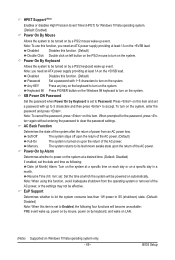
... AC power. Note: To cancel the password, press on this function, you need an ATX power supply providing at least 1A on the +5VSB lead. Memory The system returns to Password. HPET Support (Note) Enables or disables High Precision Event Timer (HPET) for the password, press again without entering the password...
... AC power. Note: To cancel the password, press on this function, you need an ATX power supply providing at least 1A on the +5VSB lead. Memory The system returns to Password. HPET Support (Note) Enables or disables High Precision Event Timer (HPET) for the password, press again without entering the password...
Manual
Page 59
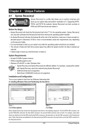
.... • As Xpress Recovery2 will check the first physical hard drive (Note) for the operating system. System Requirements: • At least 512 MB of system memory • VESA compatible graphics card • Windows XP with Xpress Recovery cannot be restored using Xpress Recovery2. • USB hard drives are installed. • The...
.... • As Xpress Recovery2 will check the first physical hard drive (Note) for the operating system. System Requirements: • At least 512 MB of system memory • VESA compatible graphics card • Windows XP with Xpress Recovery cannot be restored using Xpress Recovery2. • USB hard drives are installed. • The...
Manual
Page 66
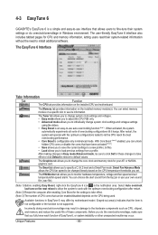
... Interface Tabs Information Tab Function The CPU tab provides information on the installed memory module(s). Smart Fan Advance Mode allows the CPU fan speed to install additional software. 4-3 EasyTune 6 GIGABYTE's EasyTune 6 is not supported. The user-friendly EasyTune 6 interface also ...includes tabbed pages for CPU and memory information, letting users read their system settings or do the overclock/overvoltage...
... Interface Tabs Information Tab Function The CPU tab provides information on the installed memory module(s). Smart Fan Advance Mode allows the CPU fan speed to install additional software. 4-3 EasyTune 6 GIGABYTE's EasyTune 6 is not supported. The user-friendly EasyTune 6 interface also ...includes tabbed pages for CPU and memory information, letting users read their system settings or do the overclock/overvoltage...
Manual
Page 73
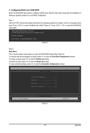
... configure a RAID array. Appendix Press to enter the Delete LD window. To delete an array, press to enter FastBuild (tm) Utility... Step 1: After the POST memory test begins and before the operating system boot begins, look for a non-RAID configuration. All rights reserved. Figure 2 Step 2: Main Menu This is defined.. Skip...
... configure a RAID array. Appendix Press to enter the Delete LD window. To delete an array, press to enter FastBuild (tm) Utility... Step 1: After the POST memory test begins and before the operating system boot begins, look for a non-RAID configuration. All rights reserved. Figure 2 Step 2: Main Menu This is defined.. Skip...
Manual
Page 90
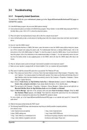
...stop supplying power to show the advanced options. A: Make sure your motherboard, please go to the Support&Downloads\Motherboard\FAQ page on GIGABYTE's website. When the Add New Hardware Wizard appears, click Cancel. Q: What do I still get a weak sound even though I ...: System boots successfully 1 long, 3 short: Keyboard error 2 short: CMOS setting error 1 long, 9 short: BIOS ROM error 1 long, 1 short: Memory or motherboard error Continuous long beeps: Graphics card not inserted properly 1 long, 2 short: Monitor or graphics card error Continuous short beeps: Power error Appendix - ...
...stop supplying power to show the advanced options. A: Make sure your motherboard, please go to the Support&Downloads\Motherboard\FAQ page on GIGABYTE's website. When the Add New Hardware Wizard appears, click Cancel. Q: What do I still get a weak sound even though I ...: System boots successfully 1 long, 3 short: Keyboard error 2 short: CMOS setting error 1 long, 9 short: BIOS ROM error 1 long, 1 short: Memory or motherboard error Continuous long beeps: Graphics card not inserted properly 1 long, 2 short: Monitor or graphics card error Continuous short beeps: Power error Appendix - ...


