Manual
Page 3
..., translated, transmitted, or published in the use GIGABYTE's unique features, read or download the information on/from the Support&Downloads\Motherboard\Technology Guide page on your motherboard revision before updating motherboard BIOS, drivers, or when looking for technical information. ...For instructions on how to the specifications and features in this : "REV: X.X." Example: For example, "REV: 1.0" means the revision of GIGABYTE. The trademarks mentioned in this...
..., translated, transmitted, or published in the use GIGABYTE's unique features, read or download the information on/from the Support&Downloads\Motherboard\Technology Guide page on your motherboard revision before updating motherboard BIOS, drivers, or when looking for technical information. ...For instructions on how to the specifications and features in this : "REV: X.X." Example: For example, "REV: 1.0" means the revision of GIGABYTE. The trademarks mentioned in this...
Manual
Page 4
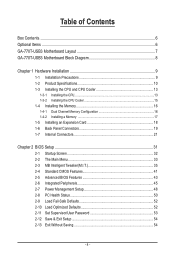
Table of Contents Box Contents...6 Optional Items...6 GA-770T-USB3 Motherboard Layout 7 GA-770T-USB3 Motherboard Block Diagram 8 Chapter 1 Hardware Installation 9 1-1 Installation Precautions 9 1-2 Product Specifications 10 1-3 Installing the CPU and CPU ... an Expansion Card 18 1-6 Back Panel Connectors 19 1-7 Internal Connectors 21 Chapter 2 BIOS Setup 31 2-1 Startup Screen 32 2-2 The Main Menu 33 2-3 MB Intelligent Tweaker(M.I.T 35 2-4 Standard CMOS Features 41 2-5 Advanced BIOS Features 43 2-6 Integrated Peripherals 45 2-7 Power Management Setup 48 2-8 PC Health Status ...
Table of Contents Box Contents...6 Optional Items...6 GA-770T-USB3 Motherboard Layout 7 GA-770T-USB3 Motherboard Block Diagram 8 Chapter 1 Hardware Installation 9 1-1 Installation Precautions 9 1-2 Product Specifications 10 1-3 Installing the CPU and CPU ... an Expansion Card 18 1-6 Back Panel Connectors 19 1-7 Internal Connectors 21 Chapter 2 BIOS Setup 31 2-1 Startup Screen 32 2-2 The Main Menu 33 2-3 MB Intelligent Tweaker(M.I.T 35 2-4 Standard CMOS Features 41 2-5 Advanced BIOS Features 43 2-6 Integrated Peripherals 45 2-7 Power Management Setup 48 2-8 PC Health Status ...

Manual
Page 5
... 56 3-3 Technical Manuals 56 3-4 Contact...57 3-5 System...57 3-6 Download Center 58 Chapter 4 Unique Features 59 4-1 Xpress Recovery2 59 4-2 BIOS Update Utilities 62 4-2-1 Updating the BIOS with the Q-Flash Utility 62 4-2-2 Updating the BIOS with the @BIOS Utility 65 4-3 EasyTune 6...66 4-4 Easy Energy Saver 67 4-5 Q-Share...69 4-6 SMART Recovery 70 Chapter 5 Appendix...71 5-1 Configuring SATA...
... 56 3-3 Technical Manuals 56 3-4 Contact...57 3-5 System...57 3-6 Download Center 58 Chapter 4 Unique Features 59 4-1 Xpress Recovery2 59 4-2 BIOS Update Utilities 62 4-2-1 Updating the BIOS with the Q-Flash Utility 62 4-2-2 Updating the BIOS with the @BIOS Utility 65 4-3 EasyTune 6...66 4-4 Easy Energy Saver 67 4-5 Q-Share...69 4-6 SMART Recovery 70 Chapter 5 Appendix...71 5-1 Configuring SATA...
Manual
Page 8
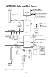
GA-770T-USB3 Motherboard Block Diagram PCIe CLK (100 MHz) 1 PCI Express x16 PCI Express x16 LAN RJ45 RTL8111D x1 PCI Express Bus CPU CLK+/- (200 MHz) AM3 ... Express Bus x1 NEC D720200F1 PCIe CLK (100 MHz) PCIe CLK (100 MHz) x1 x1 x1 x1 2 USB 3.0 12 USB 2.0/1.1(Note) 4 PCI Express x1 Dual BIOS PCI Bus TSB43AB23 AMD SB710 ATA-133/100/66/33 IDE Channel 6 SATA 3Gb/s CODEC LPC Bus IT8720 Floppy LPT Port COM Port 3 IEEE 1394a...
GA-770T-USB3 Motherboard Block Diagram PCIe CLK (100 MHz) 1 PCI Express x16 PCI Express x16 LAN RJ45 RTL8111D x1 PCI Express Bus CPU CLK+/- (200 MHz) AM3 ... Express Bus x1 NEC D720200F1 PCIe CLK (100 MHz) PCIe CLK (100 MHz) x1 x1 x1 x1 2 USB 3.0 12 USB 2.0/1.1(Note) 4 PCI Express x1 Dual BIOS PCI Bus TSB43AB23 AMD SB710 ATA-133/100/66/33 IDE Channel 6 SATA 3Gb/s CODEC LPC Bus IT8720 Floppy LPT Port COM Port 3 IEEE 1394a...
Manual
Page 12
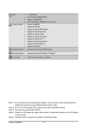
... Features w w w w w w w w w w Bundled Software w 2 x 8 Mbit flash Use of licensed AWARD BIOS Support for DualBIOS™ PnP 1.0a, DMI 2.0, SM BIOS 2.4, ACPI 1.0b Support for @BIOS Support for Q-Flash Support for Xpress BIOS Rescue Support for Download Center Support for Xpress Install Support for Xpress Recovery2 Support for EasyTune (Note 5) Support for Easy Energy Saver Support...
... Features w w w w w w w w w w Bundled Software w 2 x 8 Mbit flash Use of licensed AWARD BIOS Support for DualBIOS™ PnP 1.0a, DMI 2.0, SM BIOS 2.4, ACPI 1.0b Support for @BIOS Support for Q-Flash Support for Xpress BIOS Rescue Support for Download Center Support for Xpress Install Support for Xpress Recovery2 Support for EasyTune (Note 5) Support for Easy Energy Saver Support...

Manual
Page 16
...mode cannot be enabled if only one direction. When enabling Dual Channel mode with two or four memory modules, it is installed, the BIOS will double the original memory bandwidth. A memory module can be installed in Dual Channel mode. 1. The four DDR3 memory sockets are ... Channel Technology. After the memory is recommended that memory of the same capacity, brand, speed, and chips be used . (Go to GIGABYTE's website for optimum performance. Enabling Dual Channel memory mode will automatically detect the specifications and capacity of the memory. DDR3_1 DDR3_2 DDR3_3 DDR3_4...
...mode cannot be enabled if only one direction. When enabling Dual Channel mode with two or four memory modules, it is installed, the BIOS will double the original memory bandwidth. A memory module can be installed in Dual Channel mode. 1. The four DDR3 memory sockets are ... Channel Technology. After the memory is recommended that memory of the same capacity, brand, speed, and chips be used . (Go to GIGABYTE's website for optimum performance. Enabling Dual Channel memory mode will automatically detect the specifications and capacity of the memory. DDR3_1 DDR3_2 DDR3_3 DDR3_4...
Manual
Page 18
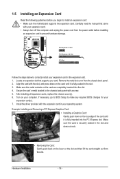
... and does not rock. • Removing the Card: Gently push back on the lever on your operating system. If necessary, go to BIOS Setup to prevent hardware damage. Make sure the card is securely seated in the slot. 3. After installing all expansion cards, replace the chassis... out from the chassis back panel. 2. 1-5 Installing an Expansion Card Read the following guidelines before installing an expansion card to make any required BIOS changes for your expansion card(s). 7. Align the card with the expansion card in the expansion slot. 1. Example: Installing and Removing a PCI ...
... and does not rock. • Removing the Card: Gently push back on the lever on your operating system. If necessary, go to BIOS Setup to prevent hardware damage. Make sure the card is securely seated in the slot. 3. After installing all expansion cards, replace the chassis... out from the chassis back panel. 2. 1-5 Installing an Expansion Card Read the following guidelines before installing an expansion card to make any required BIOS changes for your expansion card(s). 7. Align the card with the expansion card in the expansion slot. 1. Example: Installing and Removing a PCI ...
Manual
Page 25
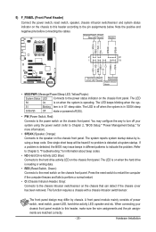
.../sensor on the chassis that can detect if the chassis cover has been removed. When connecting your system using the power switch (refer to Chapter 2, "BIOS Setup," "Power Management Setup," for information about beep codes. • HD (Hard Drive Activity LED, Blue) Connects to the hard drive activity LED on the... before connecting the cables. Message/Power/ Power Sleep LED Switch Speaker MSG+ MSG- The LED S0 On is on when the system is detected, the BIOS may issue beeps in S3/S4 sleep S3/S4/S5 Off state or powered off your chassis front panel module to this header according to...
.../sensor on the chassis that can detect if the chassis cover has been removed. When connecting your system using the power switch (refer to Chapter 2, "BIOS Setup," "Power Management Setup," for information about beep codes. • HD (Hard Drive Activity LED, Blue) Connects to the hard drive activity LED on the... before connecting the cables. Message/Power/ Power Sleep LED Switch Speaker MSG+ MSG- The LED S0 On is on when the system is detected, the BIOS may issue beeps in S3/S4 sleep S3/S4/S5 Off state or powered off your chassis front panel module to this header according to...
Manual
Page 30
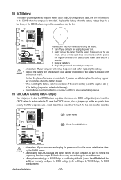
... environmental regulations. 19) CLR_CMOS (Clearing CMOS Jumper) Use this jumper to clear the CMOS values (e.g. Replace the battery. 4. date information and BIOS configurations) and reset the CMOS values to factory defaults. Open: Normal Short: Clear CMOS Values • Always turn off your computer, be ...from the battery holder and wait for 5 seconds.) 3. 18) BAT (Battery) The battery provides power to keep the values (such as BIOS configurations, date, and time information) in the CMOS when the computer is replaced with an incorrect model. • Contact the place of ...
... environmental regulations. 19) CLR_CMOS (Clearing CMOS Jumper) Use this jumper to clear the CMOS values (e.g. Replace the battery. 4. date information and BIOS configurations) and reset the CMOS values to factory defaults. Open: Normal Short: Clear CMOS Values • Always turn off your computer, be ...from the battery holder and wait for 5 seconds.) 3. 18) BAT (Battery) The battery provides power to keep the values (such as BIOS configurations, date, and time information) in the CMOS when the computer is replaced with an incorrect model. • Contact the place of ...
Manual
Page 31
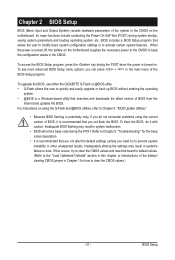
...," for how to quickly and easily upgrade or back up BIOS without entering the operating system. • @BIOS is recommended that searches and downloads the latest version of BIOS from the Internet and updates the BIOS. For instructions on the motherboard supplies the necessary power to ...in system's failure to activate certain system features. Chapter 2 BIOS Setup BIOS (Basic Input and Output System) records hardware parameters of the system in the CMOS on . BIOS Setup To upgrade the BIOS, use either the GIGABYTE Q-Flash or @BIOS utility. • Q-Flash allows the user to clear the ...
...," for how to quickly and easily upgrade or back up BIOS without entering the operating system. • @BIOS is recommended that searches and downloads the latest version of BIOS from the Internet and updates the BIOS. For instructions on the motherboard supplies the necessary power to ...in system's failure to activate certain system features. Chapter 2 BIOS Setup BIOS (Basic Input and Output System) records hardware parameters of the system in the CMOS on . BIOS Setup To upgrade the BIOS, use either the GIGABYTE Q-Flash or @BIOS utility. • Q-Flash allows the user to clear the ...
Manual
Page 32
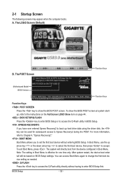
... The system will still be used for subsequent access to Xpress Recovery2 during the POST. Note: The setting in Boot Menu is effective for GA-770T-USB3 E7 . . . . : BIOS Setup : XpressRecovery2 : Boot Menu : Qflash 12/14/2009-RX780-SB710-7A66AG0WC-00 Function Keys Function Keys: : POST SCREEN Press the key...Boot Menu again to change the first boot device setting as needed. : Q-FLASH Press the key to accept. The POST Screen Award Modular BIOS v6.00PG, An Energy Star Ally Copyright (C) 1984-2009, Award Software, Inc. After system restart, the device boot order will directly boot...
... The system will still be used for subsequent access to Xpress Recovery2 during the POST. Note: The setting in Boot Menu is effective for GA-770T-USB3 E7 . . . . : BIOS Setup : XpressRecovery2 : Boot Menu : Qflash 12/14/2009-RX780-SB710-7A66AG0WC-00 Function Keys Function Keys: : POST SCREEN Press the key...Boot Menu again to change the first boot device setting as needed. : Q-FLASH Press the key to accept. The POST Screen Award Modular BIOS v6.00PG, An Energy Star Ally Copyright (C) 1984-2009, Award Software, Inc. After system restart, the device boot order will directly boot...
Manual
Page 33
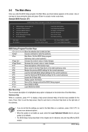
... Help for each item is in the Item Help block on the right side of function keys available for the menu. BIOS Setup Press to BIOS Load CMOS from BIOS BIOS Setup Program Function Keys Move the selection bar to select an item Execute command or enter the submenu Main Menu: Exit ...Submenu Help While in this chapter are for the current submenus Access the Q-Flash utility Display system information Save all the changes and exit the BIOS Setup program Save CMOS to exit the help screen (General Help) of the submenu. • If you do not find the settings you ...
... Help for each item is in the Item Help block on the right side of function keys available for the menu. BIOS Setup Press to BIOS Load CMOS from BIOS BIOS Setup Program Function Keys Move the selection bar to select an item Execute command or enter the submenu Main Menu: Exit ...Submenu Help While in this chapter are for the current submenus Access the Q-Flash utility Display system information Save all the changes and exit the BIOS Setup program Save CMOS to exit the help screen (General Help) of the submenu. • If you do not find the settings you ...
Manual
Page 34
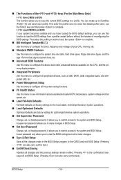
...time and date, hard drive types, floppy disk drive types, and the type of errors that stop the system boot, etc. Advanced BIOS Features Use this menu to configure the device boot order, advanced features available on the CPU, and the primary display adapter. Integrated .... MB Intelligent Tweaker(M.I.T.) Use this menu to configure the clock, frequency and voltages of your system becomes unstable and you have loaded the BIOS default settings, you to restrict access to a profile. It allows you can also carry out this menu to make changes. Save & ...
...time and date, hard drive types, floppy disk drive types, and the type of errors that stop the system boot, etc. Advanced BIOS Features Use this menu to configure the device boot order, advanced features available on the CPU, and the primary display adapter. Integrated .... MB Intelligent Tweaker(M.I.T.) Use this menu to configure the clock, frequency and voltages of your system becomes unstable and you have loaded the BIOS default settings, you to restrict access to a profile. It allows you can also carry out this menu to make changes. Save & ...
Manual
Page 35
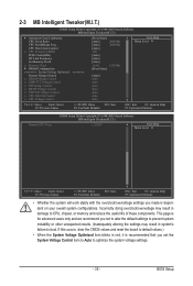
... is recommended that you set the System Voltage Control item to Auto to CPU, chipset, or memory and reduce the useful life of these components. BIOS Setup Incorrectly doing overclock/overvoltage may result in damage to optimize the system voltage settings. - 35 - 2-3 MB Intelligent Tweaker(M.I.T.) CMOS Setup Utility-Copyright (C) 1984-2009...
... is recommended that you set the System Voltage Control item to Auto to CPU, chipset, or memory and reduce the useful life of these components. BIOS Setup Incorrectly doing overclock/overvoltage may result in damage to optimize the system voltage settings. - 35 - 2-3 MB Intelligent Tweaker(M.I.T.) CMOS Setup Utility-Copyright (C) 1984-2009...
Manual
Page 36
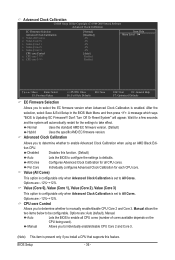
...: Fail-Safe Defaults ESC: Exit F1: General Help F7: Optimized Defaults EC Firmware Selection Allows you to All Cores. A message which says "BIOS Is Updating EC Firmware!!! Value (All Cores) This option is configurable only when Advanced Clock Calibration is set to defaults...Core 3. CPU core Control Allows you install a CPU that supports this function. (Default) Auto Lets the BIOS to configure the settings to All Cores. After the selection, select Save & Exit Setup in the BIOS Main Menu and then press . Don't Turn Off Or Reset System" will automatically restart for a few...
...: Fail-Safe Defaults ESC: Exit F1: General Help F7: Optimized Defaults EC Firmware Selection Allows you to All Cores. A message which says "BIOS Is Updating EC Firmware!!! Value (All Cores) This option is configurable only when Advanced Clock Calibration is set to defaults...Core 3. CPU core Control Allows you install a CPU that supports this function. (Default) Auto Lets the BIOS to configure the settings to All Cores. After the selection, select Save & Exit Setup in the BIOS Main Menu and then press . Don't Turn Off Or Reset System" will automatically restart for a few...
Manual
Page 37
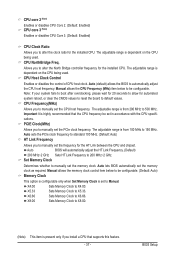
...alter the North Bridge controller frequency for the installed CPU. The adjustable range is dependent on the CPU being used . Auto (default) allows the BIOS to X5.33. Note: If your system fails to boot after overclocking, please wait for 20 seconds to Manual. X5.33 Sets Memory Clock ...MHz) item below to manually set the CPU host frequency. The adjustable range is from 100 MHz to manually set the PCIe clock frequency. BIOS Setup CPU Host Clock Control Enables or disables the control of CPU host clock. X4.00 Sets Memory Clock to default values. CPU NorthBridge Freq...
...alter the North Bridge controller frequency for the installed CPU. The adjustable range is dependent on the CPU being used . Auto (default) allows the BIOS to X5.33. Note: If your system fails to boot after overclocking, please wait for 20 seconds to Manual. X5.33 Sets Memory Clock ...MHz) item below to manually set the CPU host frequency. The adjustable range is from 100 MHz to manually set the PCIe clock frequency. BIOS Setup CPU Host Clock Control Enables or disables the control of CPU host clock. X4.00 Sets Memory Clock to default values. CPU NorthBridge Freq...
Manual
Page 38
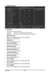
... for DIMM2 x Trfc1 for DIMM3 x Trfc3 for DIMM3 Options are: Auto (default), 90ns, 110ns, 160ns, 300ns, 350ns. TwTr Command Delay Options are : Auto (default), Manual. BIOS Setup - 38 - Auto 10T Auto 5T Auto 28T Auto 4T [Enabled] [Enabled] Auto 7T 7T 7T 30T -5T 90ns ---10T 5T 28T 4T Item Help...
... for DIMM2 x Trfc1 for DIMM3 x Trfc3 for DIMM3 Options are: Auto (default), 90ns, 110ns, 160ns, 300ns, 350ns. TwTr Command Delay Options are : Auto (default), Manual. BIOS Setup - 38 - Auto 10T Auto 5T Auto 28T Auto 4T [Enabled] [Enabled] Auto 7T 7T 7T 30T -5T 90ns ---10T 5T 28T 4T Item Help...
Manual
Page 39
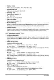
...control items below to be configurable. (Default: Auto) DRAM Voltage Control Allows you to RAS Delay Options are : Auto (default), 4T~7T. BIOS Setup Precharge Time Options are : Auto (default), 4T~7T. Bank Interleaving Enables or disables memory bank interleaving. Enabled allows the system to simultaneously...range is from 1.200V to manually set the system voltages. SB/HT Voltage Control Allows you to set the memory voltage. Auto lets the BIOS automatically set the South Bridge/HT-Link voltage. Write Recovery Time Options are : Auto (default), 90ns, 110ns, 160ns, 300ns, 350ns. ...
...control items below to be configurable. (Default: Auto) DRAM Voltage Control Allows you to RAS Delay Options are : Auto (default), 4T~7T. BIOS Setup Precharge Time Options are : Auto (default), 4T~7T. Bank Interleaving Enables or disables memory bank interleaving. Enabled allows the system to simultaneously...range is from 1.200V to manually set the system voltages. SB/HT Voltage Control Allows you to set the memory voltage. Auto lets the BIOS automatically set the South Bridge/HT-Link voltage. Write Recovery Time Options are : Auto (default), 90ns, 110ns, 160ns, 300ns, 350ns. ...

Manual
Page 40
... the CPU being installed. (Default: Normal) Note: Increasing CPU voltage may result in damage to your CPU or reduce the useful life of the CPU. BIOS Setup - 40 - CPU Voltage Control Allows you to set the North Bridge PCIe voltage. Auto sets the CPU voltage as required. NB PCIE Voltage Control...
... the CPU being installed. (Default: Normal) Note: Increasing CPU voltage may result in damage to your CPU or reduce the useful life of the CPU. BIOS Setup - 40 - CPU Voltage Control Allows you to set the North Bridge PCIe voltage. Auto sets the CPU voltage as required. NB PCIE Voltage Control...

Manual
Page 41
Extended IDE Drive Configure your IDE/SATA devices by using one of the two methods below : • Auto Lets the BIOS automatically detect IDE/SATA devices during the POST. (Default) • None If no IDE/SATA devices are used , set the date. Select the ...the hard drive access mode. The following fields display your IDE/SATA devices by using one of the two methods below : • Auto Lets the BIOS automatically detect IDE/SATA devices during the POST. (Default) • None If no IDE/SATA devices are used , set the time. Capacity Approximate ...
Extended IDE Drive Configure your IDE/SATA devices by using one of the two methods below : • Auto Lets the BIOS automatically detect IDE/SATA devices during the POST. (Default) • None If no IDE/SATA devices are used , set the date. Select the ...the hard drive access mode. The following fields display your IDE/SATA devices by using one of the two methods below : • Auto Lets the BIOS automatically detect IDE/SATA devices during the POST. (Default) • None If no IDE/SATA devices are used , set the time. Capacity Approximate ...


