Manual
Page 1
GA-770T-USB3 AM3 socket motherboard for AMD Phenom™ II processor/ AMD Athlon™ II processor User's Manual Rev. 1001 12ME-770TB3-1001R
GA-770T-USB3 AM3 socket motherboard for AMD Phenom™ II processor/ AMD Athlon™ II processor User's Manual Rev. 1001 12ME-770TB3-1001R
Manual
Page 3
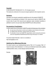
...1.0" means the revision of the motherboard is the property of this manual may be made by any form or by GIGABYTE without GIGABYTE's prior written permission. Check your motherboard looks like this manual may be reproduced, copied, translated, transmitted, or published in any...Documentation Classifications In order to their respective owners. The trademarks mentioned in the use GIGABYTE's unique features, read the User's Manual. Disclaimer Information in this product, GIGABYTE provides the following types of documentations: For quick set-up of this : "REV: X.X."
...1.0" means the revision of the motherboard is the property of this manual may be made by any form or by GIGABYTE without GIGABYTE's prior written permission. Check your motherboard looks like this manual may be reproduced, copied, translated, transmitted, or published in any...Documentation Classifications In order to their respective owners. The trademarks mentioned in the use GIGABYTE's unique features, read the User's Manual. Disclaimer Information in this product, GIGABYTE provides the following types of documentations: For quick set-up of this : "REV: X.X."

Manual
Page 5
Chapter 3 Drivers Installation 55 3-1 Installing Chipset Drivers 55 3-2 Application Software 56 3-3 Technical Manuals 56 3-4 Contact...57 3-5 System...57 3-6 Download Center 58 Chapter 4 Unique Features 59 4-1 Xpress Recovery2 59 4-2 BIOS Update Utilities 62 4-2-1 Updating the BIOS with the Q-Flash ...
Chapter 3 Drivers Installation 55 3-1 Installing Chipset Drivers 55 3-2 Application Software 56 3-3 Technical Manuals 56 3-4 Contact...57 3-5 System...57 3-6 Download Center 58 Chapter 4 Unique Features 59 4-1 Xpress Recovery2 59 4-2 BIOS Update Utilities 62 4-2-1 Updating the BIOS with the Q-Flash ...
Manual
Page 6
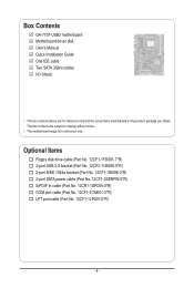
... In cable (Part No. 12CR1-1SPDIN-0*R) COM port cable (Part No. 12CF1-1CM001-3*R) LPT port cable (Part No. 12CF1-1LP001-0*R) - 6 - Box Contents GA-770T-USB3 motherboard Motherboard driver disk User's Manual Quick Installation Guide One IDE cable Two SATA 3Gb/s cables I/O Shield • The box contents above are subject to change without notice. •...
... In cable (Part No. 12CR1-1SPDIN-0*R) COM port cable (Part No. 12CF1-1CM001-3*R) LPT port cable (Part No. 12CF1-1LP001-0*R) - 6 - Box Contents GA-770T-USB3 motherboard Motherboard driver disk User's Manual Quick Installation Guide One IDE cable Two SATA 3Gb/s cables I/O Shield • The box contents above are subject to change without notice. •...
Manual
Page 9
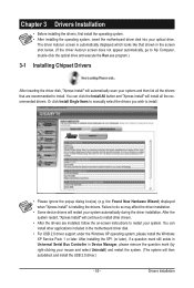
Prior to installation, carefully read the user's manual and follow these procedures: • Prior to installation, do not remove or break motherboard S/N (Serial Number) sticker or warranty sticker provided by unplugging the power ...
Prior to installation, carefully read the user's manual and follow these procedures: • Prior to installation, do not remove or break motherboard S/N (Serial Number) sticker or warranty sticker provided by unplugging the power ...
Manual
Page 15
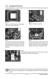
... cooler may adhere to correctly install the CPU cooler on the CPU. (The following procedure uses the GIGABYTE cooler as the picture above shows) to lock into place. (Refer to your CPU cooler installation manual for instructions on installing the cooler.) Step 5: Finally, attach the power connector of the installed CPU. 1-3-2 Installing...
... cooler may adhere to correctly install the CPU cooler on the CPU. (The following procedure uses the GIGABYTE cooler as the picture above shows) to lock into place. (Refer to your CPU cooler installation manual for instructions on installing the cooler.) Step 5: Finally, attach the power connector of the installed CPU. 1-3-2 Installing...
Manual
Page 18
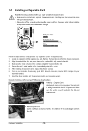
... the driver provided with the slot, and press down on the slot and then lift the card straight out from the slot. Carefully read the manual that supports your expansion card in the expansion slot. 1. If necessary, go to BIOS Setup to install an expansion card: • Make sure the motherboard...
... the driver provided with the slot, and press down on the slot and then lift the card straight out from the slot. Carefully read the manual that supports your expansion card in the expansion slot. 1. If necessary, go to BIOS Setup to install an expansion card: • Make sure the motherboard...

Manual
Page 27
... digital audio output from the HDMI display at the same time. Hardware Installation For information about connecting the S/PDIF digital audio cable, carefully read the manual for digital audio output from your expansion card. Pin No. Definition 1 Power 2 SPDIFI 1 3 GND 13) SPDIF_OUT (S/PDIF Out Header) This header supports digital S/PDIF Out...
... digital audio output from the HDMI display at the same time. Hardware Installation For information about connecting the S/PDIF digital audio cable, carefully read the manual for digital audio output from your expansion card. Pin No. Definition 1 Power 2 SPDIFI 1 3 GND 13) SPDIF_OUT (S/PDIF Out Header) This header supports digital S/PDIF Out...
Manual
Page 30
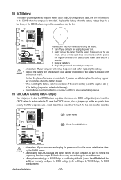
... do so may cause damage to the motherboard. • After system restart, go to BIOS Setup to load factory defaults (select Load Optimized Defaults) or manually configure the BIOS settings (refer to factory defaults. Open: Normal Short: Clear CMOS Values • Always turn off . You may be sure to remove the...
... do so may cause damage to the motherboard. • After system restart, go to BIOS Setup to load factory defaults (select Load Optimized Defaults) or manually configure the BIOS settings (refer to factory defaults. Open: Normal Short: Clear CMOS Values • Always turn off . You may be sure to remove the...
Manual
Page 36
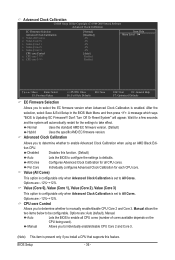
... is set to enable all CPU cores. All Cores Configures Advanced Clock Calibration for each CPU core. Options are : Auto (default), Manual. Manual allows the two items below to select the EC firmware version when Advanced Clock Calibration is present only if you install a CPU that... Selection Allows you to be configurable. Normal Uses the standard AMD EC firmware version. (Default) Hybrid Uses the specific AMD EC firmware version. Manual Allows you to determine whether to individually enable/disable CPU Core 2 and Core 3. (Note) This item is enabled. BIOS Setup - 36 ...
... is set to enable all CPU cores. All Cores Configures Advanced Clock Calibration for each CPU core. Options are : Auto (default), Manual. Manual allows the two items below to select the EC firmware version when Advanced Clock Calibration is present only if you install a CPU that... Selection Allows you to be configurable. Normal Uses the standard AMD EC firmware version. (Default) Hybrid Uses the specific AMD EC firmware version. Manual Allows you to determine whether to individually enable/disable CPU Core 2 and Core 3. (Note) This item is enabled. BIOS Setup - 36 ...
Manual
Page 37
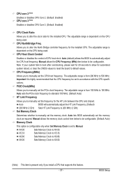
...you install a CPU that the CPU frequency be set in accordance with the CPU specifications. Auto lets BIOS automatically set the CPU host frequency. Manual allows the CPU Frequency (MHz) item below to 150 MHz. BIOS Setup The adjustable range is highly recommended that supports this feature. - 37 ...- Important It is dependent on the CPU being used . CPU Frequency(MHz) Allows you to manually set to manually set the memory clock as required. CPU Host Clock Control Enables or disables the control of CPU host clock. Auto sets the PCIe ...
...you install a CPU that the CPU frequency be set in accordance with the CPU specifications. Auto lets BIOS automatically set the CPU host frequency. Manual allows the CPU Frequency (MHz) item below to 150 MHz. BIOS Setup The adjustable range is highly recommended that supports this feature. - 37 ...- Important It is dependent on the CPU being used . CPU Frequency(MHz) Allows you to manually set to manually set the memory clock as required. CPU Host Clock Control Enables or disables the control of CPU host clock. Auto sets the PCIe ...
Manual
Page 38
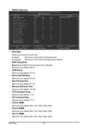
Options are : Auto (default), 5T~12T. Row Precharge Time Options are : Auto (default), Manual. RAS to CAS R/W Delay Options are : Auto (default), 4T~7T. TwTr Command Delay Options are : Auto (default), 5T~12T. Trfc1 for DIMM4 x Write Recovery...] SPD Auto 7T Auto 7T Auto 7T Auto 30T Auto -- Auto -- Unganged Sets memory control mode to two single-channel. (Default) DDR3 Timing Items Manual allows all DDR3 Timing items below to single dual-channel. BIOS Setup - 38 - DRAM Configuration CMOS Setup Utility-Copyright (C) 1984-2009 Award Software DRAM Configuration...
Options are : Auto (default), 5T~12T. Row Precharge Time Options are : Auto (default), Manual. RAS to CAS R/W Delay Options are : Auto (default), 4T~7T. TwTr Command Delay Options are : Auto (default), 5T~12T. Trfc1 for DIMM4 x Write Recovery...] SPD Auto 7T Auto 7T Auto 7T Auto 30T Auto -- Auto -- Unganged Sets memory control mode to two single-channel. (Default) DDR3 Timing Items Manual allows all DDR3 Timing items below to single dual-channel. BIOS Setup - 38 - DRAM Configuration CMOS Setup Utility-Copyright (C) 1984-2009 Award Software DRAM Configuration...
Manual
Page 39
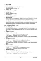
... voltage. Enabled allows the system to simultaneously access different banks of the memory NB Voltage Control Allows you to manually set the North Bridge voltage. Normal Supplies the North Bridge voltage as required. Manual allows all voltage control items below to be configurable. (Default: Auto) DRAM Voltage Control Allows you to 1.800V...
... voltage. Enabled allows the system to simultaneously access different banks of the memory NB Voltage Control Allows you to manually set the North Bridge voltage. Normal Supplies the North Bridge voltage as required. Manual allows all voltage control items below to be configurable. (Default: Auto) DRAM Voltage Control Allows you to 1.800V...

Manual
Page 41
...-Safe Defaults ESC: Exit F1: General Help F7: Optimized Defaults Date (mm:dd:yy) Sets the system date. If you wish to enter the parameters manually, refer to None so the system will skip the detection of the IDE/SATA device on the hard drive. Options are : Auto (default), Large. BIOS...
...-Safe Defaults ESC: Exit F1: General Help F7: Optimized Defaults Date (mm:dd:yy) Sets the system date. If you wish to enter the parameters manually, refer to None so the system will skip the detection of the IDE/SATA device on the hard drive. Options are : Auto (default), Large. BIOS...
Manual
Page 55
.... (The system will install all the recommended drivers. After the system restart, "Xpress Install" will restart your optical drive. Or click Install Single Items to manually select the drivers you wish to install other applications included in Device Manager, please remove the question mark (by right-clicking your system. You can...
.... (The system will install all the recommended drivers. After the system restart, "Xpress Install" will restart your optical drive. Or click Install Single Items to manually select the drivers you wish to install other applications included in Device Manager, please remove the question mark (by right-clicking your system. You can...
Manual
Page 56
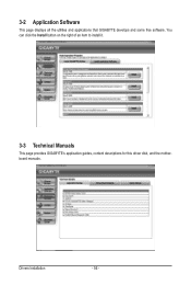
3-2 Application Software This page displays all the utilities and applications that GIGABYTE develops and some free software. Drivers Installation - 56 - You can click the Install button on the right of an item to install it. 3-3 Technical Manuals This page provides GIGABYTE's application guides, content descriptions for this driver disk, and the motherboard manuals.
3-2 Application Software This page displays all the utilities and applications that GIGABYTE develops and some free software. Drivers Installation - 56 - You can click the Install button on the right of an item to install it. 3-3 Technical Manuals This page provides GIGABYTE's application guides, content descriptions for this driver disk, and the motherboard manuals.
Manual
Page 62
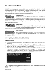
...and update the BIOS. AMD 770 BIOS for the safety and stability of system safety, users cannot update the backup BIOS manually. Motherboards that matches your USB flash drive or USB hard drive. What is DualBIOS™? What is Q-Flash™?...BIOS file (e.g. 770tusb3.f1) to enter Q-Flash. 4-2 BIOS Update Utilities GIGABYTE motherboards provide two unique BIOS update tools, Q-Flash™ and @BIOS™. Additionally, this motherboard features the DualBIOS™ design, which enhances protection for GA-770T-USB3 E7 . . . . : BIOS Setup : XpressRecovery2 : Boot Menu ...
...and update the BIOS. AMD 770 BIOS for the safety and stability of system safety, users cannot update the backup BIOS manually. Motherboards that matches your USB flash drive or USB hard drive. What is DualBIOS™? What is Q-Flash™?...BIOS file (e.g. 770tusb3.f1) to enter Q-Flash. 4-2 BIOS Update Utilities GIGABYTE motherboards provide two unique BIOS update tools, Q-Flash™ and @BIOS™. Additionally, this motherboard features the DualBIOS™ design, which enhances protection for GA-770T-USB3 E7 . . . . : BIOS Setup : XpressRecovery2 : Boot Menu ...

Manual
Page 65
...source. During the BIOS update process, ensure the Internet connection is not present on the @BIOS server site, please manually download the BIOS update file from GIGABYTE Server, select the @BIOS server site closest to complete. 3. B. Update the BIOS Using the Internet Update Function...to do NOT interrupt the Internet connection (for example, avoid a power loss or switching off the Internet). Do not use the G.O.M. (GIGABYTE Online Management) function when using @BIOS. 4. Follow the on -screen instructions to your location and then download the BIOS file that matches...
...source. During the BIOS update process, ensure the Internet connection is not present on the @BIOS server site, please manually download the BIOS update file from GIGABYTE Server, select the @BIOS server site closest to complete. 3. B. Update the BIOS Using the Internet Update Function...to do NOT interrupt the Internet connection (for example, avoid a power loss or switching off the Internet). Do not use the G.O.M. (GIGABYTE Online Management) function when using @BIOS. 4. Follow the on -screen instructions to your location and then download the BIOS file that matches...

Manual
Page 74
...[Enter] Select In Figure 4, use the up or down arrow key to move to a logical disk set and press to begin the process of manually defining the drive elements and RAID levels for one or multiple disk arrays. LD 10 ---- LD 4 ---- LD No RAID Mode [ Define LD ...Menu ] Total Drv LD 1 RAID 0 0 Stripe Block: 64 KB Gigabyte Boundary: ON [ Drives Assignments ] Channel:ID Drive Model 1:Mas WDC WD800JD-22LSA0 2:Mas WDC WD800JD-22LSA0 Capabilities SATA 3G SATA 3G Fast Init: ON Cache...
...[Enter] Select In Figure 4, use the up or down arrow key to move to a logical disk set and press to begin the process of manually defining the drive elements and RAID levels for one or multiple disk arrays. LD 10 ---- LD 4 ---- LD No RAID Mode [ Define LD ...Menu ] Total Drv LD 1 RAID 0 0 Stripe Block: 64 KB Gigabyte Boundary: ON [ Drives Assignments ] Channel:ID Drive Model 1:Mas WDC WD800JD-22LSA0 2:Mas WDC WD800JD-22LSA0 Capabilities SATA 3G SATA 3G Fast Init: ON Cache...

Manual
Page 83
..., you want to mute the back panel audio (only supported when using an HD front panel audio module), refer to the Mic in jack and manually configure the jack for microphone functionality. • Audio signals will appear in the notification area. If you can listen to be present on both of...
..., you want to mute the back panel audio (only supported when using an HD front panel audio module), refer to the Mic in jack and manually configure the jack for microphone functionality. • Audio signals will appear in the notification area. If you can listen to be present on both of...


