Manual
Page 4
Table of Contents Box Contents...6 Optional Items...6 GA-770T-USB3 Motherboard Layout 7 GA-770T-USB3 Motherboard Block Diagram 8 Chapter 1 Hardware Installation 9 1-1 Installation Precautions 9 1-2 Product Specifications 10 1-3 Installing the CPU and CPU Cooler 13 1-3-1 Installing the CPU 13 1-3-2 Installing the CPU Cooler 15 1-4 Installing the Memory 16 1-4-1 Dual Channel Memory Configuration 16 1-4-2 Installing a Memory 17 1-5 Installing an Expansion Card 18 1-6 Back Panel...
Table of Contents Box Contents...6 Optional Items...6 GA-770T-USB3 Motherboard Layout 7 GA-770T-USB3 Motherboard Block Diagram 8 Chapter 1 Hardware Installation 9 1-1 Installation Precautions 9 1-2 Product Specifications 10 1-3 Installing the CPU and CPU Cooler 13 1-3-1 Installing the CPU 13 1-3-2 Installing the CPU Cooler 15 1-4 Installing the Memory 16 1-4-1 Dual Channel Memory Configuration 16 1-4-2 Installing a Memory 17 1-5 Installing an Expansion Card 18 1-6 Back Panel...
Manual
Page 8
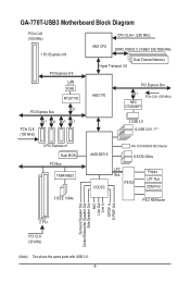
GA-770T-USB3 Motherboard Block Diagram PCIe CLK (100 MHz) 1 PCI Express x16 PCI Express x16 LAN RJ45 RTL8111D x1 PCI Express Bus CPU CLK+/- (200 MHz) AM3 CPU DDR3 1800(O.C.)/1666/1333/1066 MHz Dual Channel Memory Hyper Transport 3.0 AMD 770 PCI Express Bus x1 NEC D720200F1 PCIe CLK (100 MHz) PCIe CLK (...
GA-770T-USB3 Motherboard Block Diagram PCIe CLK (100 MHz) 1 PCI Express x16 PCI Express x16 LAN RJ45 RTL8111D x1 PCI Express Bus CPU CLK+/- (200 MHz) AM3 CPU DDR3 1800(O.C.)/1666/1333/1066 MHz Dual Channel Memory Hyper Transport 3.0 AMD 770 PCI Express Bus x1 NEC D720200F1 PCIe CLK (100 MHz) PCIe CLK (...
Manual
Page 9
... other hardware components. • When connecting hardware components to the internal connectors on the computer power during the installation process can become damaged as a motherboard, CPU or memory. ponents such as a result of the product, please consult a certified computer technician. - 9 - Chapter 1 Hardware Installation 1-1 Installation Precautions The motherboard contains numerous delicate electronic...
... other hardware components. • When connecting hardware components to the internal connectors on the computer power during the installation process can become damaged as a motherboard, CPU or memory. ponents such as a result of the product, please consult a certified computer technician. - 9 - Chapter 1 Hardware Installation 1-1 Installation Precautions The motherboard contains numerous delicate electronic...

Manual
Page 10
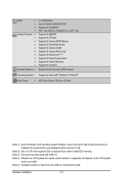
... for AM3 processors: AMD Phenom™ II processor/ AMD Athlon™ II processor (Go to GIGABYTE's website for the latest CPU support list.) Hyper Transport Bus 5200 MT/s Chipset Memory Audio ...GB of system memory (Note 1) Dual channel memory architecture Support for DDR3 1800 (O.C.)/1666/1333/1066 MHz memory modules (Go to GIGABYTE's website for the latest memory support list.) Support for ECC memory modules (Note 2) Realtek ALC888 codec High Definition Audio 2/4/5.1/7.1-channel...
... for AM3 processors: AMD Phenom™ II processor/ AMD Athlon™ II processor (Go to GIGABYTE's website for the latest CPU support list.) Hyper Transport Bus 5200 MT/s Chipset Memory Audio ...GB of system memory (Note 1) Dual channel memory architecture Support for DDR3 1800 (O.C.)/1666/1333/1066 MHz memory modules (Go to GIGABYTE's website for the latest memory support list.) Support for ECC memory modules (Note 2) Realtek ALC888 codec High Definition Audio 2/4/5.1/7.1-channel...
Manual
Page 11
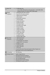
... IEEE 1394a header) Internal w 1 x 24-pin ATX main power connector Connectors w 1 x 8-pin ATX 12V power connector w 1 x floppy disk drive connector w 1 x IDE connector w 6 x SATA 3Gb/s connectors w 1 x CPU fan header w 2 x system fan headers w 1 x power fan header w 1 x front panel header w 1 x front panel audio header w 1 x CD In connector w 1 x S/PDIF In header w 1 x S/PDIF Out header w 2 x USB...
... IEEE 1394a header) Internal w 1 x 24-pin ATX main power connector Connectors w 1 x 8-pin ATX 12V power connector w 1 x floppy disk drive connector w 1 x IDE connector w 6 x SATA 3Gb/s connectors w 1 x CPU fan header w 2 x system fan headers w 1 x power fan header w 1 x front panel header w 1 x front panel audio header w 1 x CD In connector w 1 x S/PDIF In header w 1 x S/PDIF Out header w 2 x USB...
Manual
Page 12
..., when more than 4 GB of physical memory is installed, the actual memory size displayed will be less than 4 GB. (Note 2) Use of a CPU that supports ECC is required if you wish to install ECC memory. (Note 3) Two share the same ports with USB 3.0. (Note 4) Whether the... CPU/system fan speed control function is supported will depend on the CPU/system cooler you install. (Note 5) Available functions in EasyTune may differ by motherboard model. Hardware Installation - 12 -
..., when more than 4 GB of physical memory is installed, the actual memory size displayed will be less than 4 GB. (Note 2) Use of a CPU that supports ECC is required if you wish to install ECC memory. (Note 3) Two share the same ports with USB 3.0. (Note 4) Whether the... CPU/system fan speed control function is supported will depend on the CPU/system cooler you install. (Note 5) Available functions in EasyTune may differ by motherboard model. Hardware Installation - 12 -
Manual
Page 13
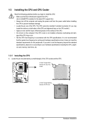
... damage. • Locate the pin one (denoted by a small triangle) of the CPU. If you may occur. • Set the CPU host frequency in accordance with the CPU specifications. The CPU cannot be set the frequency beyond the standard specifications, please do so according to set ...beyond hardware specifications since it does not meet the standard requirements for the latest CPU support list.) • Always turn on the computer if the CPU cooler is not recommended that the motherboard supports the CPU. (Go to GIGABYTE's website for the peripherals.
... damage. • Locate the pin one (denoted by a small triangle) of the CPU. If you may occur. • Set the CPU host frequency in accordance with the CPU specifications. The CPU cannot be set the frequency beyond the standard specifications, please do so according to set ...beyond hardware specifications since it does not meet the standard requirements for the latest CPU support list.) • Always turn on the computer if the CPU cooler is not recommended that the motherboard supports the CPU. (Go to GIGABYTE's website for the peripherals.
Manual
Page 14
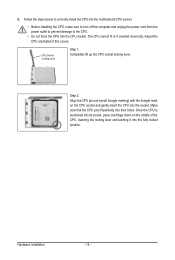
... into the socket. B. Hardware Installation - 14 - Make sure that the CPU pins fit perfectly into the CPU socket. Follow the steps below to correctly install the CPU into the motherboard CPU socket. • Before installing the CPU, make sure to turn off the computer and unplug the power cord from ...the power outlet to prevent damage to the CPU. • Do not force the CPU into their holes. Step 2: Align the CPU pin one ...
... into the socket. B. Hardware Installation - 14 - Make sure that the CPU pins fit perfectly into the CPU socket. Follow the steps below to correctly install the CPU into the motherboard CPU socket. • Before installing the CPU, make sure to turn off the computer and unplug the power cord from ...the power outlet to prevent damage to the CPU. • Do not force the CPU into their holes. Step 2: Align the CPU pin one ...
Manual
Page 15
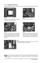
... manual for instructions on installing the cooler.) Step 5: Finally, attach the power connector of the CPU cooler to correctly install the CPU cooler on the CPU. (The following procedure uses the GIGABYTE cooler as the example.) Step 1: Apply an even and thin layer of thermal grease on the... surface of the retention frame. 1-3-2 Installing the CPU Cooler Follow the steps below to the CPU fan header (CPU_FAN)...
... manual for instructions on installing the cooler.) Step 5: Finally, attach the power connector of the CPU cooler to correctly install the CPU cooler on the CPU. (The following procedure uses the GIGABYTE cooler as the example.) Step 1: Apply an even and thin layer of thermal grease on the... surface of the retention frame. 1-3-2 Installing the CPU Cooler Follow the steps below to the CPU fan header (CPU_FAN)...

Manual
Page 16
.../SS DS/SS DS/SS (SS=Single-Sided, DS=Double-Sided, "- -"=No Memory) If two memory modules are to be used . (Go to GIGABYTE's website for optimum performance. When enabling Dual Channel mode with two or four memory modules, it is recommended that memory of the same capacity, brand... outlet before you begin to install the memory: • Make sure that the motherboard supports the memory. DDR3_1 DDR3_2 DDR3_3 DDR3_4 Due to CPU limitations, read the following guidelines before installing the memory in only one DDR3 memory module is installed, the BIOS will double the original memory ...
.../SS DS/SS DS/SS (SS=Single-Sided, DS=Double-Sided, "- -"=No Memory) If two memory modules are to be used . (Go to GIGABYTE's website for optimum performance. When enabling Dual Channel mode with two or four memory modules, it is recommended that memory of the same capacity, brand... outlet before you begin to install the memory: • Make sure that the motherboard supports the memory. DDR3_1 DDR3_2 DDR3_3 DDR3_4 Due to CPU limitations, read the following guidelines before installing the memory in only one DDR3 memory module is installed, the BIOS will double the original memory ...

Manual
Page 22
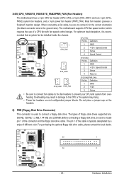
... 12V Power Connector and 2x12 Main Power Connector) With the use of the power connector, the power supply can supply enough stable power to the CPU. The 12V power connector mainly supplies power to all devices are properly installed. The power connector possesses a foolproof design.
... 12V Power Connector and 2x12 Main Power Connector) With the use of the power connector, the power supply can supply enough stable power to the CPU. The 12V power connector mainly supplies power to all devices are properly installed. The power connector possesses a foolproof design.
Manual
Page 23
... - 23 - Definition 1 CPU_FAN 1 GND 2 +12V / Speed Control 3 Sense 4 Speed Control SYS_FAN1: Pin No. The motherboard supports CPU fan speed control, which requires the use of the cable is the ground wire). The types of different color. Hardware Installation Most fan headers possess...jumper blocks. When connecting a fan cable, be installed inside the chassis. 3/4/5) CPU_FAN/SYS_FAN1/SYS_FAN2/PWR_FAN (Fan Headers) The motherboard has a 4-pin CPU fan header (CPU_FAN), a 4-pin (SYS_FAN1) and one 3-pin (SYS_ FAN2) system fan headers, and a 3-pin power fan header (PWR_FAN)....
... - 23 - Definition 1 CPU_FAN 1 GND 2 +12V / Speed Control 3 Sense 4 Speed Control SYS_FAN1: Pin No. The motherboard supports CPU fan speed control, which requires the use of the cable is the ground wire). The types of different color. Hardware Installation Most fan headers possess...jumper blocks. When connecting a fan cable, be installed inside the chassis. 3/4/5) CPU_FAN/SYS_FAN1/SYS_FAN2/PWR_FAN (Fan Headers) The motherboard has a 4-pin CPU fan header (CPU_FAN), a 4-pin (SYS_FAN1) and one 3-pin (SYS_ FAN2) system fan headers, and a 3-pin power fan header (PWR_FAN)....
Manual
Page 33
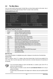
... Optimized Defaults Set Supervisor Password Set User Password Save & Exit Setup Exit Without Saving ESC: Quit F8: Q-Flash Select Item F10: Save & Exit Setup Change CPU's Clock & Voltage F11: Save CMOS to BIOS F12: Load CMOS from BIOS Main Menu Help The on-screen description of a highlighted setup option is displayed...
... Optimized Defaults Set Supervisor Password Set User Password Save & Exit Setup Exit Without Saving ESC: Quit F8: Q-Flash Select Item F10: Save & Exit Setup Change CPU's Clock & Voltage F11: Save CMOS to BIOS F12: Load CMOS from BIOS Main Menu Help The on-screen description of a highlighted setup option is displayed...
Manual
Page 34
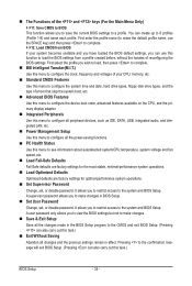
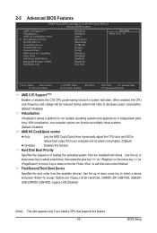
...that stop the system boot, etc. Advanced BIOS Features Use this menu to configure the device boot order, advanced features available on the CPU, and the primary display adapter. Integrated Peripherals Use this menu to configure all peripheral devices, such as IDE, SATA, USB, integrated ...to make changes. Save & Exit Setup Save all the changes made in the BIOS Setup program to see information about autodetected system/CPU temperature, system voltage and fan speed, etc. Load Fail-Safe Defaults Fail-Safe defaults are factory settings for the most stable, ...
...that stop the system boot, etc. Advanced BIOS Features Use this menu to configure the device boot order, advanced features available on the CPU, and the primary display adapter. Integrated Peripherals Use this menu to configure all peripheral devices, such as IDE, SATA, USB, integrated ...to make changes. Save & Exit Setup Save all the changes made in the BIOS Setup program to see information about autodetected system/CPU temperature, system voltage and fan speed, etc. Load Fail-Safe Defaults Fail-Safe defaults are factory settings for the most stable, ...
Manual
Page 35
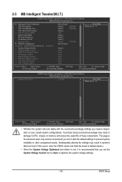
... prevent system instability or other unexpected results. (Inadequately altering the settings may result in system's failure to boot. CPU Host Clock Control x CPU Frequency(MHz) PCIE Clock(MHz) HT Link Frequency Set Memory Clock x Memory Clock } DRAM Configuration ******** System ...Control x DRAM Voltage Control x DDR VTT Voltage Control x NB Voltage Control x SB/HT Voltage Control x NB PCIE Voltage Control x CPU NB VID Control x CPU Voltage Control [Press Enter] [Auto] 2800Mhz [Auto] 2000Mhz [Auto] 200 [Auto] [Auto] [Auto] x6.66 1333Mhz [Press...
... prevent system instability or other unexpected results. (Inadequately altering the settings may result in system's failure to boot. CPU Host Clock Control x CPU Frequency(MHz) PCIE Clock(MHz) HT Link Frequency Set Memory Clock x Memory Clock } DRAM Configuration ******** System ...Control x DRAM Voltage Control x DDR VTT Voltage Control x NB Voltage Control x SB/HT Voltage Control x NB PCIE Voltage Control x CPU NB VID Control x CPU Voltage Control [Press Enter] [Auto] 2800Mhz [Auto] 2000Mhz [Auto] 200 [Auto] [Auto] [Auto] x6.66 1333Mhz [Press...
Manual
Page 36
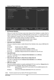
... (Core 2), Value (Core 3) This option is configurable only when Advanced Clock Calibration is present only if you install a CPU that supports this function. (Default) Auto Lets the BIOS to configure the settings to be configurable. BIOS Setup - 36 ... Selection Advanced Clock Calibration x Value (All Cores) x Value (Core 0) x Value (Core 1) x Value (Core 2) x Value (Core 3) CPU core Control x CPU core 2 (Note) x CPU core 3 (Note) [Normal] [Disabled] -2% -2% -2% -2% -2% [Auto] Enabled Enabled Item Help Menu Level Move Enter: Select...
... (Core 2), Value (Core 3) This option is configurable only when Advanced Clock Calibration is present only if you install a CPU that supports this function. (Default) Auto Lets the BIOS to configure the settings to be configurable. BIOS Setup - 36 ... Selection Advanced Clock Calibration x Value (All Cores) x Value (Core 0) x Value (Core 1) x Value (Core 2) x Value (Core 3) CPU core Control x CPU core 2 (Note) x CPU core 3 (Note) [Normal] [Disabled] -2% -2% -2% -2% -2% [Auto] Enabled Enabled Item Help Menu Level Move Enter: Select...
Manual
Page 37
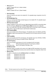
...frequency. Auto (default) allows the BIOS to X8.00. (Note) This item is from 200 MHz to 500 MHz. Manual allows the CPU Frequency (MHz) item below to be configurable. X4.00 Sets Memory Clock to be configurable. (Default: Auto) Memory Clock This option is...configurable only when Set Memory Clock is dependent on the CPU being used . The adjustable range is set to 200 MHz~2 GHz. CPU core 2 (Note) Enables or disables CPU Core 2. (Default: Enabled) CPU core 3 (Note) Enables or disables CPU Core 3. (Default: Enabled) CPU Clock Ratio Allows you to alter the clock ratio ...
...frequency. Auto (default) allows the BIOS to X8.00. (Note) This item is from 200 MHz to 500 MHz. Manual allows the CPU Frequency (MHz) item below to be configurable. X4.00 Sets Memory Clock to be configurable. (Default: Auto) Memory Clock This option is...configurable only when Set Memory Clock is dependent on the CPU being used . The adjustable range is set to 200 MHz~2 GHz. CPU core 2 (Note) Enables or disables CPU Core 2. (Default: Enabled) CPU core 3 (Note) Enables or disables CPU Core 3. (Default: Enabled) CPU Clock Ratio Allows you to alter the clock ratio ...

Manual
Page 40
... is dependent on the CPU being installed. (Default: Normal) Note: Increasing CPU voltage may result in damage to your CPU or reduce the useful life of your CPU or reduce the useful life of the CPU. Auto sets the CPU voltage as required. Normal CPU Vcore Displays the normal ...PCIe voltage as required. (Default) 1.800V ~ 2.200V The adjustable range is dependent on the CPU being installed. (Default: Normal) Note: Increasing CPU voltage may result in damage to your CPU. CPU Voltage Control Allows you to set the North Bridge PCIe voltage. The adjustable range is from 1....
... is dependent on the CPU being installed. (Default: Normal) Note: Increasing CPU voltage may result in damage to your CPU or reduce the useful life of your CPU or reduce the useful life of the CPU. Auto sets the CPU voltage as required. Normal CPU Vcore Displays the normal ...PCIe voltage as required. (Default) 1.800V ~ 2.200V The adjustable range is dependent on the CPU being installed. (Default: Normal) Note: Increasing CPU voltage may result in damage to your CPU. CPU Voltage Control Allows you to set the North Bridge PCIe voltage. The adjustable range is from 1....
Manual
Page 43
... computer system can function as multiple virtual systems. (Default: Disabled) AMD K8 Cool&Quiet control Auto Lets the AMD Cool'n'Quiet driver dynamically adjust the CPU clock and VID to HDD Init Display First [Disabled] [Disabled] [Auto] [Press Enter] [Hard Disk] [CDROM] [Floppy] [Setup] [Disabled] [Disabled]... or down arrow key to select a device and press to move it up or down on the list. When enabled, the CPU core frequency and voltage will be reduced during system halt state to decrease power consumption. (Default: Disabled) Virtualization Virtualization allows a platform...
... computer system can function as multiple virtual systems. (Default: Disabled) AMD K8 Cool&Quiet control Auto Lets the AMD Cool'n'Quiet driver dynamically adjust the CPU clock and VID to HDD Init Display First [Disabled] [Disabled] [Auto] [Press Enter] [Hard Disk] [CDROM] [Floppy] [Setup] [Disabled] [Disabled]... or down arrow key to select a device and press to move it up or down on the list. When enabled, the CPU core frequency and voltage will be reduced during system halt state to decrease power consumption. (Default: Disabled) Virtualization Virtualization allows a platform...
Manual
Page 50
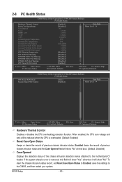
... Fail-Safe Defaults ESC: Exit F1: General Help F7: Optimized Defaults CMOS Setup Utility-Copyright (C) 1984-2009 Award Software PC Health Status CPU Smart FAN Mode System Smart FAN Control [Auto] [Enabled] Item Help Menu Level Move Enter: Select F5: Previous Values +/-/PU...Value F10: Save F6: Fail-Safe Defaults ESC: Exit F1: General Help F7: Optimized Defaults Hardware Thermal Control Enables or disables the CPU overheating protection function. BIOS Setup - 50 - Enabled clears the record of the chassis intrusion detection device attached to the CMOS, and...
... Fail-Safe Defaults ESC: Exit F1: General Help F7: Optimized Defaults CMOS Setup Utility-Copyright (C) 1984-2009 Award Software PC Health Status CPU Smart FAN Mode System Smart FAN Control [Auto] [Enabled] Item Help Menu Level Move Enter: Select F5: Previous Values +/-/PU...Value F10: Save F6: Fail-Safe Defaults ESC: Exit F1: General Help F7: Optimized Defaults Hardware Thermal Control Enables or disables the CPU overheating protection function. BIOS Setup - 50 - Enabled clears the record of the chassis intrusion detection device attached to the CMOS, and...


