Manual
Page 5
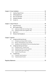
... 71 5-1-2 Making a SATA RAID/AHCI Driver Diskette 76 5-1-3 Installing the SATA RAID/AHCI Driver and Operating System 77 5-2 ConfiguringAudio Input and Output 82 5-2-1 Configuring 2/4/5.1-Channel Audio 82 5-2-2 Installing the S/PDIF Out Cable (Optional 85 5-2-3 Configuring Microphone Recording 87 5-2-4 Using the Sound Recorder 89 5-3 Troubleshooting 90 5-3-1 Frequently Asked Questions 90 5-3-2 Troubleshooting Procedure...
... 71 5-1-2 Making a SATA RAID/AHCI Driver Diskette 76 5-1-3 Installing the SATA RAID/AHCI Driver and Operating System 77 5-2 ConfiguringAudio Input and Output 82 5-2-1 Configuring 2/4/5.1-Channel Audio 82 5-2-2 Installing the S/PDIF Out Cable (Optional 85 5-2-3 Configuring Microphone Recording 87 5-2-4 Using the Sound Recorder 89 5-3 Troubleshooting 90 5-3-1 Frequently Asked Questions 90 5-3-2 Troubleshooting Procedure...
Manual
Page 7
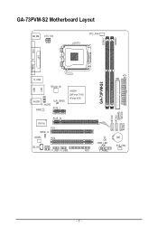
GA-73PVM-S2 Motherboard Layout KB_MS ATX_12V LGA775 CPU_FAN DDRII1 DDRII2 DVI LPT LAN VGA USB R_USB RTL8211B AUDIO F_AUDIO BIOS CLR_CMOS PCIE_1 nVIDIA® GeForce 7100/ nForce 630i PCIE_16 IT8718 PCI1 SPDIF_O CODEC PCI2 CD_IN COMA F_USB1 F_USB2 FDD ATX IDE GA-73PVM-S2 SATAII0 SATAII2 SATAII1 SATAII3 CI PWR_LED F_PANEL BAT SYS_FAN - 7 -
GA-73PVM-S2 Motherboard Layout KB_MS ATX_12V LGA775 CPU_FAN DDRII1 DDRII2 DVI LPT LAN VGA USB R_USB RTL8211B AUDIO F_AUDIO BIOS CLR_CMOS PCIE_1 nVIDIA® GeForce 7100/ nForce 630i PCIE_16 IT8718 PCI1 SPDIF_O CODEC PCI2 CD_IN COMA F_USB1 F_USB2 FDD ATX IDE GA-73PVM-S2 SATAII0 SATAII2 SATAII1 SATAII3 CI PWR_LED F_PANEL BAT SYS_FAN - 7 -
Manual
Page 10
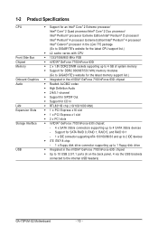
...® 4 processor Extreme Edition/Intel® Pentium® 4 processor/ Intel® Celeron® processor in the LGA 775 package (Go to GIGABYTE's website for the latest CPU support list.) Š L2 cache varies with CPU Š 1333/1066/800 MHz FSB Š nVIDIA® GeForce... Audio Š 2/4/5.1-channel Š Support for S/PDIF Out Š Support for SATA RAID 0, RAID 1, RAID 5, and RAID 0+1 - 1 x IDE connector supporting ATA-133/100/66/33 and up to 2 IDE devices Š iTE IT8718 chip: - 1 x floppy disk drive connector supporting up to the internal USB headers) GA-73PVM-S2 ...
...® 4 processor Extreme Edition/Intel® Pentium® 4 processor/ Intel® Celeron® processor in the LGA 775 package (Go to GIGABYTE's website for the latest CPU support list.) Š L2 cache varies with CPU Š 1333/1066/800 MHz FSB Š nVIDIA® GeForce... Audio Š 2/4/5.1-channel Š Support for S/PDIF Out Š Support for SATA RAID 0, RAID 1, RAID 5, and RAID 0+1 - 1 x IDE connector supporting ATA-133/100/66/33 and up to 2 IDE devices Š iTE IT8718 chip: - 1 x floppy disk drive connector supporting up to the internal USB headers) GA-73PVM-S2 ...
Manual
Page 11
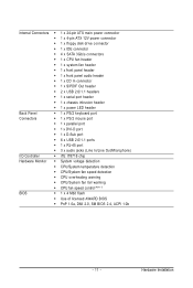
...138; 4 x SATA 3Gb/s connectors Š 1 x CPU fan header Š 1 x system fan header Š 1 x front panel header Š 1 x front panel audio header Š 1 x CD In connector Š 1 x S/PDIF Out header Š 2 x USB 2.0/1.1 headers Š 1 x serial port header Š 1 x chassis... Š 1 x DVI-D port Š 1 x D-Sub port Š 6 x USB 2.0/1.1 ports Š 1 x RJ-45 port Š 3 x audio jacks (Line In/Line Out/Microphone) I/O Controller Š iTE IT8718 chip Hardware Monitor Š System voltage detection Š CPU/System temperature detection Š CPU/System...
...138; 4 x SATA 3Gb/s connectors Š 1 x CPU fan header Š 1 x system fan header Š 1 x front panel header Š 1 x front panel audio header Š 1 x CD In connector Š 1 x S/PDIF Out header Š 2 x USB 2.0/1.1 headers Š 1 x serial port header Š 1 x chassis... Š 1 x DVI-D port Š 1 x D-Sub port Š 6 x USB 2.0/1.1 ports Š 1 x RJ-45 port Š 3 x audio jacks (Line In/Line Out/Microphone) I/O Controller Š iTE IT8718 chip Hardware Monitor Š System voltage detection Š CPU/System temperature detection Š CPU/System...

Manual
Page 19
Line In Jack (Blue) The default line in jack. Mic In Jack (Pink) The default Mic in jack. Microphones must be used to connect front speakers in devices such as an optical drive, walkman, etc. Refer to this jack. Use this audio jack for line in a 4/5.1-channel audio configuration. This jack can be connected to the instructions on setting up a 2/4/5.1-channel audio configuration in Chapter 5, "Configuring 2/4/5.1-Channel Audio." - 19 - Hardware Installation Use this audio jack for a headphone or 2-channel speaker. Line Out Jack (Green) The default line out jack.
Line In Jack (Blue) The default line in jack. Mic In Jack (Pink) The default Mic in jack. Microphones must be used to connect front speakers in devices such as an optical drive, walkman, etc. Refer to this jack. Use this audio jack for line in a 4/5.1-channel audio configuration. This jack can be connected to the instructions on setting up a 2/4/5.1-channel audio configuration in Chapter 5, "Configuring 2/4/5.1-Channel Audio." - 19 - Hardware Installation Use this audio jack for a headphone or 2-channel speaker. Line Out Jack (Green) The default line out jack.
Manual
Page 26
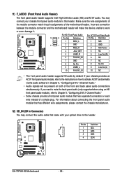
... of the front and back panel audio connections simultaneously. If you want to mute the back panel audio (only supported when using an HD front panel audio module), refer to work or even damage it. Definition 1 CD-L 2 GND 3 GND 4 CD-R GA-73PVM-S2 Motherboard - 26 - Make sure ...the wire assignments of the module connector match the pin assignments of a single plug. For HD Front Panel Audio: For AC'97 Front Panel Audio: 10 9 Pin No. Incorrect connection between the module connector ...
... of the front and back panel audio connections simultaneously. If you want to mute the back panel audio (only supported when using an HD front panel audio module), refer to work or even damage it. Definition 1 CD-L 2 GND 3 GND 4 CD-R GA-73PVM-S2 Motherboard - 26 - Make sure ...the wire assignments of the module connector match the pin assignments of a single plug. For HD Front Panel Audio: For AC'97 Front Panel Audio: 10 9 Pin No. Incorrect connection between the module connector ...

Manual
Page 27
Each USB header can connect to an audio device that supports digital audio in damage to the device. 14) F_USB1/F_USB2 (USB Headers) The headers conform to the USB bracket. - 27 - Hardware Installation For purchasing the optional USB ...
Each USB header can connect to an audio device that supports digital audio in damage to the device. 14) F_USB1/F_USB2 (USB Headers) The headers conform to the USB bracket. - 27 - Hardware Installation For purchasing the optional USB ...
Manual
Page 34
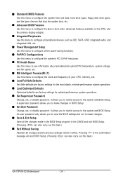
..., such as IDE, SATA, USB, integrated audio, and integrated LAN, etc. „ Power Management Setup Use this menu to configure all changes and the previous settings remain in effect. Pressing to the confirmation message will exit BIOS Setup. (Pressing can also carry out this task.) GA-73PVM-S2 Motherboard - 34 - A supervisor password allows you...
..., such as IDE, SATA, USB, integrated audio, and integrated LAN, etc. „ Power Management Setup Use this menu to configure all changes and the previous settings remain in effect. Pressing to the confirmation message will exit BIOS Setup. (Pressing can also carry out this task.) GA-73PVM-S2 Motherboard - 34 - A supervisor password allows you...
Manual
Page 40
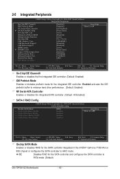
...for the SATA controller integrated in the nVIDIA® GeForce 7100/nForce 630i chipset or configures the SATA controller to PATA mode. (Default) GA-73PVM-S2 Motherboard - 40 - 2-5 Integrated Peripherals CMOS Setup Utility-Copyright (C) 1984-2007 Award Software Integrated Peripherals On-Chip IDE Channel0 IDE Prefetch ...-ATA Controller ` SATA-II RAID Config On-Chip MAC Lan Onboard LAN Boot ROM Onboard Audio Function On-Chip USB USB Memory Type USB Keyboard Support USB Mouse Support HDMI Audio ` SMART LAN Legacy USB storage detect Onboard Serial Port 1 Onboard Parallel Port Parallel Port ...
...for the SATA controller integrated in the nVIDIA® GeForce 7100/nForce 630i chipset or configures the SATA controller to PATA mode. (Default) GA-73PVM-S2 Motherboard - 40 - 2-5 Integrated Peripherals CMOS Setup Utility-Copyright (C) 1984-2007 Award Software Integrated Peripherals On-Chip IDE Channel0 IDE Prefetch ...-ATA Controller ` SATA-II RAID Config On-Chip MAC Lan Onboard LAN Boot ROM Onboard Audio Function On-Chip USB USB Memory Type USB Keyboard Support USB Mouse Support HDMI Audio ` SMART LAN Legacy USB storage detect Onboard Serial Port 1 Onboard Parallel Port Parallel Port ...

Manual
Page 41
... allocated for the SATA controller. USB Keyboard Support Allows USB keyboard to be used in MS-DOS. (Default: Disabled) HDMI Audio Enables or disables the HDMI audio function. (Default: Auto) - 41 - AHCI Configures the SATA controller to Disabled. SATA-II Pri-Master RAID Enables or ...ROM integrated with the onboard LAN chip. (Default: Disabled) Onboard Audio Function Enables or disables the onboard audio function. (Default: Auto) If you wish to install a 3rd party add-in audio card instead of using the onboard audio, set to RAID. (Default: Enabled) SATA-II Sec-Master ...
... allocated for the SATA controller. USB Keyboard Support Allows USB keyboard to be used in MS-DOS. (Default: Disabled) HDMI Audio Enables or disables the HDMI audio function. (Default: Auto) - 41 - AHCI Configures the SATA controller to Disabled. SATA-II Pri-Master RAID Enables or ...ROM integrated with the onboard LAN chip. (Default: Disabled) Onboard Audio Function Enables or disables the onboard audio function. (Default: Auto) If you wish to install a 3rd party add-in audio card instead of using the onboard audio, set to RAID. (Default: Enabled) SATA-II Sec-Master ...

Manual
Page 72
... NV Serial-ATA Controller ` SATA-II RAID Config On-Chip MAC Lan Onboard LAN Boot ROM Onboard Audio Function On-Chip USB USB Memory Type USB Keyboard Support USB Mouse Support HDMI Audio ` SMART LAN Legacy USB storage detect Onboard Serial Port 1 Onboard Parallel Port Parallel Port Mode x... KLJI: Move Enter: Select F5: Previous Values +/-/PU/PD: Value F10: Save F6: Fail-Safe Defaults Step 2: Save changes and exit BIOS Setup. GA-73PVM-S2 Motherboard - 72 - Configuring SATA controller mode in BIOS Setup Make sure to the SATA-II RAID Config submenu (Figure 2). B. Then, go to configure ...
... NV Serial-ATA Controller ` SATA-II RAID Config On-Chip MAC Lan Onboard LAN Boot ROM Onboard Audio Function On-Chip USB USB Memory Type USB Keyboard Support USB Mouse Support HDMI Audio ` SMART LAN Legacy USB storage detect Onboard Serial Port 1 Onboard Parallel Port Parallel Port Mode x... KLJI: Move Enter: Select F5: Previous Values +/-/PU/PD: Value F10: Save F6: Fail-Safe Defaults Step 2: Save changes and exit BIOS Setup. GA-73PVM-S2 Motherboard - 72 - Configuring SATA controller mode in BIOS Setup Make sure to the SATA-II RAID Config submenu (Figure 2). B. Then, go to configure ...

Manual
Page 82
... panel which support 2/4/5.1-channel(Note) audio. High Definition Audio (HD Audio) HD Audio includes multiple high quality digital-to-analog converters (DACs) that allow multiple audio streams (in your operating system has been updated with the latest Service Pack for Windows. (Note) 2/4/5.1-Channel Audio Configurations: Refer to access the Audio Control Panel. GA-73PVM-S2 Motherboard - 82 - If you want...
... panel which support 2/4/5.1-channel(Note) audio. High Definition Audio (HD Audio) HD Audio includes multiple high quality digital-to-analog converters (DACs) that allow multiple audio streams (in your operating system has been updated with the latest Service Pack for Windows. (Note) 2/4/5.1-Channel Audio Configurations: Refer to access the Audio Control Panel. GA-73PVM-S2 Motherboard - 82 - If you want...

Manual
Page 83
Select the device according to an audio jack, the Connected device box appears. Front Speaker Out Rear Speaker Out Center/Subwoofer Speaker Out - 83 - Step 3: The pictures to the right show the 2-, 4-, 5.1-...channel speaker configurations. 2-Channel Speakers: 4-Channel Speakers: Speakers or Headphones Front Speaker Out Rear Speaker Out 5.1-Channel Speakers: Step 4: Everytime you connect an audio device to the type of speaker configuration you connect. Then click OK to set up. Appendix In the speaker list on the left, select 2CH...
Select the device according to an audio jack, the Connected device box appears. Front Speaker Out Rear Speaker Out Center/Subwoofer Speaker Out - 83 - Step 3: The pictures to the right show the 2-, 4-, 5.1-...channel speaker configurations. 2-Channel Speakers: 4-Channel Speakers: Speakers or Headphones Front Speaker Out Rear Speaker Out 5.1-Channel Speakers: Step 4: Everytime you connect an audio device to the type of speaker configuration you connect. Then click OK to set up. Appendix In the speaker list on the left, select 2CH...

Manual
Page 84
GA-73PVM-S2 Motherboard - 84 - Muting the Back Panel Audio (For HD Audio Only): Click the tool icon on the Audio I /O tab On the Connector Settings box, select the Disable front panel jack detection check box. Click OK to activiate the AC'97 functionality. C. On the ... box, select the Mute rear panel output when front headphone plugged in check box. Activating an AC'97 Front Panel Audio Module: If you want to connect an AC'97 front panel audio module, click the tool icon on the Sound Effect tab. Click OK to complete. D. B. Configuring Sound Effect: You may...
GA-73PVM-S2 Motherboard - 84 - Muting the Back Panel Audio (For HD Audio Only): Click the tool icon on the Audio I /O tab On the Connector Settings box, select the Disable front panel jack detection check box. Click OK to activiate the AC'97 functionality. C. On the ... box, select the Mute rear panel output when front headphone plugged in check box. Activating an AC'97 Front Panel Audio Module: If you want to connect an AC'97 front panel audio module, click the tool icon on the Sound Effect tab. Click OK to complete. D. B. Configuring Sound Effect: You may...

Manual
Page 85
.... Optical S/PDIF Out Coaxial S/PDIFOut S/PDIF out: The S/PDIF out jacks can transmit audio signals to an external decoder for decoding to the chassis back panel with pin 1 of the cable to the device. Installing the S/PDIF Out Cable: ... with a screw. - 85 - Incorrect connection may render the device unusable or even result in and out cable first if you want to output S/PDIF digital audio signals to an external decoder. Install the S/PDIF in damage to the SPDIF_O header on your motherboard. 5-2-2 Installing the S/PDIF Out Cable (Optional) The S/PDIF...
.... Optical S/PDIF Out Coaxial S/PDIFOut S/PDIF out: The S/PDIF out jacks can transmit audio signals to an external decoder for decoding to the chassis back panel with pin 1 of the cable to the device. Installing the S/PDIF Out Cable: ... with a screw. - 85 - Incorrect connection may render the device unusable or even result in and out cable first if you want to output S/PDIF digital audio signals to an external decoder. Install the S/PDIF in damage to the SPDIF_O header on your motherboard. 5-2-2 Installing the S/PDIF Out Cable (Optional) The S/PDIF...

Manual
Page 86
Configuring S/PDIF out: Click the tool icon in the DIGITAL section. S/PDIF Coaxial Cable Step 3: Connect a S/PDIF coaxial cable or a S/PDIF optical cable (either one) to complete the configuration. Click OK to an external decoder for transmitting the S/PDIF digital audio signals. In the S/PDIF Settings dialog box, select an output sampling rate and select (or disable) the output source. GA-73PVM-S2 Motherboard - 86 - S/PDIF Optical Cable B.
Configuring S/PDIF out: Click the tool icon in the DIGITAL section. S/PDIF Coaxial Cable Step 3: Connect a S/PDIF coaxial cable or a S/PDIF optical cable (either one) to complete the configuration. Click OK to an external decoder for transmitting the S/PDIF digital audio signals. In the S/PDIF Settings dialog box, select an output sampling rate and select (or disable) the output source. GA-73PVM-S2 Motherboard - 86 - S/PDIF Optical Cable B.

Manual
Page 87
Doubleclick the icon to open the volume control panel. - 87 - Step 3: Locate the Volume icon in your system tray. Note: The microphone functions on the front panel and back panel cannot be used at the same time. Step 2: Connect your microphone to the Mic in jack (pink) on the back panel or the Line in your system tray and click it to access the Audio Control Panel. Appendix 5-2-3 Configuring Microphone Recording Step 1: After installing the audio driver, the Audio Manager icon will appear in jack on the front panel. Then configure the jack for microphone functionality.
Doubleclick the icon to open the volume control panel. - 87 - Step 3: Locate the Volume icon in your system tray. Note: The microphone functions on the front panel and back panel cannot be used at the same time. Step 2: Connect your microphone to the Mic in jack (pink) on the back panel or the Line in your system tray and click it to access the Audio Control Panel. Appendix 5-2-3 Configuring Microphone Recording Step 1: After installing the audio driver, the Audio Manager icon will appear in jack on the front panel. Then configure the jack for microphone functionality.

Manual
Page 88
... made. Step 5: Next, while in the Mixer device list GA-73PVM-S2 Motherboard Recording Control - 88 - Then set the volume at its middle level. (Note) If you cannot find the volume control options you set the recording sound level properly. Select Realtek HD Audio Input in Master Volume, go to the Options menu and... not select the Mute check box under Front Pink In or Front Green In in Master Volume. In the Mixer device list, select Realtek HD Audio Input.
... made. Step 5: Next, while in the Mixer device list GA-73PVM-S2 Motherboard Recording Control - 88 - Then set the volume at its middle level. (Note) If you cannot find the volume control options you set the recording sound level properly. Select Realtek HD Audio Input in Master Volume, go to the Options menu and... not select the Mute check box under Front Pink In or Front Green In in Master Volume. In the Mixer device list, select Realtek HD Audio Input.

Manual
Page 89
... Green In, Front Pink In). On the File menu, choose New. 3. In the Open dialog box, select the sound (.wav) file you have connected the audio input device (e.g. Playing the Sound: 1. Appendix Be sure to Options in Master Volume and select Advanced Controls. To play . 3. On the File menu, choose Open...
... Green In, Front Pink In). On the File menu, choose New. 3. In the Open dialog box, select the sound (.wav) file you have connected the audio input device (e.g. Playing the Sound: 1. Appendix Be sure to Options in Master Volume and select Advanced Controls. To play . 3. On the File menu, choose Open...


