Manual
Page 3
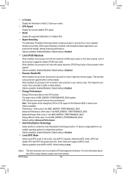
...-6PXSV2/GA-6PXSV3 Motherboard Layout 6 Chapter 1 Hardware Installation 9 1-1 Installation Precautions 9 1-2 Product Specifications 10 1-3 Installing the CPU and CPU Cooler 12 1-3-1 Installing the CPU...12 1-4 Installing the Memory 14 1-4-1 Four Channel Memory Configuration 14 1-4-2 Installing a Memory 15 1-4-3 DIMM Population Table 15 1-5 Back Panel Connectors 16 1-6 Internal Connectors 18 Chapter 2 BIOS Setup 33 2-1 The Main Menu 35 2-2 Advanced Menu 37 2-2-1 PCI Configuration...38 2-2-2 Trusted Computing 39 2-2-3 CPU Configuration 40 2-2-4 Runtime Error Logging 44 2-2-5 SATA...
...-6PXSV2/GA-6PXSV3 Motherboard Layout 6 Chapter 1 Hardware Installation 9 1-1 Installation Precautions 9 1-2 Product Specifications 10 1-3 Installing the CPU and CPU Cooler 12 1-3-1 Installing the CPU...12 1-4 Installing the Memory 14 1-4-1 Four Channel Memory Configuration 14 1-4-2 Installing a Memory 15 1-4-3 DIMM Population Table 15 1-5 Back Panel Connectors 16 1-6 Internal Connectors 18 Chapter 2 BIOS Setup 33 2-1 The Main Menu 35 2-2 Advanced Menu 37 2-2-1 PCI Configuration...38 2-2-2 Trusted Computing 39 2-2-3 CPU Configuration 40 2-2-4 Runtime Error Logging 44 2-2-5 SATA...
Manual
Page 7
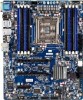
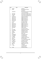
... port and USB connectors (GA-6PXSV2) LAN connector and USB connectors LAN connector and USB connectors USB connectors (GA-6PXSV3 Only) Serial port and VGA port DIMM slot (channel A-0) DIMM slot (channel A-1) DIMM slot (channel B-0 ) DIMM slot (channel B-1 ) 8 pin power connector Intel LGA 2011 socket DIMM slot (channel D-1 ) DIMM slot (channel D-0 ) DIMM slot (channel C-1 ) DIMM slot (channel C-0 ) PMBus connector 24 pin power connector System fan cable connectors SATA SGPIO connector SATA 6Gb/s connectors SATA 3Gb/s connectors Battery socket Clear password jumper Clear CMOS jumper Front panel...
... port and USB connectors (GA-6PXSV2) LAN connector and USB connectors LAN connector and USB connectors USB connectors (GA-6PXSV3 Only) Serial port and VGA port DIMM slot (channel A-0) DIMM slot (channel A-1) DIMM slot (channel B-0 ) DIMM slot (channel B-1 ) 8 pin power connector Intel LGA 2011 socket DIMM slot (channel D-1 ) DIMM slot (channel D-0 ) DIMM slot (channel C-1 ) DIMM slot (channel C-0 ) PMBus connector 24 pin power connector System fan cable connectors SATA SGPIO connector SATA 6Gb/s connectors SATA 3Gb/s connectors Battery socket Clear password jumper Clear CMOS jumper Front panel...
Manual
Page 8
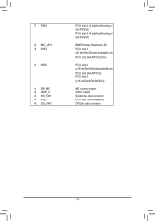
37 PCIE4 38 BMC_LED1 39 PCIE3 40 PCIE2 41 SSB_ME1 42 SPDIF_IN 43 SYS_FAN1 44 PCIE1 45 CPU_FAN1 PCI-E slot 4 (x4 slot/Gen2/running x1/ GA-6PXSV2) PCI-E slot 4 (x4 slot/Gen2/running x2/ GA-6PXSV3) BMC Firmware Readiness LED PCI-E slot 3 (x8 slot/Gen3/Shared bandwidth with PCI-E slot 2/GA-6PXSV2 Only) PCI-E slot 2 (x16 slot/Gen3/Shared bandwidth with PCI-E slot 3/GA-6PXSV2) PCI-E slot 2 (x16 slot/Gen3/GA-6PXSV3) ME recovery jumper S/PDIF header System fan cable connector PCI-E slot 1 (x16 slot/Gen3) CPU fan cable connector - 8 -
37 PCIE4 38 BMC_LED1 39 PCIE3 40 PCIE2 41 SSB_ME1 42 SPDIF_IN 43 SYS_FAN1 44 PCIE1 45 CPU_FAN1 PCI-E slot 4 (x4 slot/Gen2/running x1/ GA-6PXSV2) PCI-E slot 4 (x4 slot/Gen2/running x2/ GA-6PXSV3) BMC Firmware Readiness LED PCI-E slot 3 (x8 slot/Gen3/Shared bandwidth with PCI-E slot 2/GA-6PXSV2 Only) PCI-E slot 2 (x16 slot/Gen3/Shared bandwidth with PCI-E slot 3/GA-6PXSV2) PCI-E slot 2 (x16 slot/Gen3/GA-6PXSV3) ME recovery jumper S/PDIF header System fan cable connector PCI-E slot 1 (x16 slot/Gen3) CPU fan cable connector - 8 -
Manual
Page 9
... to the motherboard, do not remove or break motherboard S/N (Serial Number) sticker or warranty sticker provided by unplugging the power cord from the power outlet before installing or removing the motherboard or other hardware components. • When connecting hardware components to the internal connectors on the computer power during the installation process can become damaged as a motherboard, CPU or memory. Prior to installation, carefully read the user's manual and follow...
... to the motherboard, do not remove or break motherboard S/N (Serial Number) sticker or warranty sticker provided by unplugging the power cord from the power outlet before installing or removing the motherboard or other hardware components. • When connecting hardware components to the internal connectors on the computer power during the installation process can become damaged as a motherboard, CPU or memory. Prior to installation, carefully read the user's manual and follow...
Manual
Page 10
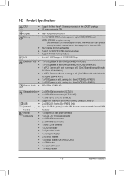
...138; 2 x SATA 6Gb/s connectors (SATA0/1) 4 x SATA 3Gb/s connectors (SATA2/3/4/5) 1 x SAS 3Gb/s connector (SAS0_3) Support for Intel RSTe SATA RAID 0, RAID 1, RAID 10, RAID 5 2 x USB 2.0/1.1 ports (GA-6PXSV2 Only) Up to 4 USB 3.0 ports (4 via the USB brackets connected to the internal USB headers) 1 x 24-pin ATX main power connector 1 x 8-pin ATX 12V power connector 4 x SATA 3Gb/s connectors 2 x SATA 6Gb/s connectors 1 x SAS 3Gb/s connector 1 x CPU fan header 3 x System fan header 1 x front panel header 2 x USB3.0 headers 1 x USB2.0 header (GA-6PXSV2 Only) 1 x TPM header 1 x serial port header...
...138; 2 x SATA 6Gb/s connectors (SATA0/1) 4 x SATA 3Gb/s connectors (SATA2/3/4/5) 1 x SAS 3Gb/s connector (SAS0_3) Support for Intel RSTe SATA RAID 0, RAID 1, RAID 10, RAID 5 2 x USB 2.0/1.1 ports (GA-6PXSV2 Only) Up to 4 USB 3.0 ports (4 via the USB brackets connected to the internal USB headers) 1 x 24-pin ATX main power connector 1 x 8-pin ATX 12V power connector 4 x SATA 3Gb/s connectors 2 x SATA 6Gb/s connectors 1 x SAS 3Gb/s connector 1 x CPU fan header 3 x System fan header 1 x front panel header 2 x USB3.0 headers 1 x USB2.0 header (GA-6PXSV2 Only) 1 x TPM header 1 x serial port header...
Manual
Page 11
Hardware Installation - 11 - Back Panel Connectors I/O Controller Hardware Monitor BIOS Form Factor ŠŠ 6 x USB 2.0/1.1 ports (GA-6PXSV3) ŠŠ 4 x USB 3.0 ports (GA-6PXSV2) ŠŠ 2 x USB 2.0/1.1 ports (GA-6PXSV2) ŠŠ 2 x RJ-45 LAN ports ŠŠ 1 x 10/100 Management LAN port ŠŠ 6 x Audio ports (4 x Line-out/1 x Line-in/1 x MIC) ŠŠ 1 x COM port ŠŠ 1 x VGA port ŠŠ iTE IT8728 chip ŠŠ System voltage detection ŠŠ CPU/System temperature detection ŠŠ CPU/System/Power fan speed detection...
Hardware Installation - 11 - Back Panel Connectors I/O Controller Hardware Monitor BIOS Form Factor ŠŠ 6 x USB 2.0/1.1 ports (GA-6PXSV3) ŠŠ 4 x USB 3.0 ports (GA-6PXSV2) ŠŠ 2 x USB 2.0/1.1 ports (GA-6PXSV2) ŠŠ 2 x RJ-45 LAN ports ŠŠ 1 x 10/100 Management LAN port ŠŠ 6 x Audio ports (4 x Line-out/1 x Line-in/1 x MIC) ŠŠ 1 x COM port ŠŠ 1 x VGA port ŠŠ iTE IT8728 chip ŠŠ System voltage detection ŠŠ CPU/System temperature detection ŠŠ CPU/System/Power fan speed detection...
Manual
Page 12
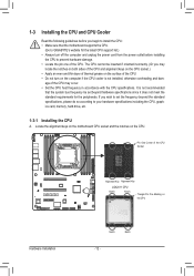
...- 1-3 Installing the CPU and CPU Cooler Read the following guidelines before installing the CPU to your hardware specifications including the CPU, graphics card, memory, hard drive, etc. 1-3-1 Installing the CPU A. The CPU cannot be set the frequency beyond hardware specifications since it does not meet the standard requirements for the latest CPU support list.) • Always turn on the computer if the CPU cooler is not recommended that the motherboard supports the CPU. (Go to GIGABYTE's website...
...- 1-3 Installing the CPU and CPU Cooler Read the following guidelines before installing the CPU to your hardware specifications including the CPU, graphics card, memory, hard drive, etc. 1-3-1 Installing the CPU A. The CPU cannot be set the frequency beyond hardware specifications since it does not meet the standard requirements for the latest CPU support list.) • Always turn on the computer if the CPU cooler is not recommended that the motherboard supports the CPU. (Go to GIGABYTE's website...
Manual
Page 14
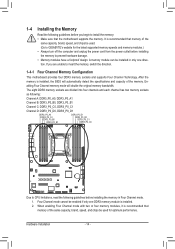
... the specifications and capacity of the same capacity, brand, speed, and chips be enabled if only one direction. A memory module can be used for the latest supported memory speeds and memory modules.) • Always turn off the computer and unplug the power cord from the power outlet before installing the memory to insert the memory, switch the direction. 1-4-1 Four Channel Memory Configuration This motherboard provides four DDR3 memory sockets and supports Four Channel Technology. When enabling Four Channel mode...
... the specifications and capacity of the same capacity, brand, speed, and chips be enabled if only one direction. A memory module can be used for the latest supported memory speeds and memory modules.) • Always turn off the computer and unplug the power cord from the power outlet before installing the memory to insert the memory, switch the direction. 1-4-1 Four Channel Memory Configuration This motherboard provides four DDR3 memory sockets and supports Four Channel Technology. When enabling Four Channel mode...
Manual
Page 15
...-Rank Dual-Rank Dual-Rank Dual-Rank - 15 - Installation Step: Step 1. Step 2. Reverse the installation steps when you wish to the memory module. Hardware Installation Close the plastic clip at both edges of the DIMM slots to install DDR3 DIMMs on this motherboard. Step 3. Insert the DIMM memory module vertically into the DIMM slot, and push it down. Note: For dual-channel and four-channel...
...-Rank Dual-Rank Dual-Rank Dual-Rank - 15 - Installation Step: Step 1. Step 2. Reverse the installation steps when you wish to the memory module. Hardware Installation Close the plastic clip at both edges of the DIMM slots to install DDR3 DIMMs on this motherboard. Step 3. Insert the DIMM memory module vertically into the DIMM slot, and push it down. Note: For dual-channel and four-channel...
Manual
Page 16
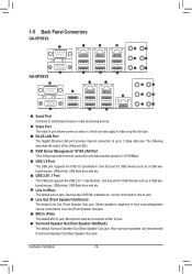
... to Line In jack. Rear surround speakers can be connected to Surround Speaker Out (Rear Speaker Out) jack. 1-5 Back Panel Connectors GA-6PXSV2 GA-6PXSV3 Serial Port Connects to Line Out (Front Speaker Out) jack. Use this port for USB devices such as a USB keyboard/mouse, USB printer, USB flash drive and etc. Line Out (Front Speaker Out/Green) The default Line Out (Front Speaker Out) jack. USB 3.0 Port The USB port supports the USB 3.0 specification. Line In (Blue) The default Line In jack.
... to Line In jack. Rear surround speakers can be connected to Surround Speaker Out (Rear Speaker Out) jack. 1-5 Back Panel Connectors GA-6PXSV2 GA-6PXSV3 Serial Port Connects to Line Out (Front Speaker Out) jack. Use this port for USB devices such as a USB keyboard/mouse, USB printer, USB flash drive and etc. Line Out (Front Speaker Out/Green) The default Line Out (Front Speaker Out) jack. USB 3.0 Port The USB port supports the USB 3.0 specification. Line In (Blue) The default Line In jack.
Manual
Page 20
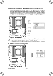
The motherboard supports CPU fan speed control, which requires the use of a CPU fan with fan speed control design. Do not place a jumper cap on the headers. 7) PWR_DET1 (Power management connector) Pin No. Most fan headers possess a foolproof insertion design. CPU_FAN1 SYS_FAN1 1 SYS_FAN1 1 CPU_FAN1 SYS_FAN2 SYS_FAN3 SYS_FAN2 Pin No. 1 2 3 4 Definition GND +12V Sense Speed Control SYS_FAN3 • Be sure to connect fan cables to the fan headers to connect it is the ground wire). When connecting a fan cable, be installed inside the chassis. Definition 1 SMB...
The motherboard supports CPU fan speed control, which requires the use of a CPU fan with fan speed control design. Do not place a jumper cap on the headers. 7) PWR_DET1 (Power management connector) Pin No. Most fan headers possess a foolproof insertion design. CPU_FAN1 SYS_FAN1 1 SYS_FAN1 1 CPU_FAN1 SYS_FAN2 SYS_FAN3 SYS_FAN2 Pin No. 1 2 3 4 Definition GND +12V Sense Speed Control SYS_FAN3 • Be sure to connect fan cables to the fan headers to connect it is the ground wire). When connecting a fan cable, be installed inside the chassis. Definition 1 SMB...

Manual
Page 26
... 6 NCTS- 7 NDTR- 8 NRI 9 GND 10 No Pin Hardware Installation - 26 - Pin No. Definition 2 10 1 Power (5V) 2 Power (5V) 3 USB DX- 1 9 4 USB DY5 USB DX+ 6 USB DY+ 7 GND 8 GND 9 No Pin 10 NC 16) COM2 (Serial Port Header) The COM header can provide two USB ports via an optional COM port cable. For purchasing the optional USB bracket, please contact the local dealer. DEBUG PORT 15) F_USB1 (Front USB Headers/GA-6PXSV2 Only) The headers conform to USB 2.0/1.1 specification.
... 6 NCTS- 7 NDTR- 8 NRI 9 GND 10 No Pin Hardware Installation - 26 - Pin No. Definition 2 10 1 Power (5V) 2 Power (5V) 3 USB DX- 1 9 4 USB DY5 USB DX+ 6 USB DY+ 7 GND 8 GND 9 No Pin 10 NC 16) COM2 (Serial Port Header) The COM header can provide two USB ports via an optional COM port cable. For purchasing the optional USB bracket, please contact the local dealer. DEBUG PORT 15) F_USB1 (Front USB Headers/GA-6PXSV2 Only) The headers conform to USB 2.0/1.1 specification.
Manual
Page 29
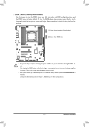
... pins to temporarily short the two pins or use a metal object like a screwdriver to remove the jumper cap from the jumper. 21) CLR_CMOS1 (Clearing CMOS Jumper) Use this jumper to factory defaults. Failure to do so may cause damage to the motherboard. • After system restart, go to BIOS Setup Exit menu and load factory defaults (select Load Default Values) or manually configure the BIOS settings (refer to Chapter 2, "BIOS Setup," for a few seconds. 1-2 Close: Normal operation (Default setting) 1 2-3 Close: Clear CMOS...
... pins to temporarily short the two pins or use a metal object like a screwdriver to remove the jumper cap from the jumper. 21) CLR_CMOS1 (Clearing CMOS Jumper) Use this jumper to factory defaults. Failure to do so may cause damage to the motherboard. • After system restart, go to BIOS Setup Exit menu and load factory defaults (select Load Default Values) or manually configure the BIOS settings (refer to Chapter 2, "BIOS Setup," for a few seconds. 1-2 Close: Normal operation (Default setting) 1 2-3 Close: Clear CMOS...
Manual
Page 32
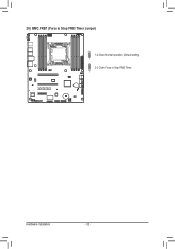
26) BMC_FRB1 (Force to Stop FRB3 Timer Jumper) 1-2 Close: Normal operation. (Default setting) 1 2-3 Close: Force to Stop FRB3 Timer. 1 Hardware Installation - 32 -
26) BMC_FRB1 (Force to Stop FRB3 Timer Jumper) 1-2 Close: Normal operation. (Default setting) 1 2-3 Close: Force to Stop FRB3 Timer. 1 Hardware Installation - 32 -
Manual
Page 33
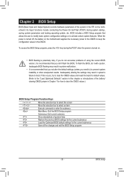
... using the current BIOS version, it with caution. To access the BIOS Setup program, press the key during system startup, saving system parameters and loading operating system, etc. If this occurs, try to clear the CMOS values and reset the board to default values. (Refer to the "Load Optimized Defaults" section in this chapter or introductions of the battery/ clearing CMOS jumper in the EFI on the motherboard supplies the necessary power...
... using the current BIOS version, it with caution. To access the BIOS Setup program, press the key during system startup, saving system parameters and loading operating system, etc. If this occurs, try to clear the CMOS values and reset the board to default values. (Refer to the "Load Optimized Defaults" section in this chapter or introductions of the battery/ clearing CMOS jumper in the EFI on the motherboard supplies the necessary power...
Manual
Page 38
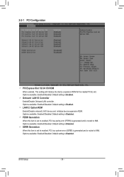
Onboard LAN1/2 Controller Enable/Disable Onboard LAN controller . Default setting is Disabled. Options available: Enabled/Disabled. Options available: Enabled/Disabled. BIOS Setup - 38 - Options available: Enabled/Disabled. Default setting is Disabled. Options available: Enabled/Disabled. Default setting is Enabled. LAN1/2 Option ROM Enable/Disable onboard LAN1 device and initialize device expansion ROM. Default setting is Enabled. Options available: Enabled/Disabled. SERR Generation When this item is set to enabled, PCI bus system error (SERR) is generated and is...
Onboard LAN1/2 Controller Enable/Disable Onboard LAN controller . Default setting is Disabled. Options available: Enabled/Disabled. Options available: Enabled/Disabled. BIOS Setup - 38 - Options available: Enabled/Disabled. Default setting is Disabled. Options available: Enabled/Disabled. Default setting is Enabled. LAN1/2 Option ROM Enable/Disable onboard LAN1 device and initialize device expansion ROM. Default setting is Enabled. Options available: Enabled/Disabled. SERR Generation When this item is set to enabled, PCI bus system error (SERR) is generated and is...
Manual
Page 42
... memory area. VT allows a single platform to Auto, use x2APIC if required, otherwise xAPIC mode. If set to run multiple operating systems in independent partitions. Some OSes don't support x2APIC mode. Options available: Enabled/Disabled. BIOS Setup - 42 - The larger value in MSR_ENERGY_PERFORMANCE_BIAS register, CPU will return the actual maximum CPUID input value of installed CPU. CPU Speed Display the current installed CPU speed. 64-bit Display the supported infprmation of the processor when queried. Default setting...
... memory area. VT allows a single platform to Auto, use x2APIC if required, otherwise xAPIC mode. If set to run multiple operating systems in independent partitions. Some OSes don't support x2APIC mode. Options available: Enabled/Disabled. BIOS Setup - 42 - The larger value in MSR_ENERGY_PERFORMANCE_BIAS register, CPU will return the actual maximum CPUID input value of installed CPU. CPU Speed Display the current installed CPU speed. 64-bit Display the supported infprmation of the processor when queried. Default setting...
Manual
Page 45
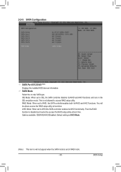
... SATA Configuration SATA Port 0/1/2/3/4/5 (Note) Displays the installed HDD devices information. SATA Mode Select the on chip SATA type. RAID Mode: When set to RAID, the SATA controllerenables both its RAID and AHCI functions. BIOS Setup AHCI Mode: When set to AHCI,the SATA controller enables its RAID and AHCI functions and runs in the IDE emulation mode. Options available: IDE/RAID/AHCI/Disabled. You will not appear when the SATA mode is will be access the RAID setup utility at boot time. Default setting is AHCI Mode. (Note) This item is set to access RAID setup...
... SATA Configuration SATA Port 0/1/2/3/4/5 (Note) Displays the installed HDD devices information. SATA Mode Select the on chip SATA type. RAID Mode: When set to RAID, the SATA controllerenables both its RAID and AHCI functions. BIOS Setup AHCI Mode: When set to AHCI,the SATA controller enables its RAID and AHCI functions and runs in the IDE emulation mode. Options available: IDE/RAID/AHCI/Disabled. You will not appear when the SATA mode is will be access the RAID setup utility at boot time. Default setting is AHCI Mode. (Note) This item is set to access RAID setup...

Manual
Page 47
...(HP SIR) Mode (High Speed)/ ASKIRfdgdg Mode. Default setting is Enabled. Change Settings Change Serial Port 1/2 device settings. Device Mode Change the Serial Port mode. When set to Auto allows the server's BIOS or OS to configure the serial port settings. IRQ=4/IO=3F8h; IRQ=3,4,5,6,7,10,11,12/IO=2E8h; Default setting is Standard Serial Port Mode. - 47 - Serial Port 1/2 Configuration Serial Port When enabled allows you to select a configuration. Options available: Enabled/Disabled. Options available: Auto/IO=3F8; IRQ=3,4,5,6,7,10,11,12/ IO=2F8h; BIOS Setup
...(HP SIR) Mode (High Speed)/ ASKIRfdgdg Mode. Default setting is Enabled. Change Settings Change Serial Port 1/2 device settings. Device Mode Change the Serial Port mode. When set to Auto allows the server's BIOS or OS to configure the serial port settings. IRQ=4/IO=3F8h; IRQ=3,4,5,6,7,10,11,12/IO=2E8h; Default setting is Standard Serial Port Mode. - 47 - Serial Port 1/2 Configuration Serial Port When enabled allows you to select a configuration. Options available: Enabled/Disabled. Options available: Auto/IO=3F8; IRQ=3,4,5,6,7,10,11,12/ IO=2F8h; BIOS Setup

Manual
Page 55
... WA's Enable/DIsable the support for Directed I/O Configuration VGA Priority Define the display device priority. IOH 0 PCIe port Bifurcation Control IOU1 - IOU3 - Default setting is Disabled. BIOS Setup - 55 - PCIe Port Options available: x4x4/x8. PCIe Port Options available: x4x4x4x4/x4x4x8/x8x4x4/x8x8/x16. PORT 1A Link Speed Options available: GEN1/GEN2/GEN3. PORT 3A Link Speed Options available: GEN1/GEN2/GEN3. Default setting is Disabled. Options available: Enabled/Disabled. PCIe Port Options available: x4x4x4x4/x4x4x8/x8x4x4/x8x8/x16. PORT 3C Link Speed...
... WA's Enable/DIsable the support for Directed I/O Configuration VGA Priority Define the display device priority. IOH 0 PCIe port Bifurcation Control IOU1 - IOU3 - Default setting is Disabled. BIOS Setup - 55 - PCIe Port Options available: x4x4/x8. PCIe Port Options available: x4x4x4x4/x4x4x8/x8x4x4/x8x8/x16. PORT 1A Link Speed Options available: GEN1/GEN2/GEN3. PORT 3A Link Speed Options available: GEN1/GEN2/GEN3. Default setting is Disabled. Options available: Enabled/Disabled. PCIe Port Options available: x4x4x4x4/x4x4x8/x8x4x4/x8x8/x16. PORT 3C Link Speed...


