Manual
Page 1
GA-6PXSV1 LGA 2011 socket motherboard for Intel® E5-1600/E5-2600 series processors User's Manual Rev. 1001
GA-6PXSV1 LGA 2011 socket motherboard for Intel® E5-1600/E5-2600 series processors User's Manual Rev. 1001
Manual
Page 3
Table of Contents Box Contents...4 GA-6PXSV1 Motherboard Layout 5 Chapter 1 Hardware Installation 8 1-1 Installation Precautions 8 1-2 Product Specifications 9 1-3 Installing the CPU and CPU Cooler 11 1-3-1 Installing the CPU...11 1-3-2 Installing the CPU Cooler 13 1-4 Installing ...
Table of Contents Box Contents...4 GA-6PXSV1 Motherboard Layout 5 Chapter 1 Hardware Installation 8 1-1 Installation Precautions 8 1-2 Product Specifications 9 1-3 Installing the CPU and CPU Cooler 11 1-3-1 Installing the CPU...11 1-3-2 Installing the CPU Cooler 13 1-4 Installing ...
Manual
Page 4
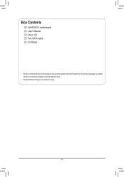
Box Contents GA-6PXSV1 motherboard User's Manual Driver CD Two SATA cables I/O Shield • The box contents above are subject to change without notice. • The motherboard image is for reference only and the actual items shall depend on the product package you obtain. The box contents are for reference only. - 4 -
Box Contents GA-6PXSV1 motherboard User's Manual Driver CD Two SATA cables I/O Shield • The box contents above are subject to change without notice. • The motherboard image is for reference only and the actual items shall depend on the product package you obtain. The box contents are for reference only. - 4 -
Manual
Page 5
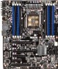
GA-6PXSV1 Motherboard Layout 37 38 39 40 42 41 43 1 2 3 4 5 6 36 35 3334 7 32 8 31 9 10 30 11 29 28 12 27 26 23 22 25 21 13 14 15 16 24 20 19 18 17 - 5 -
GA-6PXSV1 Motherboard Layout 37 38 39 40 42 41 43 1 2 3 4 5 6 36 35 3334 7 32 8 31 9 10 30 11 29 28 12 27 26 23 22 25 21 13 14 15 16 24 20 19 18 17 - 5 -
Manual
Page 8
...not have an ESD wrist strap, keep your hands dry and first touch a metal object to eliminate static electricity. • Prior to installing the motherboard, please have it on top of an antistatic pad or within the computer casing. • Do not place the computer system on an uneven ...warranty sticker provided by your hardware components are required for warranty validation. • Always remove the AC power by unplugging the power cord from the motherboard, make sure the power supply has been turned off. • Before turning on the power, make sure the power supply voltage has been set...
...not have an ESD wrist strap, keep your hands dry and first touch a metal object to eliminate static electricity. • Prior to installing the motherboard, please have it on top of an antistatic pad or within the computer casing. • Do not place the computer system on an uneven ...warranty sticker provided by your hardware components are required for warranty validation. • Always remove the AC power by unplugging the power cord from the motherboard, make sure the power supply has been turned off. • Before turning on the power, make sure the power supply voltage has been set...

Manual
Page 10
.... Remove the cover. B. Step 5: Once the CPU is opened.) Step 4: Hold the CPU with the socket alignment keys) and carefully insert the CPU into the motherboard CPU socket. •• Before installing the CPU, make sure to turn off from the power outlet to prevent damage to release it. Then secure...
.... Remove the cover. B. Step 5: Once the CPU is opened.) Step 4: Hold the CPU with the socket alignment keys) and carefully insert the CPU into the motherboard CPU socket. •• Before installing the CPU, make sure to turn off from the power outlet to prevent damage to release it. Then secure...

Manual
Page 11
... brand, speed, and chips be used . (Go to GIGABYTE's website for optimum performance. - 11 - The eight DDR3 memory sockets are unable to insert the memory, switch the direction. 1-4-1 Four Channel Memory Configuration This motherboard provides four DDR3 memory sockets and supports Four Channel Technology. ...1. A memory module can be enabled if only one direction. If you begin to install the memory: • Make sure that the motherboard supports the memory. When enabling Four Channel mode with two or four memory modules, it is recommended that memory of the memory. En-...
... brand, speed, and chips be used . (Go to GIGABYTE's website for optimum performance. - 11 - The eight DDR3 memory sockets are unable to insert the memory, switch the direction. 1-4-1 Four Channel Memory Configuration This motherboard provides four DDR3 memory sockets and supports Four Channel Technology. ...1. A memory module can be enabled if only one direction. If you begin to install the memory: • Make sure that the motherboard supports the memory. When enabling Four Channel mode with two or four memory modules, it is recommended that memory of the memory. En-...

Manual
Page 13
..., make sure your devices are compliant with the connectors you wish to connect. • Before installing the devices, be sure to the connector on the motherboard. - 13 - Unplug the power cord from the power outlet to prevent damage to the devices. • After installing the device and before connecting external devices...
..., make sure your devices are compliant with the connectors you wish to connect. • Before installing the devices, be sure to the connector on the motherboard. - 13 - Unplug the power cord from the power outlet to prevent damage to the devices. • After installing the device and before connecting external devices...

Manual
Page 14
When connecting a fan cable, be installed inside the chassis. 3/4/5/6) CPU_FAN1/SYS_FAN1/SYS_FAN2/SYS_FAN3 (CPU Fan/System Fan Headers) The motherboard has a 4-pin CPU fan header (FAN1), a 4-pin (FAN4) system fan headers. Overheating may result in the correct orientation (the black connector... headers are not configuration jumper blocks. Do not place a jumper cap on the headers. 7) PWR_LED1 (Power LED Header) 3 Pin No. The motherboard supports CPU fan speed control, which requires the use of a CPU fan with fan speed control design. For optimum heat dissipation, it is the ground...
When connecting a fan cable, be installed inside the chassis. 3/4/5/6) CPU_FAN1/SYS_FAN1/SYS_FAN2/SYS_FAN3 (CPU Fan/System Fan Headers) The motherboard has a 4-pin CPU fan header (FAN1), a 4-pin (FAN4) system fan headers. Overheating may result in the correct orientation (the black connector... headers are not configuration jumper blocks. Do not place a jumper cap on the headers. 7) PWR_LED1 (Power LED Header) 3 Pin No. The motherboard supports CPU fan speed control, which requires the use of a CPU fan with fan speed control design. For optimum heat dissipation, it is the ground...

Manual
Page 16
Locate the alignment keys on the motherboard CPU socket and the notches on the CPU Notch Notch - 16 - Alignment Key Alignment Key Pin One Corner of the CPU Socket Alignment Key Alignment ... standard requirements for the latest CPU support list.) • Always turn on the computer if the CPU cooler is not recommended that the motherboard supports the CPU. (Go to GIGABYTE's website for the peripherals. It is not installed, otherwise overheating and dam- If you may occur. • Set the CPU host frequency...
Locate the alignment keys on the motherboard CPU socket and the notches on the CPU Notch Notch - 16 - Alignment Key Alignment Key Pin One Corner of the CPU Socket Alignment Key Alignment ... standard requirements for the latest CPU support list.) • Always turn on the computer if the CPU cooler is not recommended that the motherboard supports the CPU. (Go to GIGABYTE's website for the peripherals. It is not installed, otherwise overheating and dam- If you may occur. • Set the CPU host frequency...

Manual
Page 17
... other pair. Next, fully tighten the four screws. 1-3-2 Installing the CPU Cooler Refer to the steps below to correctly install the CPU cooler on the motherboard. (Actual installation process may differ depending the CPU cooler to tighten the screws in a diagonal sequence with the mounting holes on the ILM. (If your...
... other pair. Next, fully tighten the four screws. 1-3-2 Installing the CPU Cooler Refer to the steps below to correctly install the CPU cooler on the motherboard. (Actual installation process may differ depending the CPU cooler to tighten the screws in a diagonal sequence with the mounting holes on the ILM. (If your...

Manual
Page 18
..., make sure to turn off the computer and unplug the power cord from the power outlet to prevent damage to install DDR3 DIMMs on this motherboard. Be sure to the memory module. Installation Step: Step 1. Note: For dual-channel and four-channel operation, DIMMs must be installed in matched pairs...
..., make sure to turn off the computer and unplug the power cord from the power outlet to prevent damage to install DDR3 DIMMs on this motherboard. Be sure to the memory module. Installation Step: Step 1. Note: For dual-channel and four-channel operation, DIMMs must be installed in matched pairs...

Manual
Page 19
Do not rock it straight out from the motherboard. • When removing the cable, pull it side to side to a back panel connector, first remove the cable from your device and then remove it ...
Do not rock it straight out from the motherboard. • When removing the cable, pull it side to side to a back panel connector, first remove the cable from your device and then remove it ...

Manual
Page 20
... mainly supplies power to the power connector in the correct orientation. To meet expansion requirements, it is turned off and all the components on the motherboard. If a power supply is not connected, the computer will not start. P2_CPU 8 5 4 1 P2_CPU: Pin No. 1 2 3 4 5 6 7 8 Definition GND GND GND GND +12V +12V +12V +12V P1...
... mainly supplies power to the power connector in the correct orientation. To meet expansion requirements, it is turned off and all the components on the motherboard. If a power supply is not connected, the computer will not start. P2_CPU 8 5 4 1 P2_CPU: Pin No. 1 2 3 4 5 6 7 8 Definition GND GND GND GND +12V +12V +12V +12V P1...

Manual
Page 26
Incorrect connection between the module connector and the motherboard header will make the device unable to this header. Pin No. Definition 1 MIC_L_F 2 10 2 AVD_GND 3 MIC_R_F 4 AVD 1 9 5 LINE2_R_F 6 MIC2_JD 7 AVD_JD 8 No Pin ...9 LINE2_L_F 10 LINE2_JD Hardware Installation - 26 - Make sure the wire assignments of the module connector match the pin assignments of the motherboard header. 15) F_1394 (IEEE 1394 Header) 2 10 1 9 Pin No. 1 2 3 4 5 6 7 8 9 10 Definition FTPA1+ FTPA1GND GND FTPB1+ FTPB1BUSVCC1 BUSVCC1 No Pin NC 16) ...
Incorrect connection between the module connector and the motherboard header will make the device unable to this header. Pin No. Definition 1 MIC_L_F 2 10 2 AVD_GND 3 MIC_R_F 4 AVD 1 9 5 LINE2_R_F 6 MIC2_JD 7 AVD_JD 8 No Pin ...9 LINE2_L_F 10 LINE2_JD Hardware Installation - 26 - Make sure the wire assignments of the module connector match the pin assignments of the motherboard header. 15) F_1394 (IEEE 1394 Header) 2 10 1 9 Pin No. 1 2 3 4 5 6 7 8 9 10 Definition FTPA1+ FTPA1GND GND FTPB1+ FTPB1BUSVCC1 BUSVCC1 No Pin NC 16) ...

Manual
Page 29
... Installation date information and BIOS configurations) and reset the CMOS values to clear the CMOS values (e.g. Failure to do so may cause damage to the motherboard. • After system restart, go to BIOS Setup Exit menu and load factory defaults (select Load Default Values) or manually configure the BIOS settings (refer...
... Installation date information and BIOS configurations) and reset the CMOS values to clear the CMOS values (e.g. Failure to do so may cause damage to the motherboard. • After system restart, go to BIOS Setup Exit menu and load factory defaults (select Load Default Values) or manually configure the BIOS settings (refer...
Manual
Page 32
... system's failure to keep the configuration values in the CMOS. Inadequately altering the settings may result in system malfunction. • It is turned on the motherboard. If this occurs, try to clear the CMOS values and reset the board to default values. (Refer to the "Load Optimized Defaults" section in this...
... system's failure to keep the configuration values in the CMOS. Inadequately altering the settings may result in system malfunction. • It is turned on the motherboard. If this occurs, try to clear the CMOS values and reset the board to default values. (Refer to the "Load Optimized Defaults" section in this...

Manual
Page 46
CPU Temperature/System Temperature/Rear Temperature Displays current CPU, System, and rear edge of the CPU/system temperature, fan speed, and voltage. Current Voltage: P_VCCP_P0/P_VCCQ_AB/P12V/P5V/P_PLL_CPU0/ P_VDDQ_CD/P_1V5_SSB/VBAT Displays the current CPU and system voltages. BIOS Setup - 46 - CPU/System FAN1/2/3 Speed (RPM) Displays current CPU and system fan speed. Items on this window are non-configurable. 2-2-6 H/W Monitor Press Enter to view the Hardware Monitor screen which displays a real-time record of motherboard temperature.
CPU Temperature/System Temperature/Rear Temperature Displays current CPU, System, and rear edge of the CPU/system temperature, fan speed, and voltage. Current Voltage: P_VCCP_P0/P_VCCQ_AB/P12V/P5V/P_PLL_CPU0/ P_VDDQ_CD/P_1V5_SSB/VBAT Displays the current CPU and system voltages. BIOS Setup - 46 - CPU/System FAN1/2/3 Speed (RPM) Displays current CPU and system fan speed. Items on this window are non-configurable. 2-2-6 H/W Monitor Press Enter to view the Hardware Monitor screen which displays a real-time record of motherboard temperature.
Manual
Page 50
When set to Mirroring mode, the motherboard maintains two identical (redundant) copies of all DIMMs are available to the operation system. BIOS Setup - 50 - Total Memory Determines how much total memory is ... errors is used as active memory in parallel. The spare memory is put online and used to run the same set to Lockstep mode, the motherboard uses two areas of memory to trigger fail-over. 2-3-1 North Bridge Configuration Compatibility RID Enable/Disable Compatibility RID function. Options available: Enabled/Disabled.
When set to Mirroring mode, the motherboard maintains two identical (redundant) copies of all DIMMs are available to the operation system. BIOS Setup - 50 - Total Memory Determines how much total memory is ... errors is used as active memory in parallel. The spare memory is put online and used to run the same set to Lockstep mode, the motherboard uses two areas of memory to trigger fail-over. 2-3-1 North Bridge Configuration Compatibility RID Enable/Disable Compatibility RID function. Options available: Enabled/Disabled.


