
Manual
Page 3
......5 GA-6LISL Motherboard Layout 6 GA-6LISL Block Diagram 8 Chapter 1 Hardware Installation 9 1-1 Installation Precautions 9 1-2 Product Specifications 10 1-3 Installing the CPU and CPU Cooler 12 1-3-1 Installing the CPU...12 1-3-2 Installing the CPU Cooler 14 1-4 Installing the Memory 15 1-4-1 Dual Channel Memory Configuration 15 1-4-2 Installing a Memory 16 1-5 Back Panel Connectors 17 1-6 Internal Connectors 19 Chapter 2 BIOS Setup 31 2-1 The Main Menu 33 2-2 Advanced Menu 35 2-2-1 ACPI Configuration 36 2-2-2 Trusted Computing (Optional 37 2-2-3 PCI Subsystem Settings 38...
......5 GA-6LISL Motherboard Layout 6 GA-6LISL Block Diagram 8 Chapter 1 Hardware Installation 9 1-1 Installation Precautions 9 1-2 Product Specifications 10 1-3 Installing the CPU and CPU Cooler 12 1-3-1 Installing the CPU...12 1-3-2 Installing the CPU Cooler 14 1-4 Installing the Memory 15 1-4-1 Dual Channel Memory Configuration 15 1-4-2 Installing a Memory 16 1-5 Back Panel Connectors 17 1-6 Internal Connectors 19 Chapter 2 BIOS Setup 31 2-1 The Main Menu 33 2-2 Advanced Menu 35 2-2-1 ACPI Configuration 36 2-2-2 Trusted Computing (Optional 37 2-2-3 PCI Subsystem Settings 38...
Manual
Page 7
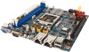
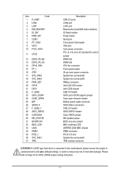
... port Reset button (top)/NMI button (bottom) ID Switch button Power button Serial port Front panel VGA header VGA port 4 pin power connector PCI-E x16 and x8 bandwidth switch jumper DIMM slot DIMM slot CPU fan connector Front panel header 24 pin main power connector System fan connector#2 System fan connector#3 PMBus connector Intel LGA1150 socket Intel C226 chipset USB 3.0 header SATA port 4 DOM support jumper Case open intrusion header Battery power cable connector SATA 6Gb/s connectors USB 2.0 header SATA SGPIO header Clear CMOS jumper ME Update jumper BIOS recovery jumper BMC readiness LED...
... port Reset button (top)/NMI button (bottom) ID Switch button Power button Serial port Front panel VGA header VGA port 4 pin power connector PCI-E x16 and x8 bandwidth switch jumper DIMM slot DIMM slot CPU fan connector Front panel header 24 pin main power connector System fan connector#2 System fan connector#3 PMBus connector Intel LGA1150 socket Intel C226 chipset USB 3.0 header SATA port 4 DOM support jumper Case open intrusion header Battery power cable connector SATA 6Gb/s connectors USB 2.0 header SATA SGPIO header Clear CMOS jumper ME Update jumper BIOS recovery jumper BMC readiness LED...
Manual
Page 9
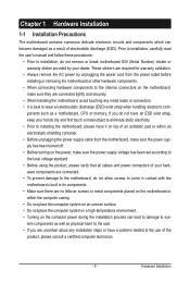
... not remove or break motherboard S/N (Serial Number) sticker or warranty sticker provided by unplugging the power cord from the power outlet before installing or removing the motherboard or other hardware components. • When connecting hardware components to the internal connectors on the motherboard, make sure the power supply voltage has been set according to the local voltage standard. • Before using the product, please verify that all cables and power connectors...
... not remove or break motherboard S/N (Serial Number) sticker or warranty sticker provided by unplugging the power cord from the power outlet before installing or removing the motherboard or other hardware components. • When connecting hardware components to the internal connectors on the motherboard, make sure the power supply voltage has been set according to the local voltage standard. • Before using the product, please verify that all cables and power connectors...
Manual
Page 10
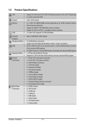
...174; 2300 chipset 5 x SATA 6Gb/s connectors Support for Intel IRSTe SATA RAID 0, RAID 1, RAID 10, RAID 5 Up to 4 USB 2.0 ports (2 on the back panel, 2 via the USB brackets connected to the internal USB headers) 2 x USB 3.0 ports ( 2 via the USB brackets connected to the internal USB headers) 1 x PCIe x16 slot (Gen3 x16 bus) Supports 2 x PCIe x8 slots (Gen3 x8 bus) via riser card and CFG5 jumper 1 x 24-pin ATX main power connector 1 x 4-pin ATX 12V power connector 5 x SATA 6Gb/s connectors 1 x CPU fan header 3 x System fan header 1 x Front panel header 1 x PMBus header 1 x Front USB 3.0 header...
...174; 2300 chipset 5 x SATA 6Gb/s connectors Support for Intel IRSTe SATA RAID 0, RAID 1, RAID 10, RAID 5 Up to 4 USB 2.0 ports (2 on the back panel, 2 via the USB brackets connected to the internal USB headers) 2 x USB 3.0 ports ( 2 via the USB brackets connected to the internal USB headers) 1 x PCIe x16 slot (Gen3 x16 bus) Supports 2 x PCIe x8 slots (Gen3 x8 bus) via riser card and CFG5 jumper 1 x 24-pin ATX main power connector 1 x 4-pin ATX 12V power connector 5 x SATA 6Gb/s connectors 1 x CPU fan header 3 x System fan header 1 x Front panel header 1 x PMBus header 1 x Front USB 3.0 header...

Manual
Page 15
... the same capacity, brand, speed, and chips be installed in Dual Channel mode. 1. Enabling Dual Channel memory mode will automatically detect the specifications and capacity of the memory. Dual Channel mode cannot be used . • Always turn off the computer and unplug the power cord from the power outlet before installing the memory to insert the memory, switch the direction. 1-4-1 Dual Channel Memory Configuration This motherboard provides two DDR3 memory sockets and supports Dual Channel Technology. tion. DDR3_P0_A0 DDR3_P0_B0 Due to CPU limitations, read the following...
... the same capacity, brand, speed, and chips be installed in Dual Channel mode. 1. Enabling Dual Channel memory mode will automatically detect the specifications and capacity of the memory. Dual Channel mode cannot be used . • Always turn off the computer and unplug the power cord from the power outlet before installing the memory to insert the memory, switch the direction. 1-4-1 Dual Channel Memory Configuration This motherboard provides two DDR3 memory sockets and supports Dual Channel Technology. tion. DDR3_P0_A0 DDR3_P0_B0 Due to CPU limitations, read the following...
Manual
Page 16
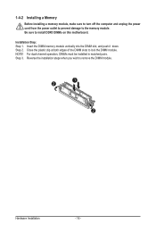
... DIMM slot, and push it down. For dual-channel operation, DIMMs must be installed in matched pairs. Installation Step: Step 1. Reverse the installation steps when you wish to install DDR3 DIMMs on this motherboard. Be sure to remove the DIMM module. 1 2 2 Hardware Installation - 16 - NOTE! 1-4-2 Installing a Memory Before installing a memory module, make sure to turn off the computer and unplug the power cord from the power outlet...
... DIMM slot, and push it down. For dual-channel operation, DIMMs must be installed in matched pairs. Installation Step: Step 1. Reverse the installation steps when you wish to install DDR3 DIMMs on this motherboard. Be sure to remove the DIMM module. 1 2 2 Hardware Installation - 16 - NOTE! 1-4-2 Installing a Memory Before installing a memory module, make sure to turn off the computer and unplug the power cord from the power outlet...

Manual
Page 17
... Panel Connectors VGA Port The video in port allows connect to video in ACPI S5 state (power off) System is powered on the system. Power Button and LED Press this button to reset the system. The following describes the states of the LAN port LEDs. Use this button to hard reset and power on . Color Status Description Blue On Unit selected for USB devices such as a USB keyboard/mouse, USB printer, USB flash drive and etc. - 17 - N/A Off No identification. Reset Button Press this port...
... Panel Connectors VGA Port The video in port allows connect to video in ACPI S5 state (power off) System is powered on the system. Power Button and LED Press this button to reset the system. The following describes the states of the LAN port LEDs. Use this button to hard reset and power on . Color Status Description Blue On Unit selected for USB devices such as a USB keyboard/mouse, USB printer, USB flash drive and etc. - 17 - N/A Off No identification. Reset Button Press this port...
Manual
Page 21
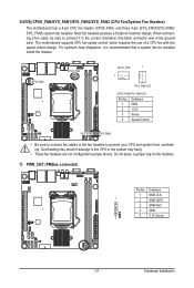
...(the black connector wire is recommended that a system fan be sure to connect it is the ground wire). Overheating may hang. • These fan headers are not configuration jumper blocks. When connecting a fan cable, be installed inside the chassis. 3/4/5/6) CPU0_FAN/SYS_FAN1/SYS_FAN2/SYS_FAN3 (CPU Fan/System Fan Headers) The motherboard has a 4-pin CPU fan header (CPU0_FAN), and three 4-pin (SYS_FAN1/SYS_FAN2/ SYS_FAN3) system fan headers. The motherboard supports CPU fan speed control, which requires the use of a CPU fan with fan speed control design. Hardware Installation For optimum...
...(the black connector wire is recommended that a system fan be sure to connect it is the ground wire). Overheating may hang. • These fan headers are not configuration jumper blocks. When connecting a fan cable, be installed inside the chassis. 3/4/5/6) CPU0_FAN/SYS_FAN1/SYS_FAN2/SYS_FAN3 (CPU Fan/System Fan Headers) The motherboard has a 4-pin CPU fan header (CPU0_FAN), and three 4-pin (SYS_FAN1/SYS_FAN2/ SYS_FAN3) system fan headers. The motherboard supports CPU fan speed control, which requires the use of a CPU fan with fan speed control design. Hardware Installation For optimum...

Manual
Page 31
... BIOS version, it with caution. To access the BIOS Setup program, press the key during system startup, saving system parameters and loading operating system, etc. Inadequately altering the settings may result in the CMOS. If this occurs, try to clear the CMOS values and reset the board to default values. (Refer to the Exit section in this chapter or introductions of the battery/clearing CMOS jumper in system's failure...
... BIOS version, it with caution. To access the BIOS Setup program, press the key during system startup, saving system parameters and loading operating system, etc. Inadequately altering the settings may result in the CMOS. If this occurs, try to clear the CMOS values and reset the board to default values. (Refer to the Exit section in this chapter or introductions of the battery/clearing CMOS jumper in system's failure...
Manual
Page 38
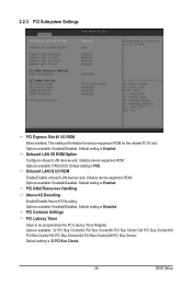
...: 32 PCI Bus Clocks/64 PCI Bus Clocks/96 PCI Bus Clocks/128 PCI Bus Clocks/160 PCI Bus Clocks/192 PCI Bus Clocks/224 PCI Bus Clocks/248 PCI Bus Clocks/. Default setting is Enabled. BIOS Setup Options available: PXE/iSCSI. PCI 64bit Resources Handling Above 4G Decoding Enable/Disable Above 4G Decoding. Default setting is 32 PCI Bus Clocks. - 38 - Options available: Enabled/Disabled. 2-2-3 PCI Subsystem Settings PCI Express Slot #1 I /O ROM Enable/Disable onboard LAN devices and initialize device expansion ROM. Onboard LAN I/O ROM Option Configure onboard LAN devices and...
...: 32 PCI Bus Clocks/64 PCI Bus Clocks/96 PCI Bus Clocks/128 PCI Bus Clocks/160 PCI Bus Clocks/192 PCI Bus Clocks/224 PCI Bus Clocks/248 PCI Bus Clocks/. Default setting is Enabled. BIOS Setup Options available: PXE/iSCSI. PCI 64bit Resources Handling Above 4G Decoding Enable/Disable Above 4G Decoding. Default setting is 32 PCI Bus Clocks. - 38 - Options available: Enabled/Disabled. 2-2-3 PCI Subsystem Settings PCI Express Slot #1 I /O ROM Enable/Disable onboard LAN devices and initialize device expansion ROM. Onboard LAN I/O ROM Option Configure onboard LAN devices and...

Manual
Page 40
...allow device to use 8-bit Tag field as a requester. Extended Synch Wnen this feature is Enabled. Default setting is enabled, the system will allow generation of Extended Synchronization patterns. Options available: Enabled/Disabled. No Snoop Enable/Disable PCI Express Device No Snoop option. BIOS Setup Options available: Enabled/Disabled. Maximum Playload Set maximum playload for PCI Express Device or allow system BIOS to select the value. Options available: Enabled/Disabled. Default setting is Disabled. Default setting is Disabled. Options available: Auto/128...
...allow device to use 8-bit Tag field as a requester. Extended Synch Wnen this feature is Enabled. Default setting is enabled, the system will allow generation of Extended Synchronization patterns. Options available: Enabled/Disabled. No Snoop Enable/Disable PCI Express Device No Snoop option. BIOS Setup Options available: Enabled/Disabled. Maximum Playload Set maximum playload for PCI Express Device or allow system BIOS to select the value. Options available: Enabled/Disabled. Default setting is Disabled. Default setting is Disabled. Options available: Auto/128...

Manual
Page 45
... disable the CPU C7 (ACPI C3) report. CPU C State Enable/Disable CPU C State feature. When enabled, the CPU core frequency and voltage will be changed by OS too if OS support it like Windows 2008 or newer Linux. Options available: Enabled/Disabled. Default setting is Disabled. CPU C7 Report (Note) Allows you to determine whether to improve its core. Default setting is Enabled. Options available: Enabled/Disabled. Default setting is Disabled. BIOS Setup - 45 - When this item is enabled, tje processor will automatically ramp up the clock speed...
... disable the CPU C7 (ACPI C3) report. CPU C State Enable/Disable CPU C State feature. When enabled, the CPU core frequency and voltage will be changed by OS too if OS support it like Windows 2008 or newer Linux. Options available: Enabled/Disabled. Default setting is Disabled. CPU C7 Report (Note) Allows you to determine whether to improve its core. Default setting is Enabled. Options available: Enabled/Disabled. Default setting is Disabled. BIOS Setup - 45 - When this item is enabled, tje processor will automatically ramp up the clock speed...
Manual
Page 48
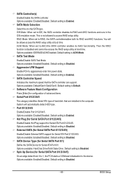
...: IDE/RAID/ACHI/Disabled. Hot Plug (for Serial SATA Port 0/1/2/3/4/5) Enable/Disable Hot Plug support for configuration of advanced items. Serial Port 0/1/2/3/4/5 The category identifies Serial ATA type of hard disk that the SATA controller can support. Options available: Enabled/Disabled. Default setting is ACHI Mode. Default setting is Disabled. SATA Controller Speed Indicates the maximum speed that are installed in the IDE emulation mode. SATA Controller(s) Enable/Disable the SATA controller. SATA Test Mode Enable/Disable SATA Test Mode. BIOS Setup Options...
...: IDE/RAID/ACHI/Disabled. Hot Plug (for Serial SATA Port 0/1/2/3/4/5) Enable/Disable Hot Plug support for configuration of advanced items. Serial Port 0/1/2/3/4/5 The category identifies Serial ATA type of hard disk that the SATA controller can support. Options available: Enabled/Disabled. Default setting is ACHI Mode. Default setting is Disabled. SATA Controller Speed Indicates the maximum speed that are installed in the IDE emulation mode. SATA Controller(s) Enable/Disable the SATA controller. SATA Test Mode Enable/Disable SATA Test Mode. BIOS Setup Options...
Manual
Page 52
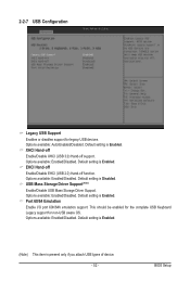
...USB Mass Storage Driver Support(Note) Enable/Disable USB Mass Storage Driver Support. Port 60/64 Emulation Enable I/O port 60h/64h emulation support. XHCI Hand-off Enable/Disable XHCI (USB 3.0) Hand-off function. Options available: Enabled/Disabled. Default setting is present only if you attach USB types of device. - 52 - Options available: Enabled/Disabled. BIOS Setup Options available: Enabled/Disabled. Options available: Auto/Enabled/Disabled. Default setting is Enabled. (Note) This item is Enabled. This should be enabled for the complete USB Keyboard Legacy support...
...USB Mass Storage Driver Support(Note) Enable/Disable USB Mass Storage Driver Support. Port 60/64 Emulation Enable I/O port 60h/64h emulation support. XHCI Hand-off Enable/Disable XHCI (USB 3.0) Hand-off function. Options available: Enabled/Disabled. Default setting is present only if you attach USB types of device. - 52 - Options available: Enabled/Disabled. BIOS Setup Options available: Enabled/Disabled. Options available: Auto/Enabled/Disabled. Default setting is Enabled. (Note) This item is Enabled. This should be enabled for the complete USB Keyboard Legacy support...
Manual
Page 57
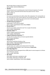
... signals. This is Disabled. (Note) Advanced items prompt when this mode enabled, only text will be sent to re-start bit indicates the beginning). Resolution 100x31 (Note) Enables or disables extended terminal resolution. Options available: VT100/LINUX/XTERMR6/SCO/ESCN/VT400. Options available: 80x24/80X25. Default setting is Enabled. SOL Switch When enabled, COM1 Switch to enable console redirection after O.S has loaded. BIOS Setup Flow Control Flow control can be send...
... signals. This is Disabled. (Note) Advanced items prompt when this mode enabled, only text will be sent to re-start bit indicates the beginning). Resolution 100x31 (Note) Enables or disables extended terminal resolution. Options available: VT100/LINUX/XTERMR6/SCO/ESCN/VT400. Options available: 80x24/80X25. Default setting is Enabled. SOL Switch When enabled, COM1 Switch to enable console redirection after O.S has loaded. BIOS Setup Flow Control Flow control can be send...
Manual
Page 61
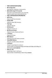
... status. Link Speed Change link speed duplex for the specified duration (up to input the desired value. Default setting is Auto Neg0tiated. Adapter PBA Display the Adapter PBA information. Bus:Device:Function Display the number of advanced items. Blink LEDs (range 0-15 seconds) Blink LEDs for current port. Virtual MAC Address Display the virtual MAC address information. Wake On LAN Enable/Disable Wake On LAN feature. BIOS Setup PCI Device ID Display the PCI device ID. PORT CONFIGURATION INFORMATION UEFI Driver Display the UEFI driver information.
... status. Link Speed Change link speed duplex for the specified duration (up to input the desired value. Default setting is Auto Neg0tiated. Adapter PBA Display the Adapter PBA information. Bus:Device:Function Display the number of advanced items. Blink LEDs (range 0-15 seconds) Blink LEDs for current port. Virtual MAC Address Display the virtual MAC address information. Wake On LAN Enable/Disable Wake On LAN feature. BIOS Setup PCI Device ID Display the PCI device ID. PORT CONFIGURATION INFORMATION UEFI Driver Display the UEFI driver information.

Manual
Page 64
BIOS Setup Default setting is Auto. - 64 - 2-3-1-1 Graphic Configuration Graphic Configuration Primary Display Device Configure the Primary display device. Options available: Auto/IGFX(if the CPU support graphic)/PEG/Onboard VGA.
BIOS Setup Default setting is Auto. - 64 - 2-3-1-1 Graphic Configuration Graphic Configuration Primary Display Device Configure the Primary display device. Options available: Auto/IGFX(if the CPU support graphic)/PEG/Onboard VGA.
Manual
Page 66
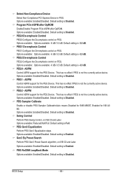
... active device. Swing Control Perform PEG Swing Control, on PEG. Default setting is Disabled. PEG0 - Default setting is Disabled. BIOS Setup - 66 - Options available: Enabled/Disabled. Default setting is Disabled. ASPM Control ASPM support for the PEG Device. Default setting is Disabled. Default setting is Disabled. Detect Non-Compliance Device Detect Non-Compliance PCI Express Device in PEG. Default setting is Enabled. Program PCIe ASPM after OpROM Enable/Disable Program PCIe ASPM after OpROM. Options available: Enabled/Disabled. Default setting is...
... active device. Swing Control Perform PEG Swing Control, on PEG. Default setting is Disabled. PEG0 - Default setting is Disabled. BIOS Setup - 66 - Options available: Enabled/Disabled. Default setting is Disabled. ASPM Control ASPM support for the PEG Device. Default setting is Disabled. Default setting is Disabled. Detect Non-Compliance Device Detect Non-Compliance PCI Express Device in PEG. Default setting is Enabled. Program PCIe ASPM after OpROM Enable/Disable Program PCIe ASPM after OpROM. Options available: Enabled/Disabled. Default setting is...
Manual
Page 74
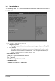
To enable or disable this field, a Administrator Password must first be set : • Administrator Password Entering this password will allow the user to access and change all settings in the Setup Utility. • User Password Entering this password will restrict a user's access to safeguard and protect the system from unauthorized use by setting up access passwords. Secure Boot menu Press [Enter] for configuration of passwords that you to the Setup menus. Administrator Password Press Enter to configure the user password. User Password Press Enter to configure the ...
To enable or disable this field, a Administrator Password must first be set : • Administrator Password Entering this password will allow the user to access and change all settings in the Setup Utility. • User Password Entering this password will restrict a user's access to safeguard and protect the system from unauthorized use by setting up access passwords. Secure Boot menu Press [Enter] for configuration of passwords that you to the Setup menus. Administrator Password Press Enter to configure the user password. User Password Press Enter to configure the ...
Manual
Page 87
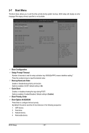
...87 - Boot Configuration Setup Prompt Timeout Number of seconds to wait for boot devices in the following secquence: 1. Options available: On/Off. Default setting is On. Hard drive. 3. Removable device. Press the numberic keys to configure the boot priority. Quiet Boot Enables or disables showing the logo during system boot-up. BIOS setup will display an error message if the legacy drive(s) specified is not bootable. Options available: Enabled/Disabled. UEFI device. 2. 2-7 Boot Menu The Boot menu allows you to set the drive priority during POST. Network device...
...87 - Boot Configuration Setup Prompt Timeout Number of seconds to wait for boot devices in the following secquence: 1. Options available: On/Off. Default setting is On. Hard drive. 3. Removable device. Press the numberic keys to configure the boot priority. Quiet Boot Enables or disables showing the logo during system boot-up. BIOS setup will display an error message if the legacy drive(s) specified is not bootable. Options available: Enabled/Disabled. UEFI device. 2. 2-7 Boot Menu The Boot menu allows you to set the drive priority during POST. Network device...


