
User Manual
Page 4
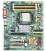
...isolate the screw from the system. 5. If you do not become alarmed you may be careful of your hands). Ensure that the ATX power supply is switched off , so be near the fixing hole, otherwise it may be a little hard to cut the bottom... you can still attach the motherboard to the mounting holes. Just cut off before handling computer components. English GA-3PXSL-RH Motherboard Item Checklist The GA-3PXSL-RH motherboard IDE (ATA100 ) cable x 1 / Floppy cable x 1 CD for motherboard driver & utility GA-3PXSL-RH user's manual Serial ATA cable x 4 I/O Shield Kit WARNING!
...isolate the screw from the system. 5. If you do not become alarmed you may be careful of your hands). Ensure that the ATX power supply is switched off , so be near the fixing hole, otherwise it may be a little hard to cut the bottom... you can still attach the motherboard to the mounting holes. Just cut off before handling computer components. English GA-3PXSL-RH Motherboard Item Checklist The GA-3PXSL-RH motherboard IDE (ATA100 ) cable x 1 / Floppy cable x 1 CD for motherboard driver & utility GA-3PXSL-RH user's manual Serial ATA cable x 4 I/O Shield Kit WARNING!
User Manual
Page 5
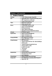
... Summary Form Factor CPU Chipset Memory I/O Control Expansion Slots On-Board SATA RAID On-Board Peripherals Hardware Monitor On-Board Graphic On-Board LAN 12" x 9.6" ATX size form factor, 4 layers PCB Supports AMD® OpteronTM 1000 series (Socket AM2) processor AMDTM Single/Dual Core in AM2 socket L2 cache on-die...
... Summary Form Factor CPU Chipset Memory I/O Control Expansion Slots On-Board SATA RAID On-Board Peripherals Hardware Monitor On-Board Graphic On-Board LAN 12" x 9.6" ATX size form factor, 4 layers PCB Supports AMD® OpteronTM 1000 series (Socket AM2) processor AMDTM Single/Dual Core in AM2 socket L2 cache on-die...
User Manual
Page 16
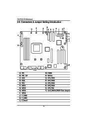
English GA-3PXSL-RH Motherboard 2-5: Connectors & Jumper Setting Introduction OP R S E D C H I GF Q A L T K J B N A) ATX B) ATX _12V C) IDE1 D) IDE2 E) FDD F) SATA1 G) SATA2 H) SATA3 I) SATA4 J) F_USB2 K) F_USB3 L) F_Panel1 M M) COMB N) Battery O) SYS_FAN1 P) SYS_FAN2 Q) SYS_FAN3 R) SYS_FAN4 S) CPU_FAN T) CLR_CMOS (CMOS Clear Jumper) 16
English GA-3PXSL-RH Motherboard 2-5: Connectors & Jumper Setting Introduction OP R S E D C H I GF Q A L T K J B N A) ATX B) ATX _12V C) IDE1 D) IDE2 E) FDD F) SATA1 G) SATA2 H) SATA3 I) SATA4 J) F_USB2 K) F_USB3 L) F_Panel1 M M) COMB N) Battery O) SYS_FAN1 P) SYS_FAN2 Q) SYS_FAN3 R) SYS_FAN4 S) CPU_FAN T) CLR_CMOS (CMOS Clear Jumper) 16

User Manual
Page 17
B ) ATX_12V( +12V Power Connector) Connector Introduction 24 12 1 13 PIN No. 1 2 3 4 5 6 7 8 9 10 11 12 13 14 15 16 17 18 19 20 21 22 23 24 Definition +3.3V +3.3V GND +5V GND +5V GND POK 5VSB +12V +12V +3.3V +3.3V -12V GND PSON GND GND GND -5V +5V +5V +5V GND Pin No. A) ATX (ATX Power Connector) AC power cord should only be connected to your power supply unit after ATX power cable and other related devices are firmly connected to the mainboard. Definition 1 1 GND 2 GND 3 12V 4 12V This connector (ATX +12V) is used only for CPU1 Core Voltage. 17
B ) ATX_12V( +12V Power Connector) Connector Introduction 24 12 1 13 PIN No. 1 2 3 4 5 6 7 8 9 10 11 12 13 14 15 16 17 18 19 20 21 22 23 24 Definition +3.3V +3.3V GND +5V GND +5V GND POK 5VSB +12V +12V +3.3V +3.3V -12V GND PSON GND GND GND -5V +5V +5V +5V GND Pin No. A) ATX (ATX Power Connector) AC power cord should only be connected to your power supply unit after ATX power cable and other related devices are firmly connected to the mainboard. Definition 1 1 GND 2 GND 3 12V 4 12V This connector (ATX +12V) is used only for CPU1 Core Voltage. 17
