User Guide
Page 1
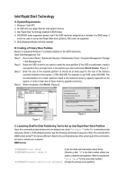
... computer. "X" is unallocated, create a new partition first), and right-click on the system. (1 GB=1024 MB. At the diskpart prompt, type the following commands in BIOS Setup 4. Refer to create the store partition. An SSD with SP1 2. Intel Rapid Start Technology A. Windows 7 with size larger than the total system memory 3. Open...
... computer. "X" is unallocated, create a new partition first), and right-click on the system. (1 GB=1024 MB. At the diskpart prompt, type the following commands in BIOS Setup 4. Refer to create the store partition. An SSD with SP1 2. Intel Rapid Start Technology A. Windows 7 with size larger than the total system memory 3. Open...
User Guide
Page 2
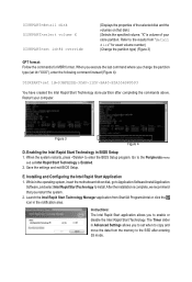
... click the icon in Advanced Settings allows you restart the system. 2. Go to the Peripherals menu and set Intel Rapid Start Technology to enter the BIOS Setup program. The Timer slider in the notification area. DISKPART>detail disk DISKPART>select volume X DISKPART>set id=84 override (Displays the properties of your... from "detail disk" for exact volume number) (Change the partition type) (Figure 3) GPT format: Follow the commands for MBR format. Save the settings and exit BIOS Setup. E. Installing and Configuring the Intel Rapid Start Application 1. While in...
... click the icon in Advanced Settings allows you restart the system. 2. Go to the Peripherals menu and set Intel Rapid Start Technology to enter the BIOS Setup program. The Timer slider in the notification area. DISKPART>detail disk DISKPART>select volume X DISKPART>set id=84 override (Displays the properties of your... from "detail disk" for exact volume number) (Change the partition type) (Figure 3) GPT format: Follow the commands for MBR format. Save the settings and exit BIOS Setup. E. Installing and Configuring the Intel Rapid Start Application 1. While in...
User Guide
Page 3
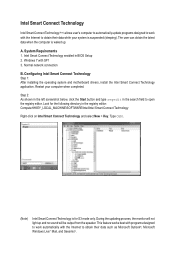
...®, Microsoft Windows Live™ Mail, and Seesmic®. The user can obtain the latest data when the computer is for the following directory in BIOS Setup 2. Intel Smart Connect Technology Intel Smart Connect Technology (Note) allows user's computer to automatically update programs designed to work automatically with the Internet to...
...®, Microsoft Windows Live™ Mail, and Seesmic®. The user can obtain the latest data when the computer is for the following directory in BIOS Setup 2. Intel Smart Connect Technology Intel Smart Connect Technology (Note) allows user's computer to automatically update programs designed to work automatically with the Internet to...
User Guide
Page 5
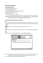
... SSD works as a cache of the motherboard driver disk to open the Intel Rapid Storage Technology utility. Configuring Intel Smart Response Technology Step 1: While in BIOS Setup 4.
... SSD works as a cache of the motherboard driver disk to open the Intel Rapid Storage Technology utility. Configuring Intel Smart Response Technology Step 1: While in BIOS Setup 4.
Manual
Page 3
... to their respective owners. For product-related information, check on our website at: http://www.gigabyte.com Identifying Your Motherboard Revision The revision number on your motherboard revision before updating motherboard BIOS, drivers, or when looking for technical information. Copyright © 2012 GIGA-BYTE TECHNOLOGY CO., LTD. All rights reserved. Example: Disclaimer...
... to their respective owners. For product-related information, check on our website at: http://www.gigabyte.com Identifying Your Motherboard Revision The revision number on your motherboard revision before updating motherboard BIOS, drivers, or when looking for technical information. Copyright © 2012 GIGA-BYTE TECHNOLOGY CO., LTD. All rights reserved. Example: Disclaimer...
Manual
Page 4
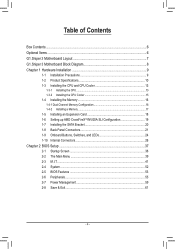
Table of Contents Box Contents...6 Optional Items...6 G1.Sniper 3 Motherboard Layout 7 G1.Sniper 3 Motherboard Block Diagram 8 Chapter 1 Hardware Installation 9 1-1 Installation Precautions 9 1-2 Product Specifications 10 1-3 Installing the CPU and CPU Cooler 13 1-3-1 ... SATA Bracket 20 1-8 Back Panel Connectors 21 1-9 Onboard Buttons, Switches, and LEDs 24 1-10 Internal Connectors 26 Chapter 2 BIOS Setup 37 2-1 Startup Screen 38 2-2 The Main Menu 39 2-3 M.I.T...41 2-4 System...52 2-5 BIOS Features 53 2-6 Peripherals...55 2-7 Power Management 59 2-8 Save & Exit...61 - 4 -
Table of Contents Box Contents...6 Optional Items...6 G1.Sniper 3 Motherboard Layout 7 G1.Sniper 3 Motherboard Block Diagram 8 Chapter 1 Hardware Installation 9 1-1 Installation Precautions 9 1-2 Product Specifications 10 1-3 Installing the CPU and CPU Cooler 13 1-3-1 ... SATA Bracket 20 1-8 Back Panel Connectors 21 1-9 Onboard Buttons, Switches, and LEDs 24 1-10 Internal Connectors 26 Chapter 2 BIOS Setup 37 2-1 Startup Screen 38 2-2 The Main Menu 39 2-3 M.I.T...41 2-4 System...52 2-5 BIOS Features 53 2-6 Peripherals...55 2-7 Power Management 59 2-8 Save & Exit...61 - 4 -
Manual
Page 5
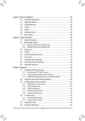
... 64 3-4 Contact...65 3-5 System...65 3-6 Download Center 66 3-7 New Program 66 Chapter 4 Unique Features 67 4-1 Xpress Recovery2 67 4-2 BIOS Update Utilities 70 4-2-1 Updating the BIOS with the Q-Flash Utility 70 4-2-2 Updating the BIOS with the @BIOS Utility 73 4-3 EasyTune 6...74 4-4 Q-Share...75 4-5 eXtreme Hard Drive (X.H.D 76 4-6 Auto Green...77 4-7 Intel Rapid Start Technology 78...
... 64 3-4 Contact...65 3-5 System...65 3-6 Download Center 66 3-7 New Program 66 Chapter 4 Unique Features 67 4-1 Xpress Recovery2 67 4-2 BIOS Update Utilities 70 4-2-1 Updating the BIOS with the Q-Flash Utility 70 4-2-2 Updating the BIOS with the @BIOS Utility 73 4-3 EasyTune 6...74 4-4 Q-Share...75 4-5 eXtreme Hard Drive (X.H.D 76 4-6 Auto Green...77 4-7 Intel Rapid Start Technology 78...
Manual
Page 8
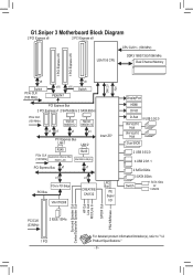
G1.Sniper 3 Motherboard Block Diagram 2 PCI Express x8 2 PCI Express x8 LGA1155 CPU CPU CLK+/- (100 MHz) DDR3 1600/1333/1066 MHz Dual Channel Memory 1 PCI Express ... PCI Bridge PCI Bus VIA VT6308 x1 CREATIVE CA0132 LPC Bus iTE Super I/O DisplayPort HDMI DVI-D D-Sub VIA VL810 Hub VIA VL810 Hub 8 USB 3.0/2.0 Dual BIOS 2 USB 3.0/2.0 4 USB 2.0/1.1 2 SATA 6Gb/s 3 SATA 3Gb/s Switch 1 SATA 3Gb/s or 1 mSATA Surround Speaker Out Center/Subwoofer Speaker Out HP Out Line Out MIC/Line In...
G1.Sniper 3 Motherboard Block Diagram 2 PCI Express x8 2 PCI Express x8 LGA1155 CPU CPU CLK+/- (100 MHz) DDR3 1600/1333/1066 MHz Dual Channel Memory 1 PCI Express ... PCI Bridge PCI Bus VIA VT6308 x1 CREATIVE CA0132 LPC Bus iTE Super I/O DisplayPort HDMI DVI-D D-Sub VIA VL810 Hub VIA VL810 Hub 8 USB 3.0/2.0 Dual BIOS 2 USB 3.0/2.0 4 USB 2.0/1.1 2 SATA 6Gb/s 3 SATA 3Gb/s Switch 1 SATA 3Gb/s or 1 mSATA Surround Speaker Out Center/Subwoofer Speaker Out HP Out Line Out MIC/Line In...
Manual
Page 11
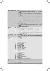
... header 1 x front panel audio header 2 x USB 2.0/1.1 headers 2 x USB 3.0/2.0 headers 2 x IEEE 1394a headers 1 x Clear CMOS jumper 1 x power button 1 x Clear CMOS button 1 x reset button Voltage measurement points 1 x BIOS switch 1 x Trusted Platform Module (TPM) header 1 x PS/2 keyboard/mouse port 6 x USB 3.0/2.0 ports 1 x D-Sub port - 11 - Storage Interface Š Š USB Š Š IEEE 1394 Š...
... header 1 x front panel audio header 2 x USB 2.0/1.1 headers 2 x USB 3.0/2.0 headers 2 x IEEE 1394a headers 1 x Clear CMOS jumper 1 x power button 1 x Clear CMOS button 1 x reset button Voltage measurement points 1 x BIOS switch 1 x Trusted Platform Module (TPM) header 1 x PS/2 keyboard/mouse port 6 x USB 3.0/2.0 ports 1 x D-Sub port - 11 - Storage Interface Š Š USB Š Š IEEE 1394 Š...
Manual
Page 12
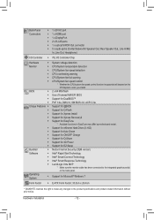
...GIGABYTE reserves the right to make any changes to the integrated graphics port(s) on the CPU/system cooler you install. 2 x 64 Mbit flash Use of licensed AMI EFI BIOS Support for DualBIOS™ PnP 1.0a, DMI 2.0, SM BIOS 2.6, ACPI 2.0a Support for @BIOS...prior notice. Back Panel Š Connectors Š Š Š Š Š I/O Controller Š Hardware Š Monitor Š Š Š Š Š BIOS Š Š Š Š Unique Features Š Š Š Š Š Š Š Š Š Š Š Bundled Š ...
...GIGABYTE reserves the right to make any changes to the integrated graphics port(s) on the CPU/system cooler you install. 2 x 64 Mbit flash Use of licensed AMI EFI BIOS Support for DualBIOS™ PnP 1.0a, DMI 2.0, SM BIOS 2.6, ACPI 2.0a Support for @BIOS...prior notice. Back Panel Š Connectors Š Š Š Š Š I/O Controller Š Hardware Š Monitor Š Š Š Š Š BIOS Š Š Š Š Unique Features Š Š Š Š Š Š Š Š Š Š Š Bundled Š ...
Manual
Page 16
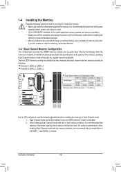
...begin to install the memory: • Make sure that memory of the same capacity, brand, speed, and chips be used . (Go to GIGABYTE's website for the latest supported memory speeds and memory modules.) • Always turn off the computer and unplug the power cord from the power ... mode with two or four memory modules, it is recommended that the motherboard supports the memory. Hardware Installation - 16 - It is installed, the BIOS will double the original memory bandwidth. A memory module can be used . The four DDR3 memory sockets are unable to prevent hardware damage. •...
...begin to install the memory: • Make sure that memory of the same capacity, brand, speed, and chips be used . (Go to GIGABYTE's website for the latest supported memory speeds and memory modules.) • Always turn off the computer and unplug the power cord from the power ... mode with two or four memory modules, it is recommended that the motherboard supports the memory. Hardware Installation - 16 - It is installed, the BIOS will double the original memory bandwidth. A memory module can be used . The four DDR3 memory sockets are unable to prevent hardware damage. •...
Manual
Page 18
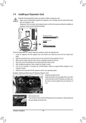
... the PCI Express slot to install an expansion card: • Make sure the motherboard supports the expansion card. If necessary, go to BIOS Setup to make any required BIOS changes for your expansion card. • Always turn off the computer and unplug the power cord from the power outlet before you begin...
... the PCI Express slot to install an expansion card: • Make sure the motherboard supports the expansion card. If necessary, go to BIOS Setup to make any required BIOS changes for your expansion card. • Always turn off the computer and unplug the power cord from the power outlet before you begin...
Manual
Page 22
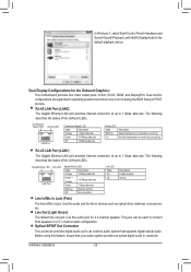
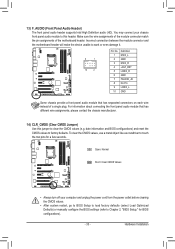
... Off Description Linked properly No link Line In/Mic In Jack (Pink) The line in/Mic in operating system environment only, but not during the BIOS Setup or POST process. Hardware Installation - 22 - The following describes the states of the LAN port LEDs. Line Out (Light Green) The default line out...
... Off Description Linked properly No link Line In/Mic In Jack (Pink) The line in/Mic in operating system environment only, but not during the BIOS Setup or POST process. Hardware Installation - 22 - The following describes the states of the LAN port LEDs. Line Out (Light Green) The default line out...
Manual
Page 24
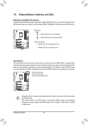
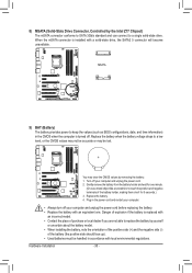
.... VVoollttaaggee mmeeaassuurreemmeenntt ppooiinnttss((GG11..SSnniippeerr 33)) BBIIOOSS SSwwiittcchheerr ((SSWW44)) 1-9 Onboard Buttons, Switches, and LEDs BIOS Switch and BIOS LED Indicators The BIOS switch (SW4) allows users to easily select a different BIOS for BIOS configurations). The LED indicator (MBIOS_LED/BBIOS_LED) shows which BIOS is active) Quick Buttons This motherboard has 3 quick buttons: power button, reset button and...
.... VVoollttaaggee mmeeaassuurreemmeenntt ppooiinnttss((GG11..SSnniippeerr 33)) BBIIOOSS SSwwiittcchheerr ((SSWW44)) 1-9 Onboard Buttons, Switches, and LEDs BIOS Switch and BIOS LED Indicators The BIOS switch (SW4) allows users to easily select a different BIOS for BIOS configurations). The LED indicator (MBIOS_LED/BBIOS_LED) shows which BIOS is active) Quick Buttons This motherboard has 3 quick buttons: power button, reset button and...
Manual
Page 25
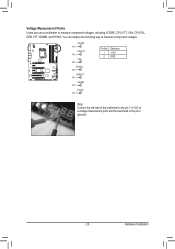
... DIP Pin 1 1 23 2 GND Voltage measurement points(G1.Sniper 3) VSA BIOS Switcher (SW4) PCIe power connector (SATA)(X58A-OC) Pin 1 Voltage measurement points(G1.Sniper 3) CPUPLL BIOS Switcher (SW4) Pin 1 Voltage measurement points(G1.Sniper 3) DDRVTT BIOS Switcher (SW4) Pin 1 Voltage measurement points(G1.Sniper 3) VDIMM BIOS Switcher (SW4) Pin 1 Voltage measurement points(G1.Sniper 3) PCHIO BIOS Switcher (SW4) Pin 1 M_SATA M_SATA M_SATA M_SATA M_SATA...
... DIP Pin 1 1 23 2 GND Voltage measurement points(G1.Sniper 3) VSA BIOS Switcher (SW4) PCIe power connector (SATA)(X58A-OC) Pin 1 Voltage measurement points(G1.Sniper 3) CPUPLL BIOS Switcher (SW4) Pin 1 Voltage measurement points(G1.Sniper 3) DDRVTT BIOS Switcher (SW4) Pin 1 Voltage measurement points(G1.Sniper 3) VDIMM BIOS Switcher (SW4) Pin 1 Voltage measurement points(G1.Sniper 3) PCHIO BIOS Switcher (SW4) Pin 1 M_SATA M_SATA M_SATA M_SATA M_SATA...
Manual
Page 28
... configuration jumper blocks. For optimum heat dissipation, it in damage to the onboard PCI Express x16 slots. Definition 1 NC BIOS Switcher (SW4) 2 NC 1 3 NC 4 GND 5 GND 15 6 GND 7 VCC Voltage measurement points(G1.Sniper 3) 8 VCC 9 VCC 10 GND 11 GND 12 GND 13 +12V 14 +12V 15 +12V F_AUDIO(H) F_USB30 TPM w/housing 4/5) CPU_FAN...
... configuration jumper blocks. For optimum heat dissipation, it in damage to the onboard PCI Express x16 slots. Definition 1 NC BIOS Switcher (SW4) 2 NC 1 3 NC 4 GND 5 GND 15 6 GND 7 VCC Voltage measurement points(G1.Sniper 3) 8 VCC 9 VCC 10 GND 11 GND 12 GND 13 +12V 14 +12V 15 +12V F_AUDIO(H) F_USB30 TPM w/housing 4/5) CPU_FAN...
Manual
Page 30
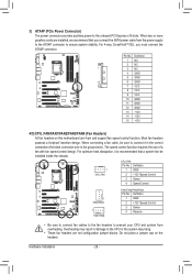
...mSATA connector is replaced with a solid-state drive, the SATA2 5 connector will become unavailable. MSATA PWM Switch (X58A-OC) BIOS Switcher (X58A-OC) 1 M_SATA F_PANEL(NH) BIOS Switcher (SW4) Voltage measurement points(G1.Sniper 3) DIP 1 23 PCIe power connector (SATA)(X58A-OC) DIP 1 23 1 DIP 1 23 1 DIP 1 23 ... be handled in accordance with an equivalent one minute. (Or use a metal object like a screwdriver to keep the values (such as BIOS configurations, date, and time information) in the power cord and restart your computer and unplug the power cord. 2. Turn off . Gently...
...mSATA connector is replaced with a solid-state drive, the SATA2 5 connector will become unavailable. MSATA PWM Switch (X58A-OC) BIOS Switcher (X58A-OC) 1 M_SATA F_PANEL(NH) BIOS Switcher (SW4) Voltage measurement points(G1.Sniper 3) DIP 1 23 PCIe power connector (SATA)(X58A-OC) DIP 1 23 1 DIP 1 23 1 DIP 1 23 ... be handled in accordance with an equivalent one minute. (Or use a metal object like a screwdriver to keep the values (such as BIOS configurations, date, and time information) in the power cord and restart your computer and unplug the power cord. 2. Turn off . Gently...
Manual
Page 32
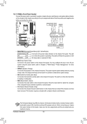
...): Connects to this header according to the power switch on the chassis front panel. When connecting your system using the power switch (refer to Chapter 2, "BIOS Setup," "Power Management," for more information). •• SPEAK (Speaker, Orange): Connects to the reset switch on the chassis front panel. The LED is operating...
...): Connects to this header according to the power switch on the chassis front panel. When connecting your system using the power switch (refer to Chapter 2, "BIOS Setup," "Power Management," for more information). •• SPEAK (Speaker, Orange): Connects to the reset switch on the chassis front panel. The LED is operating...
Manual
Page 33
...)r) ng Use this header. DIP 1 23 PCIe power connector (SATA)(X58A-OC) Open: Normal Short: Clear CMOS Values Voltage measurement points(G1.Sniper 3) BIOS Switcher (SW4) •• Always turn off your chassis front panel audio module to touch the two pins for... Definition audio (HD). Make sure the wire assignments of the module connector match the pin assignments of a single plug. WdaMteSwiintcfho(rXm58aAti-oOnC)and BIOS configurations) and reset the CMOS values to work or even damage it. Hardware Installation F_PANEL (H61M-D2) ACPI_CPT (GA-IVB) SMB_CPT (GA-IVB...
...)r) ng Use this header. DIP 1 23 PCIe power connector (SATA)(X58A-OC) Open: Normal Short: Clear CMOS Values Voltage measurement points(G1.Sniper 3) BIOS Switcher (SW4) •• Always turn off your chassis front panel audio module to touch the two pins for... Definition audio (HD). Make sure the wire assignments of the module connector match the pin assignments of a single plug. WdaMteSwiintcfho(rXm58aAti-oOnC)and BIOS configurations) and reset the CMOS values to work or even damage it. Hardware Installation F_PANEL (H61M-D2) ACPI_CPT (GA-IVB) SMB_CPT (GA-IVB...
Manual
Page 34
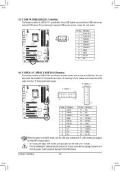
...6 USB DY+ 7 GND 8 GND 9 No Pin 10 NC F_USB30 16) F_USB30_1/F_USB30_2 (USB 3.0/2.0 Headers) The headers conform to the USB bracket. 1 DIP 1 23 1 Voltage measuremen BIOS Switcher (X 1 PCIe power conn PWM Switch (X DIP 1 23 1 23 1 Hardware Installation - 34 - TPM 12 D23 SSRX1+ w/housin1g3 GND 4 GND 14 SSTX2+ 5 SSTX16 SSTX1+ 15... can provide two USB ports via an UG T optional USB bracket. Definition Pin No. PCIe power connector (SATA)(X58A-OC) Voltage measurement points(G1.Sniper 3) BIO For purchasing the optional USB bracket, please contact the local dealer.
...6 USB DY+ 7 GND 8 GND 9 No Pin 10 NC F_USB30 16) F_USB30_1/F_USB30_2 (USB 3.0/2.0 Headers) The headers conform to the USB bracket. 1 DIP 1 23 1 Voltage measuremen BIOS Switcher (X 1 PCIe power conn PWM Switch (X DIP 1 23 1 23 1 Hardware Installation - 34 - TPM 12 D23 SSRX1+ w/housin1g3 GND 4 GND 14 SSTX2+ 5 SSTX16 SSTX1+ 15... can provide two USB ports via an UG T optional USB bracket. Definition Pin No. PCIe power connector (SATA)(X58A-OC) Voltage measurement points(G1.Sniper 3) BIO For purchasing the optional USB bracket, please contact the local dealer.


