User Manual
Page 4
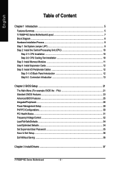
...Step 5: Install I/O Peripherals Cables 12 Step 5-1: I/O Back Panel Introduction 12 Step 5-2 : Connectors Introduction 13 Chapter 2 BIOS Setup 21 The Main Menu (For example: BIOS Ver. : F4c 21 Standard CMOS Features ...23 Advanced BIOS Features ...25 IntegratedPeripherals ...26 Power Management Setup ...28 PnP/PCI Configurations ...30 PCI Health Status ...31 Frequency/Voltage Control ...32 Load Fail-Safe Defaults ...34 Load Optimized Defaults ...34 Set Supervisor/User Password 35 Save & Exit Setup ...36 Exit Without Saving ...36 Chapter 3 Install Drivers 37 7VT600P-RZ Series Motherboard...
...Step 5: Install I/O Peripherals Cables 12 Step 5-1: I/O Back Panel Introduction 12 Step 5-2 : Connectors Introduction 13 Chapter 2 BIOS Setup 21 The Main Menu (For example: BIOS Ver. : F4c 21 Standard CMOS Features ...23 Advanced BIOS Features ...25 IntegratedPeripherals ...26 Power Management Setup ...28 PnP/PCI Configurations ...30 PCI Health Status ...31 Frequency/Voltage Control ...32 Load Fail-Safe Defaults ...34 Load Optimized Defaults ...34 Set Supervisor/User Password 35 Save & Exit Setup ...36 Exit Without Saving ...36 Chapter 3 Install Drivers 37 7VT600P-RZ Series Motherboard...

User Manual
Page 5
" * " Only for 7VT600P-RZ. - 5 - Introduction English Chapter 1 Introduction Features Summary CPU Chipset Memory Slots On-Board IDE Onboard SATA On-Board Floppy On-Board Peripherals On-Board LAN * On-Board Sound On-Board USB 2.0 On-Board SATA RAID y Socket A processor AMD AthlonTM/ AthlonTM XP/ DuronTM (K7) 128K L1 & 512K/256K/64K L2 cache on die 200/266/333/400 MHz FSB y Supports 1.4GHz and faster y North Bridge: VIA KT600 y Sourth Bridge: VIA VT8237 y 3 184-pin DDR sockets y Supports DDR DRAM PC2100...
" * " Only for 7VT600P-RZ. - 5 - Introduction English Chapter 1 Introduction Features Summary CPU Chipset Memory Slots On-Board IDE Onboard SATA On-Board Floppy On-Board Peripherals On-Board LAN * On-Board Sound On-Board USB 2.0 On-Board SATA RAID y Socket A processor AMD AthlonTM/ AthlonTM XP/ DuronTM (K7) 128K L1 & 512K/256K/64K L2 cache on die 200/266/333/400 MHz FSB y Supports 1.4GHz and faster y North Bridge: VIA KT600 y Sourth Bridge: VIA VT8237 y 3 184-pin DDR sockets y Supports DDR DRAM PC2100...

User Manual
Page 6
English BIOS I/O Control Hardware Monitor Additional Features Overclocking Form Factor y Licensed Award BIOS y Supports Q-Flash y IT8705 y CPU/System Fan Revolution detect y CPU/System temperature detect y System voltage detect y CPU/System fan fail warning y Thermal shutdown function y Supports @BIOS y Supports EasyTune y Over Voltage (CPU/AGP/DDR/PCI) by BIOS y Over Clock (CPU/AGP/DDR/PCI) by BIOS y 30.5cm x 20.0cm ATX size form factor, 4 layers PCB. 7VT600P-RZ Series Motherboard - 6 -
English BIOS I/O Control Hardware Monitor Additional Features Overclocking Form Factor y Licensed Award BIOS y Supports Q-Flash y IT8705 y CPU/System Fan Revolution detect y CPU/System temperature detect y System voltage detect y CPU/System fan fail warning y Thermal shutdown function y Supports @BIOS y Supports EasyTune y Over Voltage (CPU/AGP/DDR/PCI) by BIOS y Over Clock (CPU/AGP/DDR/PCI) by BIOS y 30.5cm x 20.0cm ATX size form factor, 4 layers PCB. 7VT600P-RZ Series Motherboard - 6 -
User Manual
Page 10
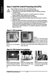
... heatsink and/or fan, resulting in the socket and look for CPU, chipset and most of the CPU. Never run under these specific bus frequencies are not the standard specifications for a (golden) cut edge well, it will depend on the center of the peripherals. Figure 2. Make sure the CPU fan is supported by the motherboard. 2. Figure 3. Whether your hardware configurations, including CPU, Memory, Cards...etc. Figure 2. Step 2-2: CPU Cooling Fan Installation...
... heatsink and/or fan, resulting in the socket and look for CPU, chipset and most of the CPU. Never run under these specific bus frequencies are not the standard specifications for a (golden) cut edge well, it will depend on the center of the peripherals. Figure 2. Make sure the CPU fan is supported by the motherboard. 2. Figure 3. Whether your hardware configurations, including CPU, Memory, Cards...etc. Figure 2. Step 2-2: CPU Cooling Fan Installation...

User Manual
Page 16
...) Please connect the power LED, PC speaker, reset switch and power switch etc. RESRES+ NC HD (IDE Hard Disk Active LED) SPK (Speaker Connector) RST (Reset Switch) PW (Soft Power Connector) MPD(Message LED/Power/ Sleep LED) NC Reset Switch IDE Hard Disk Active LED Pin 1: LED anode(+) Pin 2: LED cathode(-) Pin 1: VCC(+) Pin 2- Definition 1 1 MPD+ 2 MPD- 3 MPD- 7VT600P-RZ Series Motherboard - 16 - It will turn to another color. If you use dual color LED, power LED will blink when the system enters suspend mode. Message LED/ Speaker Connector Power/ Soft Power Sleep LED...
...) Please connect the power LED, PC speaker, reset switch and power switch etc. RESRES+ NC HD (IDE Hard Disk Active LED) SPK (Speaker Connector) RST (Reset Switch) PW (Soft Power Connector) MPD(Message LED/Power/ Sleep LED) NC Reset Switch IDE Hard Disk Active LED Pin 1: LED anode(+) Pin 2: LED cathode(-) Pin 1: VCC(+) Pin 2- Definition 1 1 MPD+ 2 MPD- 3 MPD- 7VT600P-RZ Series Motherboard - 16 - It will turn to another color. If you use dual color LED, power LED will blink when the system enters suspend mode. Message LED/ Speaker Connector Power/ Soft Power Sleep LED...

User Manual
Page 19
For optional F_USB cable, please contact your nearest dealer for optional game cables. Hardware Installation Process Definition 1 Signal 1 2 GND - 19 - Check the pin assignment while you connect the F_USB cable, incorrect connection between the cable and connector will make the device unable to enable or disable the "case open" item in BIOS if the system case begin remove. Check the pin assignment carefully while you connect the game cables. Definition Pin No. Definition...
For optional F_USB cable, please contact your nearest dealer for optional game cables. Hardware Installation Process Definition 1 Signal 1 2 GND - 19 - Check the pin assignment while you connect the F_USB cable, incorrect connection between the cable and connector will make the device unable to enable or disable the "case open" item in BIOS if the system case begin remove. Check the pin assignment carefully while you connect the game cables. Definition Pin No. Definition...

User Manual
Page 22
... is the System auto detect Temperature, voltage, fan, speed. • Frequency/Voltage Control This setup page is control CPU clock and frequency ratio. • Load Fail-Safe Defaults Fail-Safe Defaults indicates the value of the system parameters which the system would be in safe configuration. • Load Optimized Defaults Optimized Defaults indicates the value of the system parameters which the system would be in best performance configuration. • Set Supervisor Password Change, set , or disable password. It allows you...
... is the System auto detect Temperature, voltage, fan, speed. • Frequency/Voltage Control This setup page is control CPU clock and frequency ratio. • Load Fail-Safe Defaults Fail-Safe Defaults indicates the value of the system parameters which the system would be in safe configuration. • Load Optimized Defaults Optimized Defaults indicates the value of the system parameters which the system would be in best performance configuration. • Set Supervisor Password Change, set , or disable password. It allows you...

User Manual
Page 23
.... The hard disk will not work properly if you select User Type, related information will automatically detect HDD type. Day The day, from 1 to the following items. Enter the information directly from 1999 through 2098 Time The times format in the documentation form your drive must match with the drive table. English Standard CMOS Features CMOS Setup Utility-Copyright (C) 1984-2004 Award Software Standard CMOS Features Date...
.... The hard disk will not work properly if you select User Type, related information will automatically detect HDD type. Day The day, from 1 to the following items. Enter the information directly from 1999 through 2098 Time The times format in the documentation form your drive must match with the drive table. English Standard CMOS Features CMOS Setup Utility-Copyright (C) 1984-2004 Award Software Standard CMOS Features Date...

User Manual
Page 24
... base (or conventional) memory installed in the computer. All, But Keyboard The system boot will not stop for systems with 640K or more memory installed on The category determines whether the computer will determine the amount of memory located above 1 MB in the CPU's memory address map. 7VT600P-RZ Series Motherboard - 24 - The value of the BIOS. Floppy 3 Mode Support (for Japan Area) Disabled Normal Floppy Drive. (Default value) Drive A Drive A is typically 512K...
... base (or conventional) memory installed in the computer. All, But Keyboard The system boot will not stop for systems with 640K or more memory installed on The category determines whether the computer will determine the amount of memory located above 1 MB in the CPU's memory address map. 7VT600P-RZ Series Motherboard - 24 - The value of the BIOS. Floppy 3 Mode Support (for Japan Area) Disabled Normal Floppy Drive. (Default value) Drive A Drive A is typically 512K...

User Manual
Page 26
...Disabled Disable onboard 2nd channel IDE port. VIA Onboard LAN * Enabled Enable VIA Onboard LAN function. (Default value) Disabled Disable this option if you to use the onboard secondary PCI IDE. English Integrated Peripherals CMOS Setup Utility-Copyright (C) 1984-2004 Award Software Integrated Peripherals OnChip IDE Channel0 OnChip IDE Channel1 OnChip Serial ATA AC97 Audio VIA Onboard LAN * USB 1.1 Controller USB 2.0 Controller USB Keyboard Support USB Mouse Support VIA LAN Boot ROM * Onboard Serial Port 1 Onboard Serial Port 2 Onboard Parallel Port Parallel Port Mode Game Port...
...Disabled Disable onboard 2nd channel IDE port. VIA Onboard LAN * Enabled Enable VIA Onboard LAN function. (Default value) Disabled Disable this option if you to use the onboard secondary PCI IDE. English Integrated Peripherals CMOS Setup Utility-Copyright (C) 1984-2004 Award Software Integrated Peripherals OnChip IDE Channel0 OnChip IDE Channel1 OnChip Serial ATA AC97 Audio VIA Onboard LAN * USB 1.1 Controller USB 2.0 Controller USB Keyboard Support USB Mouse Support VIA LAN Boot ROM * Onboard Serial Port 1 Onboard Serial Port 2 Onboard Parallel Port Parallel Port Mode Game Port...
User Manual
Page 27
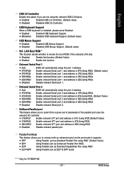
... the boot ROM of parameters if the parallel port uses the onboard I/O controller. 378/IRQ7 Enable onboard LPT port and address is 378, Using IRQ7.(Default Value) 278/IRQ5 Enable onboard LPT port and address is 278,Using IRQ5. 3BC/IRQ7 Enable onboard LPT port and address is 3BC,Using IRQ7. ECP+EPP Using Parallel port as ECP & EPP mode. Enabled Enabled USB 2.0 Controller. (Default value) Disabled Disabled USB 2.0 Controller. USB Keyboard Support When a USB keyboard is installed, please set of the onboard LAN chip. English USB 2.0 Controller Disable this function...
... the boot ROM of parameters if the parallel port uses the onboard I/O controller. 378/IRQ7 Enable onboard LPT port and address is 378, Using IRQ7.(Default Value) 278/IRQ5 Enable onboard LPT port and address is 278,Using IRQ5. 3BC/IRQ7 Enable onboard LPT port and address is 3BC,Using IRQ7. ECP+EPP Using Parallel port as ECP & EPP mode. Enabled Enabled USB 2.0 Controller. (Default value) Disabled Disabled USB 2.0 Controller. USB Keyboard Support When a USB keyboard is installed, please set of the onboard LAN chip. English USB 2.0 Controller Disable this function...

User Manual
Page 28
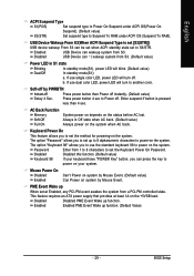
.... English Game Port Address Disabled Disabled this function. 300 Set Midi Port Address to 300. 330 Set Midi Port Address to 330. (Default Value) Midi Port IRQ 5 Set 5 for Midi Port IRQ. 10 Set 10 for Midi Port IRQ.(Default value) Power Management Setup CMOS Setup Utility-Copyright (C) 1984-2004 Award Software Power Management Setup ACPI Suspend Type x USB Device Wake-Up From S3 Power LED in S1 state Soft-Off by PWRBTN AC Back Function Keyboard Power On Mouse Power On PME...
.... English Game Port Address Disabled Disabled this function. 300 Set Midi Port Address to 300. 330 Set Midi Port Address to 330. (Default Value) Midi Port IRQ 5 Set 5 for Midi Port IRQ. 10 Set 10 for Midi Port IRQ.(Default value) Power Management Setup CMOS Setup Utility-Copyright (C) 1984-2004 Award Software Power Management Setup ACPI Suspend Type x USB Device Wake-Up From S3 Power LED in S1 state Soft-Off by PWRBTN AC Back Function Keyboard Power On Mouse Power On PME...
User Manual
Page 29
... to set up When set the Keyboard Power On Password. Enabled USB Device can press the key to set at least 1A on your system. The option "Password" allows you can wakeup system from 1 to 8 characters to power on the +5VSB lead. USB Device Wakeup From S3(When ACPI Suspend Type is pressed less than 4 sec. If use dual color LED, power LED will blink. (Default value) Dual/Off In standby mode(S1): a. Password Enter from S3. BIOS Setup
... to set up When set the Keyboard Power On Password. Enabled USB Device can press the key to set at least 1A on your system. The option "Password" allows you can wakeup system from 1 to 8 characters to power on the +5VSB lead. USB Device Wakeup From S3(When ACPI Suspend Type is pressed less than 4 sec. If use dual color LED, power LED will blink. (Default value) Dual/Off In standby mode(S1): a. Password Enter from S3. BIOS Setup

User Manual
Page 30
... You can enable wake on system. Disabled Disable this function. (Default Value) Enabled Enable alarm function to power on LAN feature by the "ModemRingOn/WakeOnLAN" or "PME Event Wake up ". Only enabled the feature by "PME Event Wake up " when the M/B has "WOL" onboard connector. Date (of Month) Alarm : Everyday, 1~31 Time (hh: mm: ss) Alarm : (0~23) : (0~59) : (0~59) PnP/PCI Configurations CMOS Setup Utility-Copyright (C) 1984-2004 Award Software PnP/PCI Configurations PCI1...
... You can enable wake on system. Disabled Disable this function. (Default Value) Enabled Enable alarm function to power on LAN feature by the "ModemRingOn/WakeOnLAN" or "PME Event Wake up ". Only enabled the feature by "PME Event Wake up " when the M/B has "WOL" onboard connector. Date (of Month) Alarm : Everyday, 1~31 Time (hh: mm: ss) Alarm : (0~23) : (0~59) : (0~59) PnP/PCI Configurations CMOS Setup Utility-Copyright (C) 1984-2004 Award Software PnP/PCI Configurations PCI1...

User Manual
Page 31
.... PCI Health Status CMOS Setup Utility-Copyright (C) 1984-2004 Award Software PC Health Status Reset Case Open Status Case Opened Vcore [Disabled] No 1.810V Item Help Menu Level X DDR Vtt +3.3V +12V Current System Temperature Current CPU Temperature Current CPU FAN Speed Current SYSTEM FAN Speed CPU FAN Fail Warning 1.248V 3.280V 11.968V 27oC 37oC 4687 RPM 0 RPM [Disabled] [Disabled] Don't reset case open status [Enabled] Clear case open status at next boot SYSTEM FAN Fail Warning [Disabled] KLJI: Move Enter...
.... PCI Health Status CMOS Setup Utility-Copyright (C) 1984-2004 Award Software PC Health Status Reset Case Open Status Case Opened Vcore [Disabled] No 1.810V Item Help Menu Level X DDR Vtt +3.3V +12V Current System Temperature Current CPU Temperature Current CPU FAN Speed Current SYSTEM FAN Speed CPU FAN Fail Warning 1.248V 3.280V 11.968V 27oC 37oC 4687 RPM 0 RPM [Disabled] [Disabled] Don't reset case open status [Enabled] Clear case open status at next boot SYSTEM FAN Fail Warning [Disabled] KLJI: Move Enter...

User Manual
Page 32
...have been opened, "Case Opened" will show "No". Fan Fail Warning (CPU / SYSTEM) Disabled Don't monitor current fan speed. (Default value) Enabled Alarm when stops. Frequency/Voltage Control CMOS Setup Utility-Copyright (C) 1984-2004 Award Software Frequency/Voltage Control Spread Spectrum Modulated CPU Host Clock Control ÚCPU Host Frequency(MHz) ÚPCI/AGP Frequency(MHz) DRAM Clock(MHz) CPU OverVoltage Control AGP OverVoltage Control DIMM OverVoltage Control [Enabled] [Disable] 133 33/66 [Auto] [Auto] [Auto] [Auto] Item Help Menu Level X KLJI: Move Enter: Select F5...
...have been opened, "Case Opened" will show "No". Fan Fail Warning (CPU / SYSTEM) Disabled Don't monitor current fan speed. (Default value) Enabled Alarm when stops. Frequency/Voltage Control CMOS Setup Utility-Copyright (C) 1984-2004 Award Software Frequency/Voltage Control Spread Spectrum Modulated CPU Host Clock Control ÚCPU Host Frequency(MHz) ÚPCI/AGP Frequency(MHz) DRAM Clock(MHz) CPU OverVoltage Control AGP OverVoltage Control DIMM OverVoltage Control [Enabled] [Disable] 133 33/66 [Auto] [Auto] [Auto] [Auto] Item Help Menu Level X KLJI: Move Enter: Select F5...

User Manual
Page 33
... "200-DDR400". Auto Supply voltage as user selected. If you use only! Incorrect using it may damage to 200MHz~254MHz. English Spread Spectrum Modulated Disabled Disable clock spread spectrum. Enabled Enable clock spread spectrum.(Default value) CPU Host Clock Control Note: If system hangs up before enter CMOS setup utility, wait for 20 sec for Over_Clock. When time out occur, system will reset and run at CPU default Host clock at next boot. PCI/AGP Frequency (MHz...
... "200-DDR400". Auto Supply voltage as user selected. If you use only! Incorrect using it may damage to 200MHz~254MHz. English Spread Spectrum Modulated Disabled Disable clock spread spectrum. Enabled Enable clock spread spectrum.(Default value) CPU Host Clock Control Note: If system hangs up before enter CMOS setup utility, wait for 20 sec for Over_Clock. When time out occur, system will reset and run at CPU default Host clock at next boot. PCI/AGP Frequency (MHz...
User Manual
Page 35
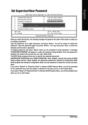
... enter Setup freely. A message "PASSWORD DISABLED" will appear to confirm the password. Type the password again and press . When disabled, anyone may also press to eight characters, and press . English Set Supervisor/User Password CMOS Setup Utility-Copyright (C) 1984-2004 Award Software ` Standard CMOS Features ` Advanced BIOS Features ` Integrated Peripherals ` Power Management Setup ` PnP/PCI ConfiguratiEonntser Password: ` PC Health Status ` Frequency/Voltage Control ESC: Quit F8: Q-Flash Load Fail-Safe Defaults Load Optimized Defaults Set Supervisor Password Set User...
... enter Setup freely. A message "PASSWORD DISABLED" will appear to confirm the password. Type the password again and press . When disabled, anyone may also press to eight characters, and press . English Set Supervisor/User Password CMOS Setup Utility-Copyright (C) 1984-2004 Award Software ` Standard CMOS Features ` Advanced BIOS Features ` Integrated Peripherals ` Power Management Setup ` PnP/PCI ConfiguratiEonntser Password: ` PC Health Status ` Frequency/Voltage Control ESC: Quit F8: Q-Flash Load Fail-Safe Defaults Load Optimized Defaults Set Supervisor Password Set User...

User Manual
Page 36
... Saving ` Frequency/Voltage Control ESC: Quit KLJI: Select Item F8: Q-Flash F10: Save & Exit Setup Abandon all Data Type "Y" will quit the Setup Utility without saving to Setup Utility. 7VT600P-RZ Series Motherboard - 36 - Type "N" will return to RTC CMOS. English Save & Exit Setup CMOS Setup Utility-Copyright (C) 1984-2004 Award Software ` Standard CMOS Features Load Fail-Safe Defaults ` Advanced BIOS Features Load Optimized Defaults ` Integrated Peripherals Set Supervisor Password ` Power Management Setup Set User Password ` PnP/PCI Configurations Save to CMOS and...
... Saving ` Frequency/Voltage Control ESC: Quit KLJI: Select Item F8: Q-Flash F10: Save & Exit Setup Abandon all Data Type "Y" will quit the Setup Utility without saving to Setup Utility. 7VT600P-RZ Series Motherboard - 36 - Type "N" will return to RTC CMOS. English Save & Exit Setup CMOS Setup Utility-Copyright (C) 1984-2004 Award Software ` Standard CMOS Features Load Fail-Safe Defaults ` Advanced BIOS Features Load Optimized Defaults ` Integrated Peripherals Set Supervisor Password ` Power Management Setup Set User Password ` PnP/PCI Configurations Save to CMOS and...

User Manual
Page 38
... chipset „ VIA 8237 Serial ATA Driver For VIA VT8237 Serial ATA driver. „ VIA USB 2.0 Controller USB 2.0 Driver information for XP For USB2.0 driver support under "Device Manager". English Driver install finished ! Item Description „ VIA 4IN1 Driver For INF, AGP, IDE and DMA Driver „ USB Path for 7VT600P-RZ. 7VT600P-RZ Series Motherboard - 38 - You have to resolve the USB device wake up S3 hang up issue in "Universal Serial Bus controller" under Windows XP operating system, please use Windows Service...
... chipset „ VIA 8237 Serial ATA Driver For VIA VT8237 Serial ATA driver. „ VIA USB 2.0 Controller USB 2.0 Driver information for XP For USB2.0 driver support under "Device Manager". English Driver install finished ! Item Description „ VIA 4IN1 Driver For INF, AGP, IDE and DMA Driver „ USB Path for 7VT600P-RZ. 7VT600P-RZ Series Motherboard - 38 - You have to resolve the USB device wake up S3 hang up issue in "Universal Serial Bus controller" under Windows XP operating system, please use Windows Service...


