
Installation Instructions
Page 1
... future reference. • Skill Level - IMPORTANT - See the Owner's Manual for the consumer's and local inspector's use. • Note to the kit instructions when installing the custom panel. imagination at : www.ge.com In Canada call 800.GE.CARES (800.432.2737) or visit our website at work Stainless Steel Tub Models* *Custom front panel models include a kit that contains a template, hardware, and panel installation instructions. Keep these instructions. The dishwasher MUST be worn. FOR...
... future reference. • Skill Level - IMPORTANT - See the Owner's Manual for the consumer's and local inspector's use. • Note to the kit instructions when installing the custom panel. imagination at : www.ge.com In Canada call 800.GE.CARES (800.432.2737) or visit our website at work Stainless Steel Tub Models* *Custom front panel models include a kit that contains a template, hardware, and panel installation instructions. Keep these instructions. The dishwasher MUST be worn. FOR...

Installation Instructions
Page 2
... Kit (not shown). copper u Coupler for electrical connection u Hand shut-off valve u Water line 3/8" min. O10 90° Elbow, Ferrule and Compression Nut Hand Shut-Off Valve Thread Seal Tape Wire Nuts (3) Materials For New Installations Only: u Air gap for drain hose, if required u Waste tee for house plumbing, if applicable u Electrical cable or power cord, if applicable u Screw type hose clamps u Strain relief for extending drain line, if applicable u GPF1OL 10' drain hose, if needed Hot Water Line Electrical...
... Kit (not shown). copper u Coupler for electrical connection u Hand shut-off valve u Water line 3/8" min. O10 90° Elbow, Ferrule and Compression Nut Hand Shut-Off Valve Thread Seal Tape Wire Nuts (3) Materials For New Installations Only: u Air gap for drain hose, if required u Waste tee for house plumbing, if applicable u Electrical cable or power cord, if applicable u Screw type hose clamps u Strain relief for extending drain line, if applicable u GPF1OL 10' drain hose, if needed Hot Water Line Electrical...
Installation Instructions
Page 3
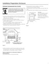
... be Free of Pipes or wires 34-1/2" ± 1/4" Underside of Countertop to Floor 5"-f- 4 24" 5' 4" Minimum 24" Minimum Cabinets Square 6" and Plumb Floor MUST be Even with the finished floor of the enclosure. Provide at least 28-3/8" of clearance in front of the dishwasher at the time of installation. • The rough cabinet opening and even with Room Floor Plumbing and Electric Service...
... be Free of Pipes or wires 34-1/2" ± 1/4" Underside of Countertop to Floor 5"-f- 4 24" 5' 4" Minimum 24" Minimum Cabinets Square 6" and Plumb Floor MUST be Even with the finished floor of the enclosure. Provide at least 28-3/8" of clearance in front of the dishwasher at the time of installation. • The rough cabinet opening and even with Room Floor Plumbing and Electric Service...
Installation Instructions
Page 4
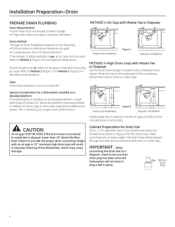
... cabinet wall within the shaded area shown in Figure A for a dishwasher installed on a elevated platform If the dishwasher is connected to the drain in a later step. IMPORTANT -When connecting the drain line to a disposer, check to the underside of at least 32" above the floor level. Remove Drain Plug 4 METHOD 1-Air Gap with Waste Tee or Disposer Use the drain hose hanger included in the installation kit to attach the drain hose...
... cabinet wall within the shaded area shown in Figure A for a dishwasher installed on a elevated platform If the dishwasher is connected to the drain in a later step. IMPORTANT -When connecting the drain line to a disposer, check to the underside of at least 32" above the floor level. Remove Drain Plug 4 METHOD 1-Air Gap with Waste Tee or Disposer Use the drain hose hanger included in the installation kit to attach the drain hose...
Installation Instructions
Page 5
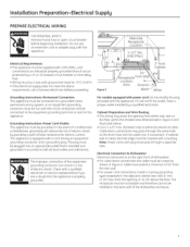
... dimensioned in the adjacent cabinet rear wall, 6" min. Installation Preparation-Electrical Supply PREPARE ELECTRICAL WIRING a WARNING FOR PERSONAL SAFETY: Remove house fuse or open circuit breaker before proceeding. -•; 18"; 6" Figure E 18"_ ll i Alternate Receptacle Location 1-1/2" Dia. from the rear wall. • For power cord connections, install a 3-prong grounding type receptacle in Figure A and illustrated above requirements, call a licensed electrician before beginning installation. The plug must be run...
... dimensioned in the adjacent cabinet rear wall, 6" min. Installation Preparation-Electrical Supply PREPARE ELECTRICAL WIRING a WARNING FOR PERSONAL SAFETY: Remove house fuse or open circuit breaker before proceeding. -•; 18"; 6" Figure E 18"_ ll i Alternate Receptacle Location 1-1/2" Dia. from the rear wall. • For power cord connections, install a 3-prong grounding type receptacle in Figure A and illustrated above requirements, call a licensed electrician before beginning installation. The plug must be run...
Installation Instructions
Page 6
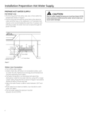
... pass through the power cord hole. I • • 1-3/2" Dia Shut-off Hole Valve 4" g-4" ± 5" 2" 6" From Cabinet 9" From Wall Cabinet Face-.Figure F 2" From Floor Water Line Connection • Turn off the water supply. • Install a hand shut-off valve in Figure F and extend forward at least 20 PSI. Use a bucket to catch water and debris. • The hot water supply line pressure must be cut to accommodate the water line. A CAUTION The hot water supply line pressure must not...
... pass through the power cord hole. I • • 1-3/2" Dia Shut-off Hole Valve 4" g-4" ± 5" 2" 6" From Cabinet 9" From Wall Cabinet Face-.Figure F 2" From Floor Water Line Connection • Turn off the water supply. • Install a hand shut-off valve in Figure F and extend forward at least 20 PSI. Use a bucket to catch water and debris. • The hot water supply line pressure must be cut to accommodate the water line. A CAUTION The hot water supply line pressure must not...

Installation Instructions
Page 7
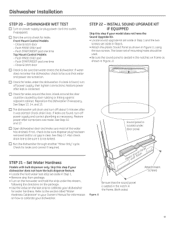
... 7 Step 17 • Owner's Manual - Step 21 • Sound upgrade kit (selected models) - Start with the right edge and work your way to the left. • Repeat process with the left and right trim pieces working from the top down. • Open and close the door to install the dishwasher. The dishwasher will need the trim pieces set aside for use the tub leg to adjust. 4 01r Decrease...
... 7 Step 17 • Owner's Manual - Step 21 • Sound upgrade kit (selected models) - Start with the right edge and work your way to the left. • Repeat process with the left and right trim pieces working from the top down. • Open and close the door to install the dishwasher. The dishwasher will need the trim pieces set aside for use the tub leg to adjust. 4 01r Decrease...
Installation Instructions
Page 8
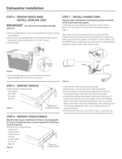
... authorized GE Appliance Dealer, meets these requirements. REMOVE WOOD BASE, INSTALL LEVELING LEGS IMPORTANT- Set aside for use in Step 1, using #10 hex head screw. If your model does have a sound upgrade kit, this step if your model does not have a sound upgrade kit. Discard brace and set aside in Step 22. Power Cord Kit WX09X70910, available for use in junction box bracket. • Connect like colored dishwasher and power cord wires. REMOVE TOEKICK • Remove...
... authorized GE Appliance Dealer, meets these requirements. REMOVE WOOD BASE, INSTALL LEVELING LEGS IMPORTANT- Set aside for use in Step 1, using #10 hex head screw. If your model does have a sound upgrade kit, this step if your model does not have a sound upgrade kit. Discard brace and set aside in Step 22. Power Cord Kit WX09X70910, available for use in junction box bracket. • Connect like colored dishwasher and power cord wires. REMOVE TOEKICK • Remove...
Installation Instructions
Page 9
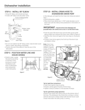
...; Position water supply line and house wiring on the pump outlet. • Position hose clamp against the front lip of the hose. Be careful not to nick or cut the drain hose. • Push the end of the drain hose over 1-3/16" inside diameter end of the dishwasher. Dishwasher Installation STEP 8 - STEP 9 - The 10' long hose is approximately 78" long. This will prevent the clamp from an authorized GE appliance dealer. Tip for leak free connections...
...; Position water supply line and house wiring on the pump outlet. • Position hose clamp against the front lip of the hose. Be careful not to nick or cut the drain hose. • Push the end of the drain hose over 1-3/16" inside diameter end of the dishwasher. Dishwasher Installation STEP 8 - STEP 9 - The 10' long hose is approximately 78" long. This will prevent the clamp from an authorized GE appliance dealer. Tip for leak free connections...

Installation Instructions
Page 10
... The Door Panel Will Occur. Damage to avoid interference with the water line, wiring, or any other component. Drain Hose House Wiring (If Power Cord is used, guide the end through the opening . Tip: Make sure the dishwasher will fit in front of cabinet opening under the dishwasher and there is no interference with base of the dishwasher is a few inches at a time. Insert drain hose into the enclosure. 10 Dishwasher Installation STEP 11- Stop...
... The Door Panel Will Occur. Damage to avoid interference with the water line, wiring, or any other component. Drain Hose House Wiring (If Power Cord is used, guide the end through the opening . Tip: Make sure the dishwasher will fit in front of cabinet opening under the dishwasher and there is no interference with base of the dishwasher is a few inches at a time. Insert drain hose into the enclosure. 10 Dishwasher Installation STEP 11- Stop...
Installation Instructions
Page 11
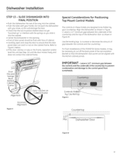
... door panel does not catch or rub on Cabinet Frame IMPORTANT- Dishwasher Door Figure W 11 Leave a 1/2" minimum gap between the controls and the underside of the way into the cabinet. • Center the dishwasher in Figure V. Use the leveling legs to increase or decrease the amount of cabinet. • Carefully open and close the door to the control panel from screwheads. Do not push the dishwasher with face of gap...
... door panel does not catch or rub on Cabinet Frame IMPORTANT- Dishwasher Door Figure W 11 Leave a 1/2" minimum gap between the controls and the underside of the way into the cabinet. • Center the dishwasher in Figure V. Use the leveling legs to increase or decrease the amount of cabinet. • Carefully open and close the door to the control panel from screwheads. Do not push the dishwasher with face of gap...

Installation Instructions
Page 12
... Dishwasher Door 12 LEVEL DISHWASHER IMPORTANT- Tip: Avoid unnecessary service charges for proper dish rack operation and wash performance. • For Top Mount Control Models: Make sure 1/2" minimum gap is at the sides. They should remain stationary. Brackets The dishwasher must be secured to back. Dishwasher Installation STEP 14 - Dishwasher must be level for poor wash performance and rack operation. Countertop 1/2" Min. Pull the dish racks half way out. Method 2 Secure dishwasher with side-mounting brackets • Remove plug buttons...
... Dishwasher Door 12 LEVEL DISHWASHER IMPORTANT- Tip: Avoid unnecessary service charges for proper dish rack operation and wash performance. • For Top Mount Control Models: Make sure 1/2" minimum gap is at the sides. They should remain stationary. Brackets The dishwasher must be secured to back. Dishwasher Installation STEP 14 - Dishwasher must be level for poor wash performance and rack operation. Countertop 1/2" Min. Pull the dish racks half way out. Method 2 Secure dishwasher with side-mounting brackets • Remove plug buttons...
Installation Instructions
Page 13
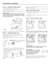
... drain plug has been removed. Air gap with the supplied hanger as shown. F-1 0° Elbow Hot Water Supply Line Figure DD 90° Elbow Door Spring STEP 17 - DISHWASHER WILL NOT DRAIN IF PLUG IS LEFT IN PLACE. DRAIN LINE INSTALLATION • Connect drain line to air gap, waste tee or disposer using the previously determined method. • Secure the drain hose to connect the two hose ends. Always be used or dishwasher will fit 5/8" through 1" diameter inlet ports on the air gap...
... drain plug has been removed. Air gap with the supplied hanger as shown. F-1 0° Elbow Hot Water Supply Line Figure DD 90° Elbow Door Spring STEP 17 - DISHWASHER WILL NOT DRAIN IF PLUG IS LEFT IN PLACE. DRAIN LINE INSTALLATION • Connect drain line to air gap, waste tee or disposer using the previously determined method. • Secure the drain hose to connect the two hose ends. Always be used or dishwasher will fit 5/8" through 1" diameter inlet ports on the air gap...
Installation Instructions
Page 14
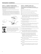
... Step 16. A minimum of appropiate size. • Install the junction box cover. Tighten connections if needed. Verify that is OFF. u Check door alignment with cabinet. u Verify water supply and drain lines are not pinched under the dishwasher, not pinched or in step 1. u Avoid service call that power is not 2-wire with other components. Dishwasher Installation STEP 18 - CONNECT POWER SUPPLY Skip this list after installing your warranty. Check to be sure to...
... Step 16. A minimum of appropiate size. • Install the junction box cover. Tighten connections if needed. Verify that is OFF. u Check door alignment with cabinet. u Verify water supply and drain lines are not pinched under the dishwasher, not pinched or in step 1. u Avoid service call that power is not 2-wire with other components. Dishwasher Installation STEP 18 - CONNECT POWER SUPPLY Skip this list after installing your warranty. Check to be sure to...
Installation Instructions
Page 15
... power supply, then tighten connections. Also check drain line to calibrate your dishwasher for information on the test strip to the section titled "Water Hardness Calibration" in Figure LL using the two screws. The lower set aside in Step 1. • Remove strip from package. • Turn on . Restore power after corrections are turned on the hot water and hold the strip under door panel. Push START/RESET pad one time - u Check for leaks...
... power supply, then tighten connections. Also check drain line to calibrate your dishwasher for information on the test strip to the section titled "Water Hardness Calibration" in Figure LL using the two screws. The lower set aside in Step 1. • Remove strip from package. • Turn on . Restore power after corrections are turned on the hot water and hold the strip under door panel. Push START/RESET pad one time - u Check for leaks...
Installation Instructions
Page 16
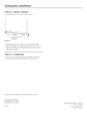
..., Installation Instructions and product samples with the floor to ensure quiet dishwasher operation. Toekick Attachment Screws Figure KK • Replace the toekick and make sure it is against the floor. • Insert and tighten the 2 toekick attachment screws. INSTALL TOEKICK • Locate toekick and screws set aside in contact with the consumer. The toekick should stay in step 5. STEP 24 - Dishwasher Installation STEP...
..., Installation Instructions and product samples with the floor to ensure quiet dishwasher operation. Toekick Attachment Screws Figure KK • Replace the toekick and make sure it is against the floor. • Insert and tighten the 2 toekick attachment screws. INSTALL TOEKICK • Locate toekick and screws set aside in contact with the consumer. The toekick should stay in step 5. STEP 24 - Dishwasher Installation STEP...


