User Manual
Page 1
KTC-510/515/540E B/W and KTC-810C/815C/840CE Color Cameras
KTC-510/515/540E B/W and KTC-810C/815C/840CE Color Cameras
User Manual
Page 5
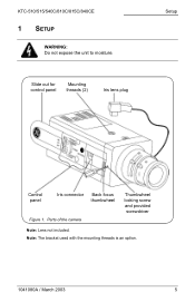
KTC-510/515/540C/810C/815C/840CE 1 SETUP WARNING: Do not expose the unit to moisture. Slide out for control panel Mounting threads (2) Iris lens plug Setup Control panel Iris connector Back focus thumbwheel Figure 1. Note: The bracket used with the mounting threads is an option. 1041080A / March 2003 5 Parts of the camera Thumbwheel locking screw and provided screwdriver Note: Lens not included.
KTC-510/515/540C/810C/815C/840CE 1 SETUP WARNING: Do not expose the unit to moisture. Slide out for control panel Mounting threads (2) Iris lens plug Setup Control panel Iris connector Back focus thumbwheel Figure 1. Note: The bracket used with the mounting threads is an option. 1041080A / March 2003 5 Parts of the camera Thumbwheel locking screw and provided screwdriver Note: Lens not included.

User Manual
Page 6
...Figure 3) to correspond with built-in amplifier (VIDEO type), set up the camera, see Figure 2 and perform the following: Note: For back focus instructions, see section 3, Additional Adjustments. Setup KTC-510/515/540C/810C/815C/840CE To set the lens mode switch to VD. DIP switch Phase ...adjust buttons DD level Lens mode switch Figure 2. Camera controls 1) If you are using an auto iris lens, insert the...
...Figure 3) to correspond with built-in amplifier (VIDEO type), set up the camera, see Figure 2 and perform the following: Note: For back focus instructions, see section 3, Additional Adjustments. Setup KTC-510/515/540C/810C/815C/840CE To set the lens mode switch to VD. DIP switch Phase ...adjust buttons DD level Lens mode switch Figure 2. Camera controls 1) If you are using an auto iris lens, insert the...
User Manual
Page 8
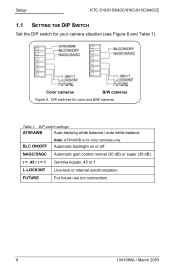
... super (36 dB) r = .45 / r = 1 Gamma equals .45 or 1 L-LOCK/INT Line-lock or internal synchronization FUTURE For future use (no connection) 8 1041080A / March 2003 Setup KTC-510/515/540C/810C/815C/840CE 1.1 SETTING THE DIP SWITCH Set the DIP switch for your camera situation (see Figure 6 and Table 1).
... super (36 dB) r = .45 / r = 1 Gamma equals .45 or 1 L-LOCK/INT Line-lock or internal synchronization FUTURE For future use (no connection) 8 1041080A / March 2003 Setup KTC-510/515/540C/810C/815C/840CE 1.1 SETTING THE DIP SWITCH Set the DIP switch for your camera situation (see Figure 6 and Table 1).
User Manual
Page 9
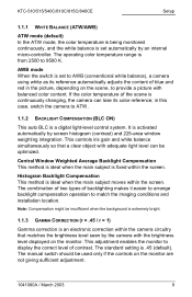
... This adjustment enables the monitor to match the imaging conditions and installation location. Histogram Backlight Compensation This method is continuously changing, the camera can be used only if the controls on the monitor are not giving sufficient adjustment. 1041080A / March 2003 9 The standard setting... white balance simultaneously so that matches the brightness level seen by screen histogram (contrast) and 225-area window weighting integration. KTC-510/515/540C/810C/815C/840CE Setup 1.1.1 WHITE BALANCE (ATW/AWB) ATW mode (default) In the ATW mode, the color temperature is ...
... This adjustment enables the monitor to match the imaging conditions and installation location. Histogram Backlight Compensation This method is continuously changing, the camera can be used only if the controls on the monitor are not giving sufficient adjustment. 1041080A / March 2003 9 The standard setting... white balance simultaneously so that matches the brightness level seen by screen histogram (contrast) and 225-area window weighting integration. KTC-510/515/540C/810C/815C/840CE Setup 1.1.1 WHITE BALANCE (ATW/AWB) ATW mode (default) In the ATW mode, the color temperature is ...

User Manual
Page 10
The phase adjust buttons are used to synchronize cameras even when they are referenced to different phases of the mains supply, which results in rollfree pictures Internal An internal sync generator is used when the camera is being powered off of 12 VDC. 10 1041080A / March 2003 Setup KTC-510/515/540C/810C/815C/840CE 1.1.4 SYNCHRONIZATION (L-LOCK/INT) Line-Lock (external) (default) The sync pulses are connected to the supply frequency.
The phase adjust buttons are used to synchronize cameras even when they are referenced to different phases of the mains supply, which results in rollfree pictures Internal An internal sync generator is used when the camera is being powered off of 12 VDC. 10 1041080A / March 2003 Setup KTC-510/515/540C/810C/815C/840CE 1.1.4 SYNCHRONIZATION (L-LOCK/INT) Line-Lock (external) (default) The sync pulses are connected to the supply frequency.
User Manual
Page 11
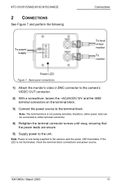
... either power lead can be connected to either terminal connector. 4) Retighten the terminal connector screws until snug, ensuring that the power leads are secure. 5) Supply power to the terminal block. Note: Power is not illuminated, check the terminal block connections and power source. 1041080A / March... 2003 11 If the LED is now being supplied to the camera, and the power LED illuminates. KTC-510/515/540C/810C/815C/840CE 2 CONNECTIONS See Figure 7 and perform the following: Connections To power supply To local or test ...
... either power lead can be connected to either terminal connector. 4) Retighten the terminal connector screws until snug, ensuring that the power leads are secure. 5) Supply power to the terminal block. Note: Power is not illuminated, check the terminal block connections and power source. 1041080A / March... 2003 11 If the LED is now being supplied to the camera, and the power LED illuminates. KTC-510/515/540C/810C/815C/840CE 2 CONNECTIONS See Figure 7 and perform the following: Connections To power supply To local or test ...
User Manual
Page 12
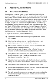
... Adjustments KTC-510/515/540C/810C/815C/840CE 3 ADDITIONAL ADJUSTMENTS 3.1 BACK FOCUS THUMBWHEEL Back focusing is used to match the lens' back focal length with the filter in place, if used) by turning it fully clockwise as viewed from the front of field. It enables the camera to be..., place a filter in front of view that the back focus thumbwheel turns. (See Figure 1.) 5) Adjust the lens' focal position (with the camera's imaging device. To achieve correct back focus, adjustments should always be made in simulated low-light conditions. The lens' depth of field will decrease ...
... Adjustments KTC-510/515/540C/810C/815C/840CE 3 ADDITIONAL ADJUSTMENTS 3.1 BACK FOCUS THUMBWHEEL Back focusing is used to match the lens' back focal length with the filter in place, if used) by turning it fully clockwise as viewed from the front of field. It enables the camera to be..., place a filter in front of view that the back focus thumbwheel turns. (See Figure 1.) 5) Adjust the lens' focal position (with the camera's imaging device. To achieve correct back focus, adjustments should always be made in simulated low-light conditions. The lens' depth of field will decrease ...
User Manual
Page 13
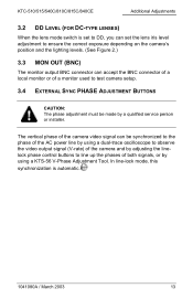
... line-lock mode, this synchronization is set to DD, you can set the lens iris level adjustment to ensure the correct exposure depending on the camera's position and the lighting levels. (See Figure 2.) 3.3 MON OUT (BNC) The monitor output BNC connector can be made by using a dual-...trace oscilloscope to observe the video output signal (V-rate) of the camera and by adjusting the linelock phase control buttons to the phase of both signals, or by a qualified service person or installer. KTC-510/515/540C/810C/815C/840CE Additional Adjustments 3.2 DD LEVEL (FOR DC-TYPE LENSES) When ...
... line-lock mode, this synchronization is set to DD, you can set the lens iris level adjustment to ensure the correct exposure depending on the camera's position and the lighting levels. (See Figure 2.) 3.3 MON OUT (BNC) The monitor output BNC connector can be made by using a dual-...trace oscilloscope to observe the video output signal (V-rate) of the camera and by adjusting the linelock phase control buttons to the phase of both signals, or by a qualified service person or installer. KTC-510/515/540C/810C/815C/840CE Additional Adjustments 3.2 DD LEVEL (FOR DC-TYPE LENSES) When ...
User Manual
Page 14
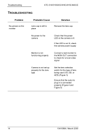
Troubleshooting KTC-510/515/540C/810C/815C/840CE TROUBLESHOOTING Problem No picture on the monitor Probable Cause Solution Lens cap is still in place Remove the lens cap No power to the camera Check that the power LED at the camera is lit If the LED is not lit, check the camera power supply Monitor is... not functioning properly Connect a test monitor to the MON OUT connection to check for a local video signal Camera is not set up properly for the lens type Set the lens selection switch for the type of lens being used (VD, DD, or AES) (...
Troubleshooting KTC-510/515/540C/810C/815C/840CE TROUBLESHOOTING Problem No picture on the monitor Probable Cause Solution Lens cap is still in place Remove the lens cap No power to the camera Check that the power LED at the camera is lit If the LED is not lit, check the camera power supply Monitor is... not functioning properly Connect a test monitor to the MON OUT connection to check for a local video signal Camera is not set up properly for the lens type Set the lens selection switch for the type of lens being used (VD, DD, or AES) (...
User Manual
Page 15
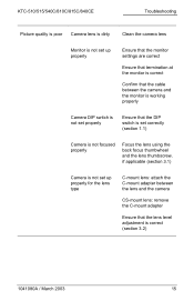
KTC-510/515/540C/810C/815C/840CE Troubleshooting Picture quality is poor Camera lens is dirty Clean the camera lens Monitor is not set up properly Ensure that the monitor settings are correct Ensure that termination at the monitor is correct Confirm that the cable between the camera and the monitor is working properly Camera... DIP switch is not set properly Ensure that the DIP switch is set correctly (section 1.1) Camera is not focused properly Focus the lens using the back ...
KTC-510/515/540C/810C/815C/840CE Troubleshooting Picture quality is poor Camera lens is dirty Clean the camera lens Monitor is not set up properly Ensure that the monitor settings are correct Ensure that termination at the monitor is correct Confirm that the cable between the camera and the monitor is working properly Camera... DIP switch is not set properly Ensure that the DIP switch is set correctly (section 1.1) Camera is not focused properly Focus the lens using the back ...


