User Manual
Page 1
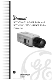
KTC-510/515/540E B/W and KTC-810C/815C/840CE Color Cameras
KTC-510/515/540E B/W and KTC-810C/815C/840CE Color Cameras
User Manual
Page 2
..., if not installed and used or copied only in accordance with the limits for compliance could void the user's authority to change without the prior written permission of this document may cause harmful interference to provide reasonable protection against harmful interference when the equipment is operated in this document. For the latest product specifications, visit GE Interlogix...
..., if not installed and used or copied only in accordance with the limits for compliance could void the user's authority to change without the prior written permission of this document may cause harmful interference to provide reasonable protection against harmful interference when the equipment is operated in this document. For the latest product specifications, visit GE Interlogix...
User Manual
Page 3
KTC-510/515/540C/810C/815C/840CE Table of Contents TABLE OF CONTENTS BEFORE YOU BEGIN 4 1 SETUP 5 1.1 SETTING THE DIP SWITCH 8 1.1.1 White Balance (ATW/AWB 9 1.1.2 Backlight Compensation (BLC ON 9 1.1.3 Gamma Correction (r = .45 / r = 1 9 1.1.4 Synchronization (L-LOCK/INT 10 2 CONNECTIONS 11 3 ADDITIONAL ADJUSTMENTS 12 3.1 BACK FOCUS THUMBWHEEL 12 3.2 DD LEVEL (FOR DC-TYPE LENSES 13 3.3 MON OUT (BNC 13 3.4 EXTERNAL SYNC PHASE ADJUSTMENT BUTTONS .....13 TROUBLESHOOTING 14 1041080A / March 2003 3
KTC-510/515/540C/810C/815C/840CE Table of Contents TABLE OF CONTENTS BEFORE YOU BEGIN 4 1 SETUP 5 1.1 SETTING THE DIP SWITCH 8 1.1.1 White Balance (ATW/AWB 9 1.1.2 Backlight Compensation (BLC ON 9 1.1.3 Gamma Correction (r = .45 / r = 1 9 1.1.4 Synchronization (L-LOCK/INT 10 2 CONNECTIONS 11 3 ADDITIONAL ADJUSTMENTS 12 3.1 BACK FOCUS THUMBWHEEL 12 3.2 DD LEVEL (FOR DC-TYPE LENSES 13 3.3 MON OUT (BNC 13 3.4 EXTERNAL SYNC PHASE ADJUSTMENT BUTTONS .....13 TROUBLESHOOTING 14 1041080A / March 2003 3
User Manual
Page 4
... a qualified service person and should be at the equipment, ready with details before installing or operating this equipment can cause severe bodily injury or equipment damage. ** CAUTION: Improper use of electrical wiring and low-voltage electrical hookups Use this Manual Boldface or button icons highlight command entries. Conventions Used in installing, operating, maintaining, and troubleshooting this product, refer to local codes. To use of...
... a qualified service person and should be at the equipment, ready with details before installing or operating this equipment can cause severe bodily injury or equipment damage. ** CAUTION: Improper use of electrical wiring and low-voltage electrical hookups Use this Manual Boldface or button icons highlight command entries. Conventions Used in installing, operating, maintaining, and troubleshooting this product, refer to local codes. To use of...
User Manual
Page 5
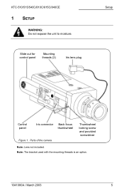
KTC-510/515/540C/810C/815C/840CE 1 SETUP WARNING: Do not expose the unit to moisture. Parts of the camera Thumbwheel locking screw and provided screwdriver Note: Lens not included. Slide out for control panel Mounting threads (2) Iris lens plug Setup Control panel Iris connector Back focus thumbwheel Figure 1. Note: The bracket used with the mounting threads is an option. 1041080A / March 2003 5
KTC-510/515/540C/810C/815C/840CE 1 SETUP WARNING: Do not expose the unit to moisture. Parts of the camera Thumbwheel locking screw and provided screwdriver Note: Lens not included. Slide out for control panel Mounting threads (2) Iris lens plug Setup Control panel Iris connector Back focus thumbwheel Figure 1. Note: The bracket used with the mounting threads is an option. 1041080A / March 2003 5

User Manual
Page 6
Camera controls 1) If you are using an auto iris lens, insert the iris lens plug into the auto iris lens connector. (See Figure 1.) 6 1041080A / March 2003 DIP switch Phase adjust buttons DD level Lens mode switch Figure 2. Figure 3. Lens mode switch settings • For a manual iris lens, set the lens mode switch to AES. 4) If you are using a C-mount lens, screw on the C-mount adapter. 2) Screw the appropriate lens to the camera. 3) Set the lens mode switch (Figure 3) to correspond with built-in amplifier (VIDEO type), set up the camera, see...
Camera controls 1) If you are using an auto iris lens, insert the iris lens plug into the auto iris lens connector. (See Figure 1.) 6 1041080A / March 2003 DIP switch Phase adjust buttons DD level Lens mode switch Figure 2. Figure 3. Lens mode switch settings • For a manual iris lens, set the lens mode switch to AES. 4) If you are using a C-mount lens, screw on the C-mount adapter. 2) Screw the appropriate lens to the camera. 3) Set the lens mode switch (Figure 3) to correspond with built-in amplifier (VIDEO type), set up the camera, see...
User Manual
Page 7
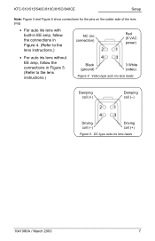
.../810C/815C/840CE Setup Note: Figure 4 and Figure 5 show connections for the pins on the solder side of the lens plug. • For auto iris lens with built-in EE amp, follow the connections in Figure 4. (Refer to the lens instructions.) NC (no connection) Red (9 VAC power) • For auto iris lens without EE amp, follow the connections in Figure 5. (Refer to the lens instructions.) Black (ground) 3 White (video...
.../810C/815C/840CE Setup Note: Figure 4 and Figure 5 show connections for the pins on the solder side of the lens plug. • For auto iris lens with built-in EE amp, follow the connections in Figure 4. (Refer to the lens instructions.) NC (no connection) Red (9 VAC power) • For auto iris lens without EE amp, follow the connections in Figure 5. (Refer to the lens instructions.) Black (ground) 3 White (video...
User Manual
Page 8
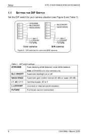
... or 1 L-LOCK/INT Line-lock or internal synchronization FUTURE For future use (no connection) 8 1041080A / March 2003 Color cameras B/W cameras Figure 6. Setup KTC-510/515/540C/810C/815C/840CE 1.1 SETTING THE DIP SWITCH Set the DIP switch for color and B/W cameras Table 1. DIP switches for your camera situation (see Figure 6 and Table 1). DIP switch settings ATW/AWB Auto-tracking white balance / auto white balance BLC ON/OFF Note: ATW/AWB is for...
... or 1 L-LOCK/INT Line-lock or internal synchronization FUTURE For future use (no connection) 8 1041080A / March 2003 Color cameras B/W cameras Figure 6. Setup KTC-510/515/540C/810C/815C/840CE 1.1 SETTING THE DIP SWITCH Set the DIP switch for color and B/W cameras Table 1. DIP switches for your camera situation (see Figure 6 and Table 1). DIP switch settings ATW/AWB Auto-tracking white balance / auto white balance BLC ON/OFF Note: ATW/AWB is for...
User Manual
Page 9
... imaging conditions and installation location. The combination of two types of contrast. The manual switch should be optimized. KTC-510/515/540C/810C/815C/840CE Setup 1.1.1 WHITE BALANCE (ATW/AWB) ATW mode (default) In the ATW mode, the color temperature is being monitored continuously, and the white balance is .45 (default). Histogram Backlight Compensation This method is activated automatically by an internal micro-controller. This adjustment enables the monitor...
... imaging conditions and installation location. The combination of two types of contrast. The manual switch should be optimized. KTC-510/515/540C/810C/815C/840CE Setup 1.1.1 WHITE BALANCE (ATW/AWB) ATW mode (default) In the ATW mode, the color temperature is being monitored continuously, and the white balance is .45 (default). Histogram Backlight Compensation This method is activated automatically by an internal micro-controller. This adjustment enables the monitor...

User Manual
Page 10
Setup KTC-510/515/540C/810C/815C/840CE 1.1.4 SYNCHRONIZATION (L-LOCK/INT) Line-Lock (external) (default) The sync pulses are connected to the supply frequency. The phase adjust buttons are used to synchronize cameras even when they are referenced to different phases of the mains supply, which results in rollfree pictures Internal An internal sync generator is used when the camera is being powered off of 12 VDC. 10 1041080A / March 2003
Setup KTC-510/515/540C/810C/815C/840CE 1.1.4 SYNCHRONIZATION (L-LOCK/INT) Line-Lock (external) (default) The sync pulses are connected to the supply frequency. The phase adjust buttons are used to synchronize cameras even when they are referenced to different phases of the mains supply, which results in rollfree pictures Internal An internal sync generator is used when the camera is being powered off of 12 VDC. 10 1041080A / March 2003
User Manual
Page 11
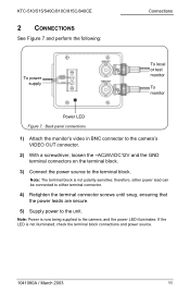
... LED is not polarity sensitive; Back panel connections 1) Attach the monitor's video in BNC connector to the camera's VIDEO OUT connector. 2) With a screwdriver, loosen the ~AC24V/DC12V and the GND terminal connectors on the terminal block. 3) Connect the power source to the terminal block. KTC-510/515/540C/810C/815C/840CE 2 CONNECTIONS See Figure 7 and perform the following: Connections To power supply To local or test monitor To monitor Power LED...
... LED is not polarity sensitive; Back panel connections 1) Attach the monitor's video in BNC connector to the camera's VIDEO OUT connector. 2) With a screwdriver, loosen the ~AC24V/DC12V and the GND terminal connectors on the terminal block. 3) Connect the power source to the terminal block. KTC-510/515/540C/810C/815C/840CE 2 CONNECTIONS See Figure 7 and perform the following: Connections To power supply To local or test monitor To monitor Power LED...
User Manual
Page 12
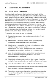
... viewed from the front of the camera. 3) If the lens has a manual iris, set it to infinity by turning the back focus thumbwheel to achieve the sharpest image. 6) Using the included screwdriver, lock the thumbwheel screw. 7) Position the camera for the required view and, if needed, adjust the focus using only the focus ring on the lens. 8) For optimum performance when using an auto iris lens, adjust the lens level according to the camera's position...
... viewed from the front of the camera. 3) If the lens has a manual iris, set it to infinity by turning the back focus thumbwheel to achieve the sharpest image. 6) Using the included screwdriver, lock the thumbwheel screw. 7) Position the camera for the required view and, if needed, adjust the focus using only the focus ring on the lens. 8) For optimum performance when using an auto iris lens, adjust the lens level according to the camera's position...
User Manual
Page 13
... can set the lens iris level adjustment to ensure the correct exposure depending on the camera's position and the lighting levels. (See Figure 2.) 3.3 MON OUT (BNC) The monitor output BNC connector can be synchronized to the phase of the AC power line by using a dual-trace oscilloscope to observe the video output signal (V-rate) of the camera and by adjusting the linelock phase control buttons to line...
... can set the lens iris level adjustment to ensure the correct exposure depending on the camera's position and the lighting levels. (See Figure 2.) 3.3 MON OUT (BNC) The monitor output BNC connector can be synchronized to the phase of the AC power line by using a dual-trace oscilloscope to observe the video output signal (V-rate) of the camera and by adjusting the linelock phase control buttons to line...
User Manual
Page 14
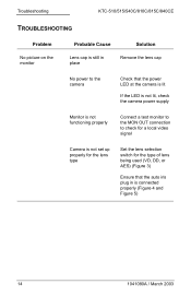
... power LED at the camera is lit If the LED is not lit, check the camera power supply Monitor is not functioning properly Connect a test monitor to the MON OUT connection to check for a local video signal Camera is not set up properly for the lens type Set the lens selection switch for the type of lens being used (VD, DD, or AES) (Figure 3) Ensure that the auto iris plug in is connected...
... power LED at the camera is lit If the LED is not lit, check the camera power supply Monitor is not functioning properly Connect a test monitor to the MON OUT connection to check for a local video signal Camera is not set up properly for the lens type Set the lens selection switch for the type of lens being used (VD, DD, or AES) (Figure 3) Ensure that the auto iris plug in is connected...
User Manual
Page 15
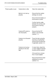
... cable between the camera and the monitor is working properly Camera DIP switch is not set properly Ensure that the DIP switch is set correctly (section 1.1) Camera is not focused properly Focus the lens using the back focus thumbwheel and the lens thumbscrew, if applicable (section 3.1) Camera is not set up properly for the lens type C-mount lens: attach the C-mount adapter between the lens and the camera CS-mount lens: remove the C-mount adapter Ensure that the lens level adjustment...
... cable between the camera and the monitor is working properly Camera DIP switch is not set properly Ensure that the DIP switch is set correctly (section 1.1) Camera is not focused properly Focus the lens using the back focus thumbwheel and the lens thumbscrew, if applicable (section 3.1) Camera is not set up properly for the lens type C-mount lens: attach the C-mount adapter between the lens and the camera CS-mount lens: remove the C-mount adapter Ensure that the lens level adjustment...


