Installation Instructions
Page 3
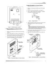
... 6 7 8 9 10 11 12 13 14 15 16 MAGNET CLIP REED SWITCH HOLDER 9712G02A.DSF Figure 3. Remove the module cover and set it aside (Figure 2). 3. PANEL END MODULE END 8573g64A.DSF Figure 5. ...designated for a receiver module, but if a receiver module is not being used, the mounting clips may be used for the 8 Zone Input Module. 5. Gently press the module up the holes on ...module cover (Figure 2). 3. Support Standoff 4. Secure the back-plate to the cabinet using three 1/4 inch #6-32 self-tapping screws (not included). Mounting the Module in an Advent Cabinet 1. Turn the module...
... 6 7 8 9 10 11 12 13 14 15 16 MAGNET CLIP REED SWITCH HOLDER 9712G02A.DSF Figure 3. Remove the module cover and set it aside (Figure 2). 3. PANEL END MODULE END 8573g64A.DSF Figure 5. ...designated for a receiver module, but if a receiver module is not being used, the mounting clips may be used for the 8 Zone Input Module. 5. Gently press the module up the holes on ...module cover (Figure 2). 3. Support Standoff 4. Secure the back-plate to the cabinet using three 1/4 inch #6-32 self-tapping screws (not included). Mounting the Module in an Advent Cabinet 1. Turn the module...
Installation Instructions
Page 4
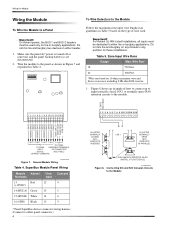
... ZONE 7 ZONE 6 ZONE COMMON ZONE 5 ZONE 4 ZONE COMMON ZONE 3 ZONE 2 ZONE COMMON ZONE 1 1 2 3 4 5 6 7 8 9 10 11 12 13 14 15 16 TO PANEL TO ZONE SUPERBUS TERMINALS INPUT OR CONNECTOR DEVICE (SEE TABLE) (SHARED COMMONS) 9712G03A.DSF Figure 7. Do not mix fire and burglary bus devices on 10 ohms maximum wire and device resistance including 2.0K ohm EOL resistor. 1. Zone Input Wire Runs Gauge Max. Table 5. General Module...
... ZONE 7 ZONE 6 ZONE COMMON ZONE 5 ZONE 4 ZONE COMMON ZONE 3 ZONE 2 ZONE COMMON ZONE 1 1 2 3 4 5 6 7 8 9 10 11 12 13 14 15 16 TO PANEL TO ZONE SUPERBUS TERMINALS INPUT OR CONNECTOR DEVICE (SEE TABLE) (SHARED COMMONS) 9712G03A.DSF Figure 7. Do not mix fire and burglary bus devices on 10 ohms maximum wire and device resistance including 2.0K ohm EOL resistor. 1. Zone Input Wire Runs Gauge Max. Table 5. General Module...
Installation Instructions
Page 5
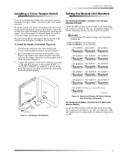
... 1 234567 8 1 234567 8 UNIT NUMBER 6 UNIT NUMBER 7 UNIT NUMBER 8 M ON M ON M ON A A A 1 234567 8 1 234567 8 1 234567 8 UNIT NUMBER 9 UNIT NUMBER 10 UNIT NUMBER 11 M ON M ON M ON A A A 1 234567 8 1 234567 8 1 234567 8 UNIT NUMBER 12 UNIT NUMBER 13 UNIT NUMBER 14 M ON M ON M ON A A A 1 234567 8 1 234567 ... set when powering up . - MODULE BACK-PLATE MODULE COVER MAGNET TO ANY ZONE INPUT MAGNET CLIP REED SWITCH 2.0K OHM EOL RESISTOR (49-467) 9712G12A.DSF Figure 9. Module Unit Number DIP Switch Settings (Non-SuperBus 2000 panels) On Concord (software versions...
... 1 234567 8 1 234567 8 UNIT NUMBER 6 UNIT NUMBER 7 UNIT NUMBER 8 M ON M ON M ON A A A 1 234567 8 1 234567 8 1 234567 8 UNIT NUMBER 9 UNIT NUMBER 10 UNIT NUMBER 11 M ON M ON M ON A A A 1 234567 8 1 234567 8 1 234567 8 UNIT NUMBER 12 UNIT NUMBER 13 UNIT NUMBER 14 M ON M ON M ON A A A 1 234567 8 1 234567 ... set when powering up . - MODULE BACK-PLATE MODULE COVER MAGNET TO ANY ZONE INPUT MAGNET CLIP REED SWITCH 2.0K OHM EOL RESISTOR (49-467) 9712G12A.DSF Figure 9. Module Unit Number DIP Switch Settings (Non-SuperBus 2000 panels) On Concord (software versions...
