Installation Instructions
Page 1
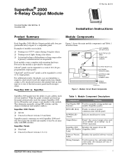
... the installed software version. Examples of 124 (24 preprogrammed) output points. Each module comes complete with mounting hardware. SuperBus® 2000 4-Relay Output Module ITI Part No. 60-770 Document Number: 466-1608 Rev. B November 2000 8557109A.DS4 Installation Instructions Product Summary Module Components Each SuperBus 2000 4-Relay Output module adds four programmable relay outputs to the module. u Activating backup cellular phones or long-range radios...
... the installed software version. Examples of 124 (24 preprogrammed) output points. Each module comes complete with mounting hardware. SuperBus® 2000 4-Relay Output Module ITI Part No. 60-770 Document Number: 466-1608 Rev. B November 2000 8557109A.DS4 Installation Instructions Product Summary Module Components Each SuperBus 2000 4-Relay Output module adds four programmable relay outputs to the module. u Activating backup cellular phones or long-range radios...

Installation Instructions
Page 2
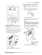
...module draws 12 mA typical when outputs are not energized (idle). u Do not exceed the module output relay contact ratings (4A @ 24VDC, 4A @ 24VAC, 1A @ 70VAC maximum). u Inside a SuperBus Module cabinet (60...500 ft. Removing the Cover 2. Place the back-plate on a Wall 1. Secure the back-plate to the cabinet Installation Instructions for bus devices and hardwired detectors...4000 feet using self or remotely powered devices with included screws. 2 SuperBus® 2000 4-Relay Output Module Installation Guidelines Installation Guidelines Installation u For the maximum number of bus ...
...module draws 12 mA typical when outputs are not energized (idle). u Do not exceed the module output relay contact ratings (4A @ 24VDC, 4A @ 24VAC, 1A @ 70VAC maximum). u Inside a SuperBus Module cabinet (60...500 ft. Removing the Cover 2. Place the back-plate on a Wall 1. Secure the back-plate to the cabinet Installation Instructions for bus devices and hardwired detectors...4000 feet using self or remotely powered devices with included screws. 2 SuperBus® 2000 4-Relay Output Module Installation Guidelines Installation Guidelines Installation u For the maximum number of bus ...
Installation Instructions
Page 3
... SIDE TAB PANEL CABINET (COVER NOT SHOWN) MOUNT WITH SELF TAPPING SCREWS MOUNTED MODULE ROOM FOR 3RD 9712G11A.DSF MODULE Figure 4. Remove the module cover and set it aside (Figure 2). 3. Note The two mounting clips in Concord Cabinet SuperBus® 2000 4-Relay Output Module 3 Secure the back-plate to the cabinet using three ¼-inch #6-32 self-tapping...
... SIDE TAB PANEL CABINET (COVER NOT SHOWN) MOUNT WITH SELF TAPPING SCREWS MOUNTED MODULE ROOM FOR 3RD 9712G11A.DSF MODULE Figure 4. Remove the module cover and set it aside (Figure 2). 3. Note The two mounting clips in Concord Cabinet SuperBus® 2000 4-Relay Output Module 3 Secure the back-plate to the cabinet using three ¼-inch #6-32 self-tapping...


