
Gateway Quick Start Guide for Windows 7
Page 22
... be illegal. 22 - Turning On/Off a WiFi Network Connection Most computers feature a 'WiFi' button that turns the network connection on or off all devices before boarding an aircraft; Click on or off, or control what is shared over the network with the members of an ad-hoc wireless network. they may...
... be illegal. 22 - Turning On/Off a WiFi Network Connection Most computers feature a 'WiFi' button that turns the network connection on or off all devices before boarding an aircraft; Click on or off, or control what is shared over the network with the members of an ad-hoc wireless network. they may...
Gateway Quick Start Guide for Windows 7
Page 50
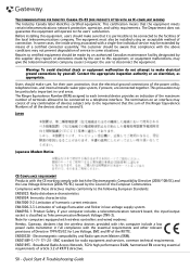
...using an acceptable method of the local telecommunications company. Note for computers equipped with wireless controllers and wired modems: Hereby, Gateway, declares that the wireless devices provided with a single-line individual service may not prevent degradation of all the devices does ...precaution may consist of any combination of devices subject only to disconnect the equipment. If your computer includes a telecommunication network board, the input/output socket is permissible to be particularly important in some cases, the inside wiring associated with this equipment, ...
...using an acceptable method of the local telecommunications company. Note for computers equipped with wireless controllers and wired modems: Hereby, Gateway, declares that the wireless devices provided with a single-line individual service may not prevent degradation of all the devices does ...precaution may consist of any combination of devices subject only to disconnect the equipment. If your computer includes a telecommunication network board, the input/output socket is permissible to be particularly important in some cases, the inside wiring associated with this equipment, ...
Service Guide
Page 7
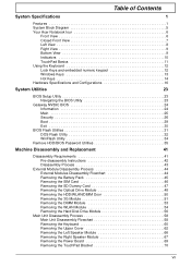
... keypad 12 Windows Keys 13 Hot Keys 14 Hardware Specifications and Configurations 16 System Utilities 23 BIOS Setup Utility 23 Navigating the BIOS Utility 23 Gateway NV59C BIOS 24 Information 24 Main 25 Security 26 Boot 29 Exit 30 BIOS Flash Utilities 31 DOS Flash Utility 32 WinFlash Utility 34 Remove... 58 Removing the Keyboard 60 Removing the Upper Cover 62 Removing the Left Speaker Module 66 Removing the Right Speaker Module 67 Removing the Power Board 69 Removing the TouchPad Bracket 70 VII
... keypad 12 Windows Keys 13 Hot Keys 14 Hardware Specifications and Configurations 16 System Utilities 23 BIOS Setup Utility 23 Navigating the BIOS Utility 23 Gateway NV59C BIOS 24 Information 24 Main 25 Security 26 Boot 29 Exit 30 BIOS Flash Utilities 31 DOS Flash Utility 32 WinFlash Utility 34 Remove... 58 Removing the Keyboard 60 Removing the Upper Cover 62 Removing the Left Speaker Module 66 Removing the Right Speaker Module 67 Removing the Power Board 69 Removing the TouchPad Bracket 70 VII

Service Guide
Page 8
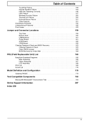
...84 LCD Module Disassembly Flowchart 84 Removing the LCD Assembly 85 Removing the LCD Bezel 88 Removing the Camera Module 89 Removing the Inverter Board 90 Removing the LCD Panel 92 Removing the LCD Brackets and FPC Cable 94 Removing the Microphone Cable 96 Removing the Antennas 98 ...the Antennas 100 Replacing the Microphone Cable 102 Replacing the LCD Brackets and FPC Cable 103 Replacing the LCD Panel 105 Replacing the Inverter Board 106 Replacing the Camera Module 107 Replacing the LCD Bezel 108 Replacing the LCD Assembly 109 Main Module Reassembly Procedure 112 Replacing the ...
...84 LCD Module Disassembly Flowchart 84 Removing the LCD Assembly 85 Removing the LCD Bezel 88 Removing the Camera Module 89 Removing the Inverter Board 90 Removing the LCD Panel 92 Removing the LCD Brackets and FPC Cable 94 Removing the Microphone Cable 96 Removing the Antennas 98 ...the Antennas 100 Replacing the Microphone Cable 102 Replacing the LCD Brackets and FPC Cable 103 Replacing the LCD Panel 105 Replacing the Inverter Board 106 Replacing the Camera Module 107 Replacing the LCD Bezel 108 Replacing the LCD Assembly 109 Main Module Reassembly Procedure 112 Replacing the ...
Service Guide
Page 9
...Problems 152 Undetermined Problems 152 Post Codes 153 Jumper and Connector Locations 159 Top View 159 Bottom View 160 USB/B Board 161 Power Board 161 3G/B Board 162 CR/B Board 162 Clearing Password Check and BIOS Recovery 163 Clearing Password Check 163 Clear CMOS Jumper 163 BIOS Recovery by Crisis... Main Assembly 166 Upper Assembly 167 LCD Assembly 168 FRU List 169 Screw List 176 Model Definition and Configuration 178 Gateway NV59C 179 Test Compatible Components 193 Microsoft® Windows® 7 Environment Test 194 Online Support Information 207 Index 209 IX
...Problems 152 Undetermined Problems 152 Post Codes 153 Jumper and Connector Locations 159 Top View 159 Bottom View 160 USB/B Board 161 Power Board 161 3G/B Board 162 CR/B Board 162 Clearing Password Check and BIOS Recovery 163 Clearing Password Check 163 Clear CMOS Jumper 163 BIOS Recovery by Crisis... Main Assembly 166 Upper Assembly 167 LCD Assembly 168 FRU List 169 Screw List 176 Model Definition and Configuration 178 Gateway NV59C 179 Test Compatible Components 193 Microsoft® Windows® 7 Environment Test 194 Online Support Information 207 Index 209 IX
Service Guide
Page 54
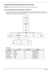
.... External Modules Disassembly Flowchart The flowchart below gives you a graphic representation of the external module disassembly sequence and instructs you must first remove the switch board. For example, if you want to remove the keyboard, you on the components that need to be removed during servicing.
.... External Modules Disassembly Flowchart The flowchart below gives you a graphic representation of the external module disassembly sequence and instructs you must first remove the switch board. For example, if you want to remove the keyboard, you on the components that need to be removed during servicing.
Service Guide
Page 64
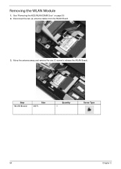
Move the antenna away and remove the one (1) screw to release the WLAN Board. Step WLAN Module Size M2*3 Quantity 1 Screw Type 54 Chapter 3 Removing the WLAN Module 1. See "Removing the HDD/WLAN/DIMM Door" on page 50. 2. Disconnect the two (2) antenna cables from the WLAN Board. 3.
Move the antenna away and remove the one (1) screw to release the WLAN Board. Step WLAN Module Size M2*3 Quantity 1 Screw Type 54 Chapter 3 Removing the WLAN Module 1. See "Removing the HDD/WLAN/DIMM Door" on page 50. 2. Disconnect the two (2) antenna cables from the WLAN Board. 3.
Service Guide
Page 65
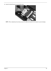
Detach the WLAN Board from the WLAN socket. Chapter 3 55 NOTE: When reattaching the antennas, ensure the cables are tucked into the chassis to prevent damage. 4.
Detach the WLAN Board from the WLAN socket. Chapter 3 55 NOTE: When reattaching the antennas, ensure the cables are tucked into the chassis to prevent damage. 4.

Service Guide
Page 68
... before proceeding Remove Keyboard Remove Upper Cover Upper Cover Lower Cover Remove Power Board Remove Left Speaker Module Remove Right Speaker Module Remove USB Board Remove TouchPad Bracket Remove USB Board Remove Card Reader Board Remove Mainboard Remove Thermal Module Remove CPU Remove Bluetooth Board Screw List Step Lower Cover Lower Cover Upper Cover Power...
... before proceeding Remove Keyboard Remove Upper Cover Upper Cover Lower Cover Remove Power Board Remove Left Speaker Module Remove Right Speaker Module Remove USB Board Remove TouchPad Bracket Remove USB Board Remove Card Reader Board Remove Mainboard Remove Thermal Module Remove CPU Remove Bluetooth Board Screw List Step Lower Cover Lower Cover Upper Cover Power...
Service Guide
Page 79
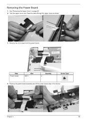
Pass the cable through the upper cover as shown. 3. Remove two (2) screws from the power board. Chapter 3 69 Step Power board Size M2*3 Quantity 2 Screw Type 4. Remove the power board assembly and lift the power board clear of the device. Removing the Power Board 1. See "Removing the Upper Cover" on page 62. 2. Turn the upper cover over.
Pass the cable through the upper cover as shown. 3. Remove two (2) screws from the power board. Chapter 3 69 Step Power board Size M2*3 Quantity 2 Screw Type 4. Remove the power board assembly and lift the power board clear of the device. Removing the Power Board 1. See "Removing the Upper Cover" on page 62. 2. Turn the upper cover over.
Service Guide
Page 80
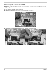
See "Removing the Upper Cover" on page 62. 2. Lift the FFC to detach the adhesive securing the cable to the Upper Cover. 3. To replace the TouchPad Board, replace the entire Upper Cover. 1. Release the FFC locking latch and disconnect the TouchPad FFC from the cover. 70 Chapter 3 Removing the TouchPad Bracket IMPORTANT: The TouchPad Board cannot be removed individually.
See "Removing the Upper Cover" on page 62. 2. Lift the FFC to detach the adhesive securing the cable to the Upper Cover. 3. To replace the TouchPad Board, replace the entire Upper Cover. 1. Release the FFC locking latch and disconnect the TouchPad FFC from the cover. 70 Chapter 3 Removing the TouchPad Bracket IMPORTANT: The TouchPad Board cannot be removed individually.
Service Guide
Page 82
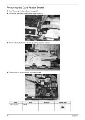
Removing the Card Reader Board 1. Remove one (1) screw from the chassis by pulling up on page 62. 2. Remove the cable from the card reader board. Step Card Reader Size M2*3 Quantity 1 Screw Type 72 Chapter 3 See "Removing the Upper Cover" on the adhesive. 4. Unlock the mainboard to card reader cable connector. 3.
Removing the Card Reader Board 1. Remove one (1) screw from the chassis by pulling up on page 62. 2. Remove the cable from the card reader board. Step Card Reader Size M2*3 Quantity 1 Screw Type 72 Chapter 3 See "Removing the Upper Cover" on the adhesive. 4. Unlock the mainboard to card reader cable connector. 3.
Service Guide
Page 83
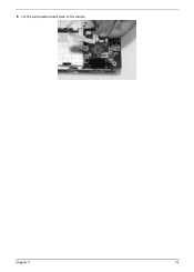
5. Chapter 3 73 Lift the card reader board clear of the device.
5. Chapter 3 73 Lift the card reader board clear of the device.
Service Guide
Page 84
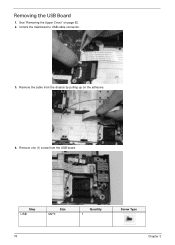
Unlock the mainboard to USB cable connector. 3. Remove the cable from the USB board. Step USB Size M2*3 Quantity 1 Screw Type 74 Chapter 3 See "Removing the Upper Cover" on the adhesive. 4. Remove one (1) screw from the chassis by pulling up on page 62. 2. Removing the USB Board 1.
Unlock the mainboard to USB cable connector. 3. Remove the cable from the USB board. Step USB Size M2*3 Quantity 1 Screw Type 74 Chapter 3 See "Removing the Upper Cover" on the adhesive. 4. Remove one (1) screw from the chassis by pulling up on page 62. 2. Removing the USB Board 1.

Service Guide
Page 85
Lift the USB board clear of the device. Chapter 3 75 5.
Lift the USB board clear of the device. Chapter 3 75 5.
Service Guide
Page 86
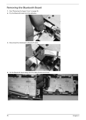
See "Removing the Upper Cover" on page 62. 2. Disconnect the mainboard to Bluetooth cable. 4. Pry the Bluetooth board from the cable channel as shown. 76 Chapter 3 Lift the Bluetooth board away from the adhesive. 3. Removing the Bluetooth Board 1.
See "Removing the Upper Cover" on page 62. 2. Disconnect the mainboard to Bluetooth cable. 4. Pry the Bluetooth board from the cable channel as shown. 76 Chapter 3 Lift the Bluetooth board away from the adhesive. 3. Removing the Bluetooth Board 1.
Service Guide
Page 89
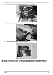
Remove the mainboard from the chassis and turn the mainboard over . Chapter 3 79 NOTE: Circuit boards >10 cm² have been highlighted with a yellow rectangle as shown in the previous image. 6. Please detach the Circuit board and follow local regulations for disposal. Carefully turn it over and place it on a clean, dust-free surface. 7. Disconnect the power cable. 8.
Remove the mainboard from the chassis and turn the mainboard over . Chapter 3 79 NOTE: Circuit boards >10 cm² have been highlighted with a yellow rectangle as shown in the previous image. 6. Please detach the Circuit board and follow local regulations for disposal. Carefully turn it over and place it on a clean, dust-free surface. 7. Disconnect the power cable. 8.
Service Guide
Page 94
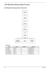
LCD Module Disassembly Process LCD Module Disassembly Flowchart Remove LCD Assembly Remove LCD Bezel Remove Camera Module Remove Inverter Board Remove LCD Panel Remove LCD Brackets and FPC Cable Remove Antennas Remove Microphone Cable Screw List Step LCD Bezel LCD Panel LCD Brackets Inverter Board LCD Assembly Screw M2.5*6 M2.5*6 M2*3 M2.5*5 M2.5*8 Quantity 2 2 6 1 4 Part No. 86.WJ802.003 86.WJ802.003 86.WJ802.004 86.WJ802.001 86.WJ802.002 84 Chapter 3
LCD Module Disassembly Process LCD Module Disassembly Flowchart Remove LCD Assembly Remove LCD Bezel Remove Camera Module Remove Inverter Board Remove LCD Panel Remove LCD Brackets and FPC Cable Remove Antennas Remove Microphone Cable Screw List Step LCD Bezel LCD Panel LCD Brackets Inverter Board LCD Assembly Screw M2.5*6 M2.5*6 M2*3 M2.5*5 M2.5*8 Quantity 2 2 6 1 4 Part No. 86.WJ802.003 86.WJ802.003 86.WJ802.004 86.WJ802.001 86.WJ802.002 84 Chapter 3
Service Guide
Page 100
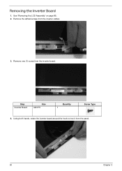
See "Removing the LCD Assembly" on page 85. 2. Step Inverter Board Size M2.5*5 Quantity 1 Screw Type 4. Remove the adhesive tape from the panel. 90 Chapter 3 Using both hands, rotate the inverter board around the hook to free it from the inverter cables. 3. Removing the Inverter Board 1. Remove one (1) screw from the inverter board.
See "Removing the LCD Assembly" on page 85. 2. Step Inverter Board Size M2.5*5 Quantity 1 Screw Type 4. Remove the adhesive tape from the panel. 90 Chapter 3 Using both hands, rotate the inverter board around the hook to free it from the inverter cables. 3. Removing the Inverter Board 1. Remove one (1) screw from the inverter board.

Service Guide
Page 101
Chapter 3 91 Turn the board over and disconnect the cable. 5.
Chapter 3 91 Turn the board over and disconnect the cable. 5.


