8511418 - Component Replacement Manual
Page 1
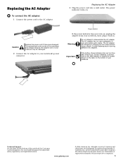
... adapter: 1 Connect the power cord to disassemble the AC adapter. www.gateway.com © 2006 Gateway, Inc. The replacement cord must be damaged. 2 Connect the AC adapter to your notebook. Important If the battery charge indicator does not turn on the bottom of the same type and voltage rating as the original cord or your notebook may be of your notebook's power connector. Technical Support See the label on . The power indicator turns...
... adapter: 1 Connect the power cord to disassemble the AC adapter. www.gateway.com © 2006 Gateway, Inc. The replacement cord must be damaged. 2 Connect the AC adapter to your notebook. Important If the battery charge indicator does not turn on the bottom of the same type and voltage rating as the original cord or your notebook may be of your notebook's power connector. Technical Support See the label on . The power indicator turns...
8511418 - Component Replacement Manual
Page 2
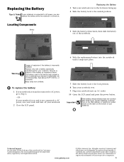
... AC outlet. 10 Open the LCD panel and press the power button. Important If the battery charge indicator does not turn off your notebook is connected to AC power, go to the unlock position. 5 Slide the battery release latch, then slide the battery out of Gateway, Inc. Gateway and eMachines are trademarks or registered trademarks of your notebook is on and is on . Technical Support See the label on...
... AC outlet. 10 Open the LCD panel and press the power button. Important If the battery charge indicator does not turn off your notebook is connected to AC power, go to the unlock position. 5 Slide the battery release latch, then slide the battery out of Gateway, Inc. Gateway and eMachines are trademarks or registered trademarks of your notebook is on and is on . Technical Support See the label on...
8511418 - Component Replacement Manual
Page 3
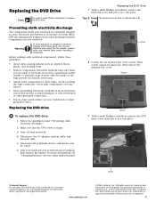
... and moving parts, turn off your notebook. 4 Disconnect the AC adapter, modem cable, and network cable. 5 Disconnect all peripheral devices and remove any surface. • Wear a grounding wrist strap (available at most electronics stores) and attach it to replace the DVD drive. Never slide components over so the bottom is marked with notebook components, follow these screws cannot be removed), then remove the memory bay cover. Do...
... and moving parts, turn off your notebook. 4 Disconnect the AC adapter, modem cable, and network cable. 5 Disconnect all peripheral devices and remove any surface. • Wear a grounding wrist strap (available at most electronics stores) and attach it to replace the DVD drive. Never slide components over so the bottom is marked with notebook components, follow these screws cannot be removed), then remove the memory bay cover. Do...
8511418 - Component Replacement Manual
Page 4
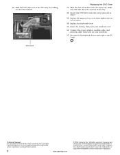
... Replace the memory bay cover, then tighten the six cover screws. 14 Replace the keyboard screw. 15 Insert the battery, then turn your notebook over. 16 Connect the power adapter, modem cable, and network cable, then turn on your hardware guide for Customer Care Information. See your notebook. 17 Reconnect all peripheral devices and replace any PC Cards. 10 Slide the DVD drive out of Gateway, Inc. DVD bracket Replacing the DVD Drive 11 Slide the new DVD drive into the drive bay. Gateway...
... Replace the memory bay cover, then tighten the six cover screws. 14 Replace the keyboard screw. 15 Insert the battery, then turn your notebook over. 16 Connect the power adapter, modem cable, and network cable, then turn on your hardware guide for Customer Care Information. See your notebook. 17 Reconnect all peripheral devices and replace any PC Cards. 10 Slide the DVD drive out of Gateway, Inc. DVD bracket Replacing the DVD Drive 11 Slide the new DVD drive into the drive bay. Gateway...
8511418 - Component Replacement Manual
Page 5
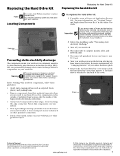
... create a Drivers and Applications Recovery disc, Gateway may send you are ready to use them. Replacing the Hard Drive Kit Replacing the Hard Drive Kit Replacing the hard drive kit Tools You need the operating system disc that came with your online hardware guide. 7 Remove the two hard drive bay cover screws, slide the hard drive bay cover, then remove it to dangerous electrical voltages and moving parts, turn off your notebook. 4 Disconnect the AC adapter, modem cable, and network cable. 5 Disconnect all peripheral devices and remove...
... create a Drivers and Applications Recovery disc, Gateway may send you are ready to use them. Replacing the Hard Drive Kit Replacing the Hard Drive Kit Replacing the hard drive kit Tools You need the operating system disc that came with your online hardware guide. 7 Remove the two hard drive bay cover screws, slide the hard drive bay cover, then remove it to dangerous electrical voltages and moving parts, turn off your notebook. 4 Disconnect the AC adapter, modem cable, and network cable. 5 Disconnect all peripheral devices and remove...
8511418 - Component Replacement Manual
Page 6
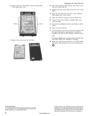
... the Operating System Recovery CD/DVD when prompted, then follow the on-screen instructions. 8 Remove the four screws that secure the cover to the drive. 12 Slide the new hard drive kit into your notebook, then replace the cover screws. 13 Insert the battery and turn your notebook over. 14 Connect the power adapter, modem cable, and network cable. 15 Reconnect all peripheral devices and replace any PC Cards. 16 Turn on your notebook. 17 If the hard drive was...
... the Operating System Recovery CD/DVD when prompted, then follow the on-screen instructions. 8 Remove the four screws that secure the cover to the drive. 12 Slide the new hard drive kit into your notebook, then replace the cover screws. 13 Insert the battery and turn your notebook over. 14 Connect the power adapter, modem cable, and network cable. 15 Reconnect all peripheral devices and replace any PC Cards. 16 Turn on your notebook. 17 If the hard drive was...
8511418 - Component Replacement Manual
Page 7
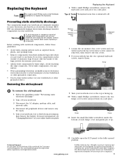
... electrical voltages and moving parts, turn off your notebook. 3 Disconnect the AC adapter, modem cable, and network cable. 4 Disconnect all peripheral devices and remove any surface. • Wear a grounding wrist strap (available at most electronics stores) and attach it to use them. Removing the old keyboard Replacing the Keyboard 6 With a small Phillips screwdriver, remove the keyboard screw and put them in a safe place. Technical Support See the label...
... electrical voltages and moving parts, turn off your notebook. 3 Disconnect the AC adapter, modem cable, and network cable. 4 Disconnect all peripheral devices and remove any surface. • Wear a grounding wrist strap (available at most electronics stores) and attach it to use them. Removing the old keyboard Replacing the Keyboard 6 With a small Phillips screwdriver, remove the keyboard screw and put them in a safe place. Technical Support See the label...
8511418 - Component Replacement Manual
Page 8
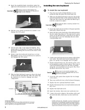
... prevent damage to close the LCD panel. 7 Close the LCD panel, then replace the two hinge cover screws. 8 Turn your notebook over so the bottom is almost face-up . 9 Replace the two optional keyboard screws. 10 Replace the memory bay cover and wireless network bay cover. 11 Replace the keyboard screw. 12 Insert the battery, then turn your notebook over. 13 Connect the power adapter, the modem cable, and the network cable, then turn on the front edge of...
... prevent damage to close the LCD panel. 7 Close the LCD panel, then replace the two hinge cover screws. 8 Turn your notebook over so the bottom is almost face-up . 9 Replace the two optional keyboard screws. 10 Replace the memory bay cover and wireless network bay cover. 11 Replace the keyboard screw. 12 Insert the battery, then turn your notebook over. 13 Connect the power adapter, the modem cable, and the network cable, then turn on the front edge of...
8511418 - Component Replacement Manual
Page 9
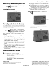
... avoid exposure to replace the memory module. All rights reserved. Locating Components Memory bay Replacing the Memory Module 4 Disconnect all peripheral devices and remove any surface. • Wear a grounding wrist strap (available at most electronics stores) and attach it in a safe place. Replacing the Memory Module Tools You need a small Phillips screwdriver to dangerous electrical voltages and moving parts, turn off your notebook. 3 Disconnect the AC adapter, modem cable, and network cable.
... avoid exposure to replace the memory module. All rights reserved. Locating Components Memory bay Replacing the Memory Module 4 Disconnect all peripheral devices and remove any surface. • Wear a grounding wrist strap (available at most electronics stores) and attach it in a safe place. Replacing the Memory Module Tools You need a small Phillips screwdriver to dangerous electrical voltages and moving parts, turn off your notebook. 3 Disconnect the AC adapter, modem cable, and network cable.
8511418 - Component Replacement Manual
Page 10
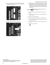
... inserted in place. 12 Replace the memory bay cover, then tighten the six cover screws. 13 Replace the keyboard screw. 14 Insert the battery, then turn your notebook over. 15 Connect the power adapter, the modem cable, and the network cable. 16 Reconnect all peripheral devices and replace any PC Cards. 17 Turn on your hardware guide for Customer Care Information. Replacing the Memory Module 10 Hold the new or replacement module at each end of their...
... inserted in place. 12 Replace the memory bay cover, then tighten the six cover screws. 13 Replace the keyboard screw. 14 Insert the battery, then turn your notebook over. 15 Connect the power adapter, the modem cable, and the network cable. 16 Reconnect all peripheral devices and replace any PC Cards. 17 Turn on your hardware guide for Customer Care Information. Replacing the Memory Module 10 Hold the new or replacement module at each end of their...
8511418 - Component Replacement Manual
Page 11
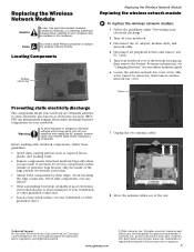
... dangerous electrical voltages and moving parts, turn off your notebook. 3 Disconnect the AC adapter, modem cable, and network cable. 4 Disconnect all peripheral devices and remove any surface. • Wear a grounding wrist strap (available at most electronics stores) and attach it to use them. See your hardware guide for your online hardware guide. 6 Loosen the wireless network bay cover screw (this notebook. Before working with notebook components, follow these guidelines: •...
... dangerous electrical voltages and moving parts, turn off your notebook. 3 Disconnect the AC adapter, modem cable, and network cable. 4 Disconnect all peripheral devices and remove any surface. • Wear a grounding wrist strap (available at most electronics stores) and attach it to use them. See your hardware guide for your online hardware guide. 6 Loosen the wireless network bay cover screw (this notebook. Before working with notebook components, follow these guidelines: •...
8511418 - Component Replacement Manual
Page 12
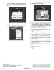
... the light gray antenna cable to the connector labelled AUX or A. 15 Replace the wireless network bay cover, then tighten the cover screw. 16 Insert the battery, then turn your notebook over. 17 Connect the power adapter, the modem cable, and the network cable. 18 Reconnect all peripheral devices and replace any PC Cards. 19 Turn on your card is held by clips, press the module down until the module tilts upward. Technical Support...
... the light gray antenna cable to the connector labelled AUX or A. 15 Replace the wireless network bay cover, then tighten the cover screw. 16 Insert the battery, then turn your notebook over. 17 Connect the power adapter, the modem cable, and the network cable. 18 Reconnect all peripheral devices and replace any PC Cards. 19 Turn on your card is held by clips, press the module down until the module tilts upward. Technical Support...
8511381 - Hardware Reference Guide (Japan)
Page 21
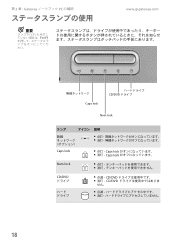
第 2 章 : Gateway PC の確認 www.jp.gateway.com 重要 FN+F1 Caps lock CD/DVD Num lock ランプ Caps lock Caps lock A Caps lock Num lock 1 CD/DVD CD/DVD CD/DVD せん。 18
第 2 章 : Gateway PC の確認 www.jp.gateway.com 重要 FN+F1 Caps lock CD/DVD Num lock ランプ Caps lock Caps lock A Caps lock Num lock 1 CD/DVD CD/DVD CD/DVD せん。 18
8511381 - Hardware Reference Guide (Japan)
Page 37
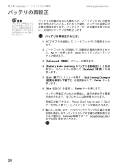
第 2 章 : Gateway PC の確認 www.jp.gateway.com 重要 PC 1 AC PC 2 PC F2 BIOS 3 [Advanced 4 [Battery Auto Learning Enabled 5 [Exit Exit Saving Changes ENTER 6 [Yes ENTER Press[Esc]key to exit([Esc 7 ESC Gateway jp.gateway.com 34
第 2 章 : Gateway PC の確認 www.jp.gateway.com 重要 PC 1 AC PC 2 PC F2 BIOS 3 [Advanced 4 [Battery Auto Learning Enabled 5 [Exit Exit Saving Changes ENTER 6 [Yes ENTER Press[Esc]key to exit([Esc 7 ESC Gateway jp.gateway.com 34
8511381 - Hardware Reference Guide (Japan)
Page 61
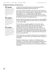
... per FCC Part 15 Low power, Radio transmitter type devices (radio frequency (RF) wireless communication devices), operating in the 2.4 GHz band and/or 5.15 - 5.35 GHz band, may be embedded in your notebook, is well below the RF exposure limits as set a general guideline of 20 cm (8 inches) separation between the device and the body, for service. Contact Gateway for use in the...
... per FCC Part 15 Low power, Radio transmitter type devices (radio frequency (RF) wireless communication devices), operating in the 2.4 GHz band and/or 5.15 - 5.35 GHz band, may be embedded in your notebook, is well below the RF exposure limits as set a general guideline of 20 cm (8 inches) separation between the device and the body, for service. Contact Gateway for use in the...

8511381 - Hardware Reference Guide (Japan)
Page 62
... with FCC rules. This equipment generates, uses, and can be used in a particular installation. Caution Changes or modifications not expressly approved by one or more of the FCC rules. FCC declaration of the used notebook properly according to federal, state and local laws. If this equipment are: shielded video cable when an external monitor is connected. However, there is no guarantee...
... with FCC rules. This equipment generates, uses, and can be used in a particular installation. Caution Changes or modifications not expressly approved by one or more of the FCC rules. FCC declaration of the used notebook properly according to federal, state and local laws. If this equipment are: shielded video cable when an external monitor is connected. However, there is no guarantee...
8511381 - Hardware Reference Guide (Japan)
Page 63
...notify you disconnect the equipment until the problem is designed to be connected to the telephone network or premises wiring using a compatible modular jack which may be connected to the following two conditions: (1) this device may cause undesired operation. Mercury Warning Hg Warning The lamp ..., known to the State of devices that may not cause harmful interference, and (2) this device. Do not put in response to the telephone company. See installation instructions for use with Part 68 of the Code of service may result in the devices not ringing in trash. Excessive ...
...notify you disconnect the equipment until the problem is designed to be connected to the telephone network or premises wiring using a compatible modular jack which may be connected to the following two conditions: (1) this device may cause undesired operation. Mercury Warning Hg Warning The lamp ..., known to the State of devices that may not cause harmful interference, and (2) this device. Do not put in response to the telephone company. See installation instructions for use with Part 68 of the Code of service may result in the devices not ringing in trash. Excessive ...

8511381 - Hardware Reference Guide (Japan)
Page 64
... 1991 makes it is subject to maintain uninterrupted service. Connection to party line service is sent, an identification of the business, other entity, or other individual sending the message, and the telephone number of this happens, the telephone company will provide advance notice in order for the call. ■ Perform such activities in its facilities, equipment, operations, or...
... 1991 makes it is subject to maintain uninterrupted service. Connection to party line service is sent, an identification of the business, other entity, or other individual sending the message, and the telephone number of this happens, the telephone company will provide advance notice in order for the call. ■ Perform such activities in its facilities, equipment, operations, or...
8511381 - Hardware Reference Guide (Japan)
Page 65
...Bluetooth radio your notebook may have been equipped with operates in the same frequency range as high power radar, which may be operated indoors and away from windows...devices are not user-serviceable. Unintentional emitter per RSS 210 Low power, Radio transmitter type devices (radio frequency (RF) wireless communication devices), operating in any interference received, including interference that may damage the radio LAN if both are present and being used with any antenna other than 20 cm (8 inches) from digital apparatus as set by Industry Canada. Modification to a wireless device...
...Bluetooth radio your notebook may have been equipped with operates in the same frequency range as high power radar, which may be operated indoors and away from windows...devices are not user-serviceable. Unintentional emitter per RSS 210 Low power, Radio transmitter type devices (radio frequency (RF) wireless communication devices), operating in any interference received, including interference that may damage the radio LAN if both are present and being used with any antenna other than 20 cm (8 inches) from digital apparatus as set by Industry Canada. Modification to a wireless device...

8511381 - Hardware Reference Guide (Japan)
Page 66
... modem) The Industry Canada label identifies certified equipment. Users should make sure that compliance with a single-line individual service may be installed using an acceptable method of service in rural areas. The Ringer Equivalence Number (REN) assigned to each terminal device provides an indication of the maximum number of terminals allowed to be connected to the facilities of a certified connector assembly...
... modem) The Industry Canada label identifies certified equipment. Users should make sure that compliance with a single-line individual service may be installed using an acceptable method of service in rural areas. The Ringer Equivalence Number (REN) assigned to each terminal device provides an indication of the maximum number of terminals allowed to be connected to the facilities of a certified connector assembly...


