8512564 - Component Replacement Manual R0
Page 1
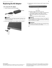
... trademarks of the same type and voltage rating as the original cord or your notebook, then plug it becomes damaged. The AC adapter has no user-replaceable or user-serviceable parts inside. Contact Gateway about returning defective AC adapters. Technical Support See the label on and off. • Make sure the power cord is firmly attached to your reference guide for Customer Care Information...
... trademarks of the same type and voltage rating as the original cord or your notebook, then plug it becomes damaged. The AC adapter has no user-replaceable or user-serviceable parts inside. Contact Gateway about returning defective AC adapters. Technical Support See the label on and off. • Make sure the power cord is firmly attached to your reference guide for Customer Care Information...
8512564 - Component Replacement Manual R0
Page 2
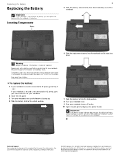
... notebook is incorrectly replaced. Important If the battery charge indicator does not turn off your notebook. 2 Close the LCD panel. 3 Turn your notebook into place. To replace the battery: 1 If your notebook is on and is facing up. 4 Slide the battery lock to the unlock position. 7 Slide the battery lock to the lock position. 8 Turn your notebook over. 9 Plug your notebook over so the bottom is connected to AC power, go to AC power, save your work...
... notebook is incorrectly replaced. Important If the battery charge indicator does not turn off your notebook. 2 Close the LCD panel. 3 Turn your notebook into place. To replace the battery: 1 If your notebook is on and is facing up. 4 Slide the battery lock to the unlock position. 7 Slide the battery lock to the lock position. 8 Turn your notebook over. 9 Plug your notebook over so the bottom is connected to AC power, go to AC power, save your work...
8512564 - Component Replacement Manual R0
Page 3
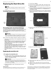
... replacing a component. Do not lay components on your Reference Guide. For more information, see "Changing Batteries" in your workbench or other grounded object. All rights reserved. in a safe place. All other countries. Warning To avoid exposure to dangerous electrical voltages and moving parts, turn off your notebook. 4 Close the LCD panel. 5 Disconnect the AC adapter, modem cable, and network cable. 6 Disconnect all peripheral devices and remove...
... replacing a component. Do not lay components on your Reference Guide. For more information, see "Changing Batteries" in your workbench or other grounded object. All rights reserved. in a safe place. All other countries. Warning To avoid exposure to dangerous electrical voltages and moving parts, turn off your notebook. 4 Close the LCD panel. 5 Disconnect the AC adapter, modem cable, and network cable. 6 Disconnect all peripheral devices and remove...
8512564 - Component Replacement Manual R0
Page 4
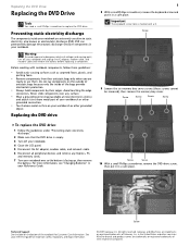
... Replace the memory bay cover, then tighten the six cover screws. 15 Replace the keyboard screw. 16 Insert the battery, then turn your notebook over. 17 Connect the power adapter, modem cable, and network cable, then turn on the DVD bracket. 2 12 Slide the new DVD drive into the drive bay. DVD bracket Technical Support See the label on the bottom of the drive bay by pushing on your reference guide for Customer Care Information. Gateway...
... Replace the memory bay cover, then tighten the six cover screws. 15 Replace the keyboard screw. 16 Insert the battery, then turn your notebook over. 17 Connect the power adapter, modem cable, and network cable, then turn on the DVD bracket. 2 12 Slide the new DVD drive into the drive bay. DVD bracket Technical Support See the label on the bottom of the drive bay by pushing on your reference guide for Customer Care Information. Gateway...
8512564 - Component Replacement Manual R0
Page 5
... parts, turn off your notebook. 4 Disconnect the AC adapter, modem cable, and network cable. 5 Disconnect all peripheral devices and remove any surface. • Wear a grounding wrist strap (available at the Web address or telephone number shown on the label on your notebook. Technical Support See the label on the bottom of your reference guide for software and device driver recovery" in your notebook and unplug the AC adapter, modem cable...
... parts, turn off your notebook. 4 Disconnect the AC adapter, modem cable, and network cable. 5 Disconnect all peripheral devices and remove any surface. • Wear a grounding wrist strap (available at the Web address or telephone number shown on the label on your notebook. Technical Support See the label on the bottom of your reference guide for software and device driver recovery" in your notebook and unplug the AC adapter, modem cable...
8512564 - Component Replacement Manual R0
Page 6
... to you from Gateway with the operating system, applications, and drivers installed, you will see a blank screen, insert the Windows DVD into your notebook's DVD drive, then restart your Drivers and Applications Recovery disc. 18 Reconnect all peripheral devices and replace any Express, PC, and memory cards. As part of their respective companies. Gateway and eMachines are trademarks or registered trademarks of the process, you see the Windows startup screen. All rights...
... to you from Gateway with the operating system, applications, and drivers installed, you will see a blank screen, insert the Windows DVD into your notebook's DVD drive, then restart your Drivers and Applications Recovery disc. 18 Reconnect all peripheral devices and replace any Express, PC, and memory cards. As part of their respective companies. Gateway and eMachines are trademarks or registered trademarks of the process, you see the Windows startup screen. All rights...
8512564 - Component Replacement Manual R0
Page 7
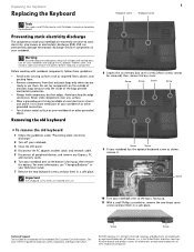
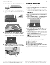
... optional keyboard screw as electrostatic discharge (ESD). in a safe place. Replacing the Keyboard Replacing the Keyboard Tools You need a small Phillips and a small flat-blade screwdriver to a bare metal part of their respective companies. Avoid touching the edge connectors. For more information, see "Changing Batteries" in your Reference Guide. 7 Remove the two keyboard screws and put them . Before working with a K. 1 Keyboard screw Keyboard screw 8 Loosen the six memory bay cover...
... optional keyboard screw as electrostatic discharge (ESD). in a safe place. Replacing the Keyboard Replacing the Keyboard Tools You need a small Phillips and a small flat-blade screwdriver to a bare metal part of their respective companies. Avoid touching the edge connectors. For more information, see "Changing Batteries" in your Reference Guide. 7 Remove the two keyboard screws and put them . Before working with a K. 1 Keyboard screw Keyboard screw 8 Loosen the six memory bay cover...
8512564 - Component Replacement Manual R0
Page 8
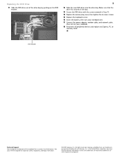
... LCD panel, then replace the two hinge cover screws. 8 Turn your notebook over . 13 Connect the power adapter, the modem cable, and the network cable, then turn on your reference guide for Customer Care Information. Important The keyboard cable is correctly oriented if it clicks in place. All other countries. Be careful to not damage the LCD panel. 18 Slide the black keyboard connector clip to not damage the LCD panel. 6 Replace the keyboard cover...
... LCD panel, then replace the two hinge cover screws. 8 Turn your notebook over . 13 Connect the power adapter, the modem cable, and the network cable, then turn on your reference guide for Customer Care Information. Important The keyboard cable is correctly oriented if it clicks in place. All other countries. Be careful to not damage the LCD panel. 18 Slide the black keyboard connector clip to not damage the LCD panel. 6 Replace the keyboard cover...
8512564 - Component Replacement Manual R0
Page 9
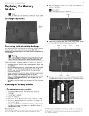
... and moving parts, turn off your notebook. 3 Close the LCD panel. 4 Disconnect the AC adapter, modem cable, and network cable. 5 Disconnect all peripheral devices and remove any Express, PC, and memory cards. 6 Turn your reference guide for Customer Care Information. All other grounded object. Replacing the memory module 8 Loosen the six memory bay cover screws (these guidelines: • Avoid static-causing surfaces such as electrostatic discharge (ESD). Important The keyboard screw...
... and moving parts, turn off your notebook. 3 Close the LCD panel. 4 Disconnect the AC adapter, modem cable, and network cable. 5 Disconnect all peripheral devices and remove any Express, PC, and memory cards. 6 Turn your reference guide for Customer Care Information. All other grounded object. Replacing the memory module 8 Loosen the six memory bay cover screws (these guidelines: • Avoid static-causing surfaces such as electrostatic discharge (ESD). Important The keyboard screw...
8512564 - Component Replacement Manual R0
Page 10
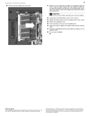
... be inserted in the memory bay. Important Use only memory modules designed for your Gateway notebook. 12 Gently push the module down until it into the empty memory slot. All rights reserved. See your notebook over. 16 Connect the power adapter, the modem cable, and the network cable. 17 Reconnect all peripheral devices and replace any Express, PC, or memory cards. 18 Turn on the bottom of Gateway, Inc. Gateway and eMachines are...
... be inserted in the memory bay. Important Use only memory modules designed for your Gateway notebook. 12 Gently push the module down until it into the empty memory slot. All rights reserved. See your notebook over. 16 Connect the power adapter, the modem cable, and the network cable. 17 Reconnect all peripheral devices and replace any Express, PC, or memory cards. 18 Turn on the bottom of Gateway, Inc. Gateway and eMachines are...
8512564 - Component Replacement Manual R0
Page 11
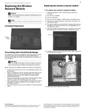
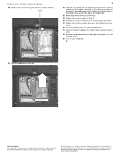
... antenna cables out of Gateway, Inc. Gateway and eMachines are ready to replace the wireless network module. Note which color cable is facing up, then remove the battery. Never slide components over so the bottom is connected to dangerous electrical voltages and moving parts, turn off your notebook. 3 Close the LCD panel. 4 Disconnect the AC adapter, modem cable, and network cable. 5 Disconnect all peripheral devices and remove any Express, PC, and memory cards. 6 Turn your notebook...
... antenna cables out of Gateway, Inc. Gateway and eMachines are ready to replace the wireless network module. Note which color cable is facing up, then remove the battery. Never slide components over so the bottom is connected to dangerous electrical voltages and moving parts, turn off your notebook. 3 Close the LCD panel. 4 Disconnect the AC adapter, modem cable, and network cable. 5 Disconnect all peripheral devices and remove any Express, PC, and memory cards. 6 Turn your notebook...
8512564 - Component Replacement Manual R0
Page 12
... Replace the screw removed in Step 10. 15 Reattach the antenna cables to the corresponding connectors. 16 Replace the wireless network bay cover, then tighten the cover screw. 17 Insert the battery, then turn your reference guide for Customer Care Information. See your notebook over. 18 Connect the power adapter, the modem cable, and the network cable. 19 Reconnect all peripheral devices and replace any Express, PC, and memory cards. 20 Turn on...
... Replace the screw removed in Step 10. 15 Reattach the antenna cables to the corresponding connectors. 16 Replace the wireless network bay cover, then tighten the cover screw. 17 Insert the battery, then turn your reference guide for Customer Care Information. See your notebook over. 18 Connect the power adapter, the modem cable, and the network cable. 19 Reconnect all peripheral devices and replace any Express, PC, and memory cards. 20 Turn on...


