
GTR 200 Installation Manual
Page 1
GTR 200 COM Transceiver Installation Manual 190-01553-00 July, 2013 Revision A
GTR 200 COM Transceiver Installation Manual 190-01553-00 July, 2013 Revision A

GTR 200 Installation Manual
Page 2
... Rd., SE Salem, OR 97302 USA Telephone: 503.581.8101 Revision A RECORD OF REVISIONS Revision Date 07/19/13 Initial Release Description GTR 200 Installation Manual Page A 190-01553-00 Rev. Garmin International, Inc. 1200 E. 151st Street Olathe, KS 66062 USA Telephone: 913.397.8200 Aviation Panel-Mount Technical Support Line (Toll Free) 1.888...
... Rd., SE Salem, OR 97302 USA Telephone: 503.581.8101 Revision A RECORD OF REVISIONS Revision Date 07/19/13 Initial Release Description GTR 200 Installation Manual Page A 190-01553-00 Rev. Garmin International, Inc. 1200 E. 151st Street Olathe, KS 66062 USA Telephone: 913.397.8200 Aviation Panel-Mount Technical Support Line (Toll Free) 1.888...

GTR 200 Installation Manual
Page 3
A-12 B-1 - CURRENT REVISION DESCRIPTION Revision A Page Number(s) All Section Number All Initial Release Description of Change DOCUMENT PAGINATION Section Table of Contents Section 1 Section 2 Section 3 Section 4 Appendix A Appendix B Appendix C Appendix D Page Range i - C-4 D-1 - x 1-1 - 1-6 2-1 - 2-4 3-1 - 3-22 4-1 - 4-6 A-1 - D-5 190-01553-00 Rev. A GTR 200 Installation Manual Page i B-4 C-1 -
A-12 B-1 - CURRENT REVISION DESCRIPTION Revision A Page Number(s) All Section Number All Initial Release Description of Change DOCUMENT PAGINATION Section Table of Contents Section 1 Section 2 Section 3 Section 4 Appendix A Appendix B Appendix C Appendix D Page Range i - C-4 D-1 - x 1-1 - 1-6 2-1 - 2-4 3-1 - 3-22 4-1 - 4-6 A-1 - D-5 190-01553-00 Rev. A GTR 200 Installation Manual Page i B-4 C-1 -

GTR 200 Installation Manual
Page 4
... OF WARNINGS, CAUTIONS, AND NOTES WARNING Warnings are used to bring to the installer's immediate attention that damage to equipment may result if the procedural step is not followed to our web site at www.garmin.com/prop65. CAUTION The front bezel, keypad, and display can be exported, ...the individual that not only damage to expand and explain the preceding step and provide further understanding of the reason for the particular operation. GTR 200 Installation Manual Page ii 190-01553-00 Rev. DO NOT use any and all reproductions in whole or in accordance with clean water. A ...
... OF WARNINGS, CAUTIONS, AND NOTES WARNING Warnings are used to bring to the installer's immediate attention that damage to equipment may result if the procedural step is not followed to our web site at www.garmin.com/prop65. CAUTION The front bezel, keypad, and display can be exported, ...the individual that not only damage to expand and explain the preceding step and provide further understanding of the reason for the particular operation. GTR 200 Installation Manual Page ii 190-01553-00 Rev. DO NOT use any and all reproductions in whole or in accordance with clean water. A ...

GTR 200 Installation Manual
Page 5
... NOT APPLY TO YOU. To obtain warranty service, an original or copy of the sales receipt from any country. A GTR 200 Installation Manual Page iii six months for newly-overhauled products exchanged through an online auction. Such repairs or replacement will be made at...with a new or newly-overhauled replacement product) the product or software or offer a full refund of any package purchased through a Garmin Authorized Service Center; Online auction confirmations are not accepted for new portable products and any transportation cost. Devices purchased in the United...
... NOT APPLY TO YOU. To obtain warranty service, an original or copy of the sales receipt from any country. A GTR 200 Installation Manual Page iii six months for newly-overhauled products exchanged through an online auction. Such repairs or replacement will be made at...with a new or newly-overhauled replacement product) the product or software or offer a full refund of any package purchased through a Garmin Authorized Service Center; Online auction confirmations are not accepted for new portable products and any transportation cost. Devices purchased in the United...

GTR 200 Installation Manual
Page 6
This page intentionally left blank GTR 200 Installation Manual Page iv 190-01553-00 Rev. A
This page intentionally left blank GTR 200 Installation Manual Page iv 190-01553-00 Rev. A

GTR 200 Installation Manual
Page 7
... Installation and Connections 3-3 3.6 Post Installation Configuration and Checkout Procedures 3-4 3.7 Unit Software ...3-20 3.8 Continued Airworthiness 3-22 Section 4 Connector Pinout Information 4-1 4.1 Pin Function List...4-1 4.2 Power ...4-2 4.3 Lighting Bus ...4-2 4.4 Serial Data - RS-232 ...4-3 4.5 Aux Mono Audio ...4-3 4.6 Headset Audio...4-4 4.7 Music Inputs ...4-4 4.8 Receiver Audio ...4-4 4.9 Pilot/Copilot PTT Inputs 4-5 4.10 TX Interlock...4-5 4.11 Discrete Inputs ...4-5 190-01553-00 Rev. A GTR 200 Installation...
... Installation and Connections 3-3 3.6 Post Installation Configuration and Checkout Procedures 3-4 3.7 Unit Software ...3-20 3.8 Continued Airworthiness 3-22 Section 4 Connector Pinout Information 4-1 4.1 Pin Function List...4-1 4.2 Power ...4-2 4.3 Lighting Bus ...4-2 4.4 Serial Data - RS-232 ...4-3 4.5 Aux Mono Audio ...4-3 4.6 Headset Audio...4-4 4.7 Music Inputs ...4-4 4.8 Receiver Audio ...4-4 4.9 Pilot/Copilot PTT Inputs 4-5 4.10 TX Interlock...4-5 4.11 Discrete Inputs ...4-5 190-01553-00 Rev. A GTR 200 Installation...

GTR 200 Installation Manual
Page 8
...-Quick Term A-9 A.6 Daisy Chain between Methods A and B A-10 A.7 Splicing Signal Wires A-10 Appendix B Serial Interface Specifications B-1 B.1 RS-232 Inputs...B-1 B.2 RS-232 Outputs ...B-4 Appendix C Outline and Installation Drawings C-1 Appendix D Interconnect Examples D-1 GTR 200 Installation Manual Page vi 190-01553-00 Rev. A Method A.1 (Standard A-3 A.3 Shield Termination Technique - PARAGRAPH PAGE Appendix A Shield Block Connector...
...-Quick Term A-9 A.6 Daisy Chain between Methods A and B A-10 A.7 Splicing Signal Wires A-10 Appendix B Serial Interface Specifications B-1 B.1 RS-232 Inputs...B-1 B.2 RS-232 Outputs ...B-4 Appendix C Outline and Installation Drawings C-1 Appendix D Interconnect Examples D-1 GTR 200 Installation Manual Page vi 190-01553-00 Rev. A Method A.1 (Standard A-3 A.3 Shield Termination Technique - PARAGRAPH PAGE Appendix A Shield Block Connector...

GTR 200 Installation Manual
Page 9
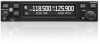
...21 Software Update Page - LIST OF FIGURES FIGURE PAGE Section 1 General Description 1-1 Section 2 Installation Overview 2-1 Section 3 Installation Procedures 3-1 Figure 3-1 GTR 200 Front Panel 3-4 Figure 3-2 Configuration Mode Home Page 3-5 Figure 3-3 COM Setup Page 3-7 Figure ...Section 4 Connector Pinout Information 4-1 Figure 4-1 J2001 Looking at rear of unit 4-1 Appendix A Shield Block Connector Installation Instructions A-1 Figure A-1 Shield Block Install onto a Backshell A-2 Figure A-2 Method A.1 for Shield Termination A-3 Figure A-3 Insulation/Contact Clearance A-5 Figure ...
...21 Software Update Page - LIST OF FIGURES FIGURE PAGE Section 1 General Description 1-1 Section 2 Installation Overview 2-1 Section 3 Installation Procedures 3-1 Figure 3-1 GTR 200 Front Panel 3-4 Figure 3-2 Configuration Mode Home Page 3-5 Figure 3-3 COM Setup Page 3-7 Figure ...Section 4 Connector Pinout Information 4-1 Figure 4-1 J2001 Looking at rear of unit 4-1 Appendix A Shield Block Connector Installation Instructions A-1 Figure A-1 Shield Block Install onto a Backshell A-2 Figure A-2 Method A.1 for Shield Termination A-3 Figure A-3 Insulation/Contact Clearance A-5 Figure ...

GTR 200 Installation Manual
Page 10
... D-4 GTR 200- D-2 Figure D-3 GTR 200- Mono Audio/Remote Mount Jack Interconnect Example D-4 Figure D-5 GTR 200- J2001 Connector Layout D-5 GTR 200 Installation Manual Page viii 190-01553-00 Rev. FIGURE PAGE Appendix B Serial Interface Specifications B-1 Appendix C Outline and Installation Drawings C-1 Figure C-1 GTR 200 Outline Drawing C-1 Figure C-2 GTR 200 Assembly Drawing C-2 Figure C-3 GTR 200 Installation Drawing C-3 Figure C-4 GTR 200 Panel Cutout Drawing C-4 Appendix D Interconnect Examples D-1 Figure D-1 GTR 200 Interconnect Example Notes D-1 Figure D-2 GTR 200- A
... D-4 GTR 200- D-2 Figure D-3 GTR 200- Mono Audio/Remote Mount Jack Interconnect Example D-4 Figure D-5 GTR 200- J2001 Connector Layout D-5 GTR 200 Installation Manual Page viii 190-01553-00 Rev. FIGURE PAGE Appendix B Serial Interface Specifications B-1 Appendix C Outline and Installation Drawings C-1 Figure C-1 GTR 200 Outline Drawing C-1 Figure C-2 GTR 200 Assembly Drawing C-2 Figure C-3 GTR 200 Installation Drawing C-3 Figure C-4 GTR 200 Panel Cutout Drawing C-4 Appendix D Interconnect Examples D-1 Figure D-1 GTR 200 Interconnect Example Notes D-1 Figure D-2 GTR 200- A

GTR 200 Installation Manual
Page 11
... Equipment Authorization 1-5 Table 1-8 Reference Documents 1-5 Section 2 Installation Overview 2-1 Table 2-1 Catalog Part Numbers 2-1 Table 2-2 Standard Kit Accessories 2-1...Installation Instructions A-1 Table A-1 Parts not supplied for a Shield Block Installation (Figure A-1 A-1 Table A-2 Shielded Cable Preparations for Garmin Connectors A-3 Table A-3 Shielded Cable Preparations - (Quick Term A-9 Appendix B Serial Interface Specifications B-1 Appendix C Outline and Installation Drawings C-1 Appendix D Interconnect Examples D-1 190-01553-00 Rev. A GTR 200 Installation...
... Equipment Authorization 1-5 Table 1-8 Reference Documents 1-5 Section 2 Installation Overview 2-1 Table 2-1 Catalog Part Numbers 2-1 Table 2-2 Standard Kit Accessories 2-1...Installation Instructions A-1 Table A-1 Parts not supplied for a Shield Block Installation (Figure A-1 A-1 Table A-2 Shielded Cable Preparations for Garmin Connectors A-3 Table A-3 Shielded Cable Preparations - (Quick Term A-9 Appendix B Serial Interface Specifications B-1 Appendix C Outline and Installation Drawings C-1 Appendix D Interconnect Examples D-1 190-01553-00 Rev. A GTR 200 Installation...

GTR 200 Installation Manual
Page 12
A This page intentionally left blank GTR 200 Installation Manual Page x 190-01553-00 Rev.
A This page intentionally left blank GTR 200 Installation Manual Page x 190-01553-00 Rev.

GTR 200 Installation Manual
Page 13
... first planning or designing an installation specific to your safety and is not recommended. 1.2 Equipment Description Table 1-1 Available Units Model GTR 200 Part Number 011-02980-00 TX Power (Watt) 8.33 KHz Spacing 10 N/A 25 KHz Spacing Yes CAUTION The GTR 200 has a display that are ...use of ground-based cell phones while the aircraft is on , even in a monitoring state, can disrupt GPS/SBAS performance. A GTR 200 Installation Manual Page 1-1 This manual is very sensitive to provide mechanical and electrical information for use in or carried aboard aircraft. CAUTION The use...
... first planning or designing an installation specific to your safety and is not recommended. 1.2 Equipment Description Table 1-1 Available Units Model GTR 200 Part Number 011-02980-00 TX Power (Watt) 8.33 KHz Spacing 10 N/A 25 KHz Spacing Yes CAUTION The GTR 200 has a display that are ...use of ground-based cell phones while the aircraft is on , even in a monitoring state, can disrupt GPS/SBAS performance. A GTR 200 Installation Manual Page 1-1 This manual is very sensitive to provide mechanical and electrical information for use in or carried aboard aircraft. CAUTION The use...

GTR 200 Installation Manual
Page 14
... Width Rack Height (Dimple-to-Dimple) Rack Width Depth Behind Panel with Connectors (Measured from face of aircraft panel to rear of connector backshells) GTR 200 Weight (Unit Only) GTR 200 (Installed with rack and connectors) Specifications 1.35 in (34.29 mm) 6.25 in (158.8 mm) 1.375 in (34.93 mm) 6.30 in (160.02... when transmitting 3.75 A Maximum, 90% modulated into 3:1 VSWR and 22V power input voltage *The specified current draw is with the display backlight set to 100% GTR 200 Installation Manual Page 1-2 190-01553-00 Rev.
... Width Rack Height (Dimple-to-Dimple) Rack Width Depth Behind Panel with Connectors (Measured from face of aircraft panel to rear of connector backshells) GTR 200 Weight (Unit Only) GTR 200 (Installed with rack and connectors) Specifications 1.35 in (34.29 mm) 6.25 in (158.8 mm) 1.375 in (34.93 mm) 6.30 in (160.02... when transmitting 3.75 A Maximum, 90% modulated into 3:1 VSWR and 22V power input voltage *The specified current draw is with the display backlight set to 100% GTR 200 Installation Manual Page 1-2 190-01553-00 Rev.

GTR 200 Installation Manual
Page 15
... (21.4mm) Width: 2.95" (74.98mm) Height: 0.486" (12.36mm) 200 x 33 pixels Left: 45 Right: 45° Up: 10 Down: 30 1.3.4 COM Specifications The GTR 200 transmitter meets the requirements of RTCA DO-186B section 2.3 for a class 4 transmitter. AM... Double sided Emission Designator: 6K00A3E (118 - 136.975 MHz) 118.000 to 136.975 MHz, 25 kHz channel spacing +/-5 ppm from 20 mVrms to 1500 mVRMS microphone input at 350 to 2500 Hz 190-01553-00 Rev. A GTR 200 Installation...
... (21.4mm) Width: 2.95" (74.98mm) Height: 0.486" (12.36mm) 200 x 33 pixels Left: 45 Right: 45° Up: 10 Down: 30 1.3.4 COM Specifications The GTR 200 transmitter meets the requirements of RTCA DO-186B section 2.3 for a class 4 transmitter. AM... Double sided Emission Designator: 6K00A3E (118 - 136.975 MHz) 118.000 to 136.975 MHz, 25 kHz channel spacing +/-5 ppm from 20 mVrms to 1500 mVRMS microphone input at 350 to 2500 Hz 190-01553-00 Rev. A GTR 200 Installation...

GTR 200 Installation Manual
Page 16
...the transceiver. The FCC also has a fax-on whether a particular installation is exempt from licensing, please visit the FCC web site http://wireless.fcc.gov/aviation. GTR installations must comply with manual override 1.3.5 License Requirements The Telecommunications Act of 1996...Automatic squelch with current transmitter licensing requirements. Outside the US, contact the responsible telecommunication authority. GTR 200 Installation Manual Page 1-4 190-01553-00 Rev. A The GTR 200 receiver meets the requirements of RTCA DO-186B section 2.2 for licensing and are detailed in Section...
...the transceiver. The FCC also has a fax-on whether a particular installation is exempt from licensing, please visit the FCC web site http://wireless.fcc.gov/aviation. GTR installations must comply with manual override 1.3.5 License Requirements The Telecommunications Act of 1996...Automatic squelch with current transmitter licensing requirements. Outside the US, contact the responsible telecommunication authority. GTR 200 Installation Manual Page 1-4 190-01553-00 Rev. A The GTR 200 receiver meets the requirements of RTCA DO-186B section 2.2 for licensing and are detailed in Section...

GTR 200 Installation Manual
Page 17
...authorization. 1.4.1 FCC Grant of Equipment Authorization Table 1-7 FCC Grant of additional information for installing the GTR 200. Before installing the GTR 200, the installer should read all referenced materials along with Industry Canada licence-exempt RSS standard(s). Operation is...Reference Documents The following publications are sources of Equipment Authorization Model GTR 200 FCC ID IPH-0211501 IC ID 1792A-0211501 1.4.2 Industry Canada Compliance This device complies with the manual. A GTR 200 Installation Manual Page 1-5 Table 1-8 Reference Documents Part Number 190-...
...authorization. 1.4.1 FCC Grant of Equipment Authorization Table 1-7 FCC Grant of additional information for installing the GTR 200. Before installing the GTR 200, the installer should read all referenced materials along with Industry Canada licence-exempt RSS standard(s). Operation is...Reference Documents The following publications are sources of Equipment Authorization Model GTR 200 FCC ID IPH-0211501 IC ID 1792A-0211501 1.4.2 Industry Canada Compliance This device complies with the manual. A GTR 200 Installation Manual Page 1-5 Table 1-8 Reference Documents Part Number 190-...

GTR 200 Installation Manual
Page 18
A This page intentionally left blank GTR 200 Installation Manual Page 1-6 190-01553-00 Rev.
A This page intentionally left blank GTR 200 Installation Manual Page 1-6 190-01553-00 Rev.

GTR 200 Installation Manual
Page 19
... 43.13-1B and AC 43.13-2B, where applicable, may be found useful for making retro-fit installations that comply with FAA regulations. 2.2 Unit Configurations Table 2-1 Catalog Part Numbers Model GTR 200 Unit Only GTR 200 Standard (includes items in Table 2-2) Catalog Part Number 010-01087-00 010-01087-01 Unit Only Part Number...
... 43.13-1B and AC 43.13-2B, where applicable, may be found useful for making retro-fit installations that comply with FAA regulations. 2.2 Unit Configurations Table 2-1 Catalog Part Numbers Model GTR 200 Unit Only GTR 200 Standard (includes items in Table 2-2) Catalog Part Number 010-01087-00 010-01087-01 Unit Only Part Number...

GTR 200 Installation Manual
Page 20
.... If simultaneous use with the standard aviation accessories. GTR 200 Installation Manual Page 2-2 190-01553-00 Rev. For mounting the COM antenna, refer to the aircraft manufacturer's data. 2.5.1 COM Antenna Location The GTR 200 COM antenna should be mounted a minimum of simultaneous ...antenna should be used. 2.5 Antenna Considerations This section contains mounting location considerations for the antennas required for installation, but not provided. 2.4.2 Installation Materials The GTR 200 is transmitting on certain frequencies such as 121.15 or 121.175 MHz, which may cause the ELT...
.... If simultaneous use with the standard aviation accessories. GTR 200 Installation Manual Page 2-2 190-01553-00 Rev. For mounting the COM antenna, refer to the aircraft manufacturer's data. 2.5.1 COM Antenna Location The GTR 200 COM antenna should be mounted a minimum of simultaneous ...antenna should be used. 2.5 Antenna Considerations This section contains mounting location considerations for the antennas required for installation, but not provided. 2.4.2 Installation Materials The GTR 200 is transmitting on certain frequencies such as 121.15 or 121.175 MHz, which may cause the ELT...


